Sachpazis: Masonry wall panel design example (EN1996 1-1-2005)
•
1 gostou•1,594 visualizações

This document summarizes the design of an unreinforced masonry wall panel according to EN1996-1-1:2005. It provides details of the wall geometry, material properties, loads, and design calculations for strength and serviceability limit states. The calculations show the wall satisfies the strength and serviceability requirements for vertical loading and lateral wind loading according to the code.

Recomendados
Recomendados
Mais conteúdo relacionado
Mais procurados
Mais procurados (20)
Destaque
Destaque (14)
Semelhante a Sachpazis: Masonry wall panel design example (EN1996 1-1-2005)
Semelhante a Sachpazis: Masonry wall panel design example (EN1996 1-1-2005) (20)
Mais de Dr.Costas Sachpazis
Mais de Dr.Costas Sachpazis (20)
Último
Último (20)
Sachpazis: Masonry wall panel design example (EN1996 1-1-2005)
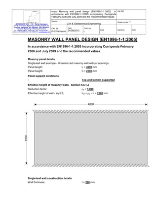
- 1. Project: Masonry wall panel design (EN1996-1-1:2005) in accordance with EN1996-1-1:2005 incorporating Corrigenda February 2006 and July 2009 and the Recommended Values Job Ref. Section Sheet no./rev. 1 Civil & Geotechnical Engineering GEODOMISI Ltd. - Dr. Costas Sachpazis Civil & Geotechnical Engineering Consulting Company for Structural Engineering, Soil Mechanics, Rock Mechanics, Foundation Engineering & Retaining Structures. Tel.: (+30) 210 5238127, 210 5711263 - Fax.:+30 210 5711461 Mobile: (+30) 6936425722 & (+44) 7585939944, costas@sachpazis.info Calc. by Date Dr.C.Sachpazis 04/08/2013 Chk'd by - Date App'd by Date MASONRY WALL PANEL DESIGN (EN1996-1-1:2005) In accordance with EN1996-1-1:2005 incorporating Corrigenda February 2006 and July 2009 and the recommended values Masonry panel details Single-leaf wall example - Unreinforced masonry wall without openings Panel length; L = 4800 mm Panel height; h = 2200 mm Panel support conditions ; Top and bottom supported Effective height of masonry walls - Section 5.5.1.2 Reduction factor; ρ2 = 1.000 Effective height of wall - eq 5.2; hef = ρ2 × h = 2200 mm Single-leaf wall construction details Wall thickness; t = 200 mm
- 2. Project: Masonry wall panel design (EN1996-1-1:2005) in accordance with EN1996-1-1:2005 incorporating Corrigenda February 2006 and July 2009 and the Recommended Values Job Ref. Section Sheet no./rev. 1 Civil & Geotechnical Engineering GEODOMISI Ltd. - Dr. Costas Sachpazis Civil & Geotechnical Engineering Consulting Company for Structural Engineering, Soil Mechanics, Rock Mechanics, Foundation Engineering & Retaining Structures. Tel.: (+30) 210 5238127, 210 5711263 - Fax.:+30 210 5711461 Mobile: (+30) 6936425722 & (+44) 7585939944, costas@sachpazis.info Calc. by Date Dr.C.Sachpazis 04/08/2013 Chk'd by Date - App'd by Date Effective thickness of masonry walls - Section 5.5.1.3 Effective thickness; tef = t = 200 mm Masonry details Masonry type; Clay - Group 1 Mean compressive strength of masonry unit; fb = 20 N/mm Density of masonry; γ = 20 kN/m 2 3 Mortar type; M4 - General purpose mortar Compressive strength of masonry mortar; fm = 4 N/mm Compressive strength factor - Table 3.3; K = 0.55 2 Characteristic compressive strength of masonry - eq 3.2 fk = K × fb 0.7 × fm 0.3 = 6.787 N/mm 2 Characteristic flexural strength of masonry having a plane of failure parallel to the bed joints - cl 3.6.3 fxk1 = 0.1 N/mm 2 Characteristic flexural strength of masonry having a plane of failure perpendicular to the bed joints - cl 3.6.3 fxk2 = 0.2 N/mm 2 Lateral loading details Characteristic wind load on panel; W k = 1.120 kN/m 2 Vertical loading details Permanent load on top of wall; Gk = 22.5 kN/m; Variable load on top of wall; Qk = 12.5 kN/m; at an eccentricity of 20 mm
- 3. Project: Masonry wall panel design (EN1996-1-1:2005) in accordance with EN1996-1-1:2005 incorporating Corrigenda February 2006 and July 2009 and the Recommended Values Job Ref. Section Sheet no./rev. 1 Civil & Geotechnical Engineering GEODOMISI Ltd. - Dr. Costas Sachpazis Civil & Geotechnical Engineering Consulting Company for Structural Engineering, Soil Mechanics, Rock Mechanics, Foundation Engineering & Retaining Structures. Tel.: (+30) 210 5238127, 210 5711263 - Fax.:+30 210 5711461 Mobile: (+30) 6936425722 & (+44) 7585939944, costas@sachpazis.info Calc. by Date Chk'd by Dr.C.Sachpazis 04/08/2013 - Date App'd by Date Partial factors for material strength Category of manufacturing control; Category I Class of execution control; Class 1 Partial factor for masonry in compressive flexure; γMc = 1.70 Partial factor for masonry in tensile flexure; γMt = 1.70 Partial factor for masonry in shear; γMv = 1.70 Slenderness ratio of masonry walls - Section 5.5.1.4 Allowable slenderness ratio; SRall = 27 Slenderness ratio; SR = hef / tef = 11.0 PASS - Slenderness ratio is less than maximum allowable Unreinforced masonry walls subjected to lateral loading - Section 6.3 Limiting height and length to thickness ratio for walls under serviceability limit state - Annex F Length to thickness ratio; L / t = 24 Limiting height to thickness ratio - Annex F; 30 Height to thickness ratio; h / t = 11 PASS - Limiting height to thickness ratio is not exceeded Partial safety factors for design loads Partial safety factor for variable wind load; γfW = 1.50 Partial safety factor for permanent load; γfG = 1.00 Design moments of resistance in panels Self weight at middle of wall; Swt = 0.5 × h × t × γ = 4.4 kN/m Design compressive strength of masonry; fd = fk / γMc = 3.993 N/mm Design vertical compressive stress; σd = min(γfG × (Gk + Swt) / t, 0.2 × fd) = 0.135 N/mm 2 Design flexural strength of masonry parallel to bed joints fxd1 = fxk1 / γMc = 0.059 N/mm 2 Apparent design flexural strength of masonry parallel to bed joints fxd1,app = fxd1 + σd = 0.193 N/mm 2 Design flexural strength of masonry perpendicular to bed joints fxd2 = fxk2 / γMc = 0.118 N/mm Elastic section modulus of wall; 2 2 3 Z = t / 6 = 6666667 mm /m Moment of resistance parallel to bed joints - eq.6.15 MRd1 = fxd1,app × Z = 1.289 kNm/m Moment of resistance perpendicular to bed joints - eq.6.15 MRd2 = fxd2 × Z = 0.784 kNm/m 2
- 4. Project: Masonry wall panel design (EN1996-1-1:2005) in accordance with EN1996-1-1:2005 incorporating Corrigenda February 2006 and July 2009 and the Recommended Values Job Ref. Section Sheet no./rev. 1 Civil & Geotechnical Engineering GEODOMISI Ltd. - Dr. Costas Sachpazis Civil & Geotechnical Engineering Consulting Company for Structural Engineering, Soil Mechanics, Rock Mechanics, Foundation Engineering & Retaining Structures. Tel.: (+30) 210 5238127, 210 5711263 - Fax.:+30 210 5711461 Mobile: (+30) 6936425722 & (+44) 7585939944, costas@sachpazis.info Calc. by Date Chk'd by Dr.C.Sachpazis 04/08/2013 - Date App'd by Date Design moment in panels Using elastic analysis to determine bending moment coefficients for a vertically spanning panel Bending moment coefficient; α = 0.125 Design moment in wall; MEd = γfW × α × W k × h = 1.016 kNm/m 2 PASS - Resistance moment exceeds design moment Unreinforced masonry walls subjected to mainly vertical loading - Section 6.1 Partial safety factors for design loads Partial safety factor for permanent load; γfG = 1.35 Partial safety factor for variable imposed load; γfQ = 1.50 Check vertical loads Reduction factor for slenderness and eccentricity - Section 6.1.2.2 Mid = γfG × Gk × eG + γfQ × Design bending moment at top or bottom of wall; Qk × eQ = 0.4 kNm/m Design vertical load at top or bottom of wall; Nid = γfG × Gk + γfQ × Qk = 49.1 kN/m Initial eccentricity - cl.5.5.1.1; einit = hef / 450 = 4.9 mm Eccentricity due to horizontal load; eh = MEd / Nid = 20.7 mm Eccentricity at top or bottom of wall - eq.6.5; ei = max(Mid / Nid + eh + einit, 0.05 × t) = 33.2 mm Φi = max(1 - 2 × ei / t, 0) Reduction factor at top or bottom of wall - eq.6.4; = 0.668 Design bending moment at middle of wall; Mmd = γfG × Gk × eG + γfQ × Qk × eQ = 0.4 kNm/m Design vertical load at middle of wall; Nmd = γfG × Gk + γfQ × Qk + t × γ × h / 2 = 53.5 kN/m Eccentricity due to horizontal load; ehm = MEd / Nmd = 19 mm em = Mmd / Nmd + ehm + Eccentricity at middle of wall due to loads - eq.6.7; einit = 30.9 mm Eccentricity at middle of wall due to creep; ek = 0 mm Eccentricity at middle of wall - eq.6.6; emk = max(em + ek, 0.05 × t) = 30.9 mm From eq.G.2; A1 = 1 - 2 × emk / t = 0.691 Short term secant modulus of elasticity factor; KE = 1000 2 Modulus of elasticity - cl.3.7.2; E = KE × fk = 6787 N/mm Slenderness - eq.G.4; λ = (hef / tef) × √(fk / E) = 0.348 From eq.G.3; u = (λ - 0.063) / (0.73 - 1.17 × emk / t) = 0.519 Reduction factor at middle of wall - eq.G.1; Φm = max(A1 × ee Reduction factor for slenderness and eccentricity; -(u × u)/2 , 0) = 0.604 Φ = min(Φi, Φm) = 0.604 Verification of unreinforced masonry walls subjected to mainly vertical loading - Section 6.1.2 Design value of the vertical load; NEd = max(Nid, Nmd) = 53.525 kN/m
- 5. Project: Masonry wall panel design (EN1996-1-1:2005) in accordance with EN1996-1-1:2005 incorporating Corrigenda February 2006 and July 2009 and the Recommended Values Job Ref. Section Sheet no./rev. 1 Civil & Geotechnical Engineering GEODOMISI Ltd. - Dr. Costas Sachpazis Civil & Geotechnical Engineering Consulting Company for Structural Engineering, Soil Mechanics, Rock Mechanics, Foundation Engineering & Retaining Structures. Tel.: (+30) 210 5238127, 210 5711263 - Fax.:+30 210 5711461 Mobile: (+30) 6936425722 & (+44) 7585939944, costas@sachpazis.info Date Calc. by Dr.C.Sachpazis 04/08/2013 Chk'd by - Date App'd by Date 2 Design compressive strength of masonry; fd = fk / γMc = 3.993 N/mm Vertical resistance of wall - eq.6.2; NRd = Φ × t × fd = 482.471 kN/m PASS - Design vertical resistance exceeds applied design vertical load