

Recomendados
Mais conteúdo relacionado
Mais procurados
Mais procurados (20)
Semelhante a 1460 1450 plug valve with pneu & elect actuator
Semelhante a 1460 1450 plug valve with pneu & elect actuator (20)
Mais de Chaitannya Mahatme
Mais de Chaitannya Mahatme (20)
1460 1450 plug valve with pneu & elect actuator
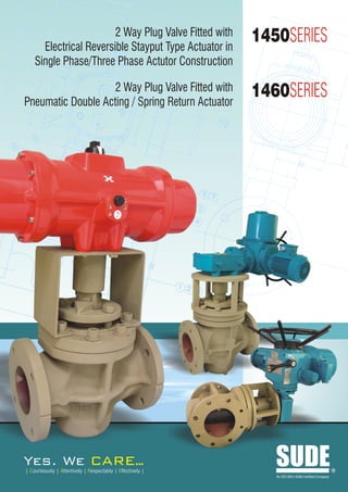
- 1. 2 Way Plug Valve Fitted with Electrical Reversible Stayput Type Actuator in 1450SERIES Single Phase/Three Phase Actutor Construction 2 Way Plug Valve Fitted with Pneumatic Double Acting / Spring Return Actuator 1460SERIES Yes. We ARE.. . | Courteously | Attentively | Respectably | Effectively | SUDE An ISO 9001:2008 Certified Company R
- 2. 2 Way Plug Valve Fitted with Electrical Reversible Stayput Type Actuator in Single Phase/Three Phase Actutor Pneumatic Double Acting / Spring Return Actuator Index Introduction Product Introduction ………….…………. 01 Sude is totally committed for providing highest quality valves and outstanding service to our customers. Complete customer satisfaction is Principles and Maintenance …………… 03 our goal. Sealants ………………………………....…. 03 Incorporating the latest in valve technologies Sude assures a consistent, Storage and Handling of Sealants ..... 04 high quality valve that will provide years of trouble-free service Standard Construction ………………..... 05 The plug valve is the oldest of the valves. Plug valves have been in use for over many years. This valve has been in continuous development over Standard & Pattern …………………….... 07 recent years. The plug valve is basically Ski on-off valve based on a plug Flow Characteristics …………………...… 07 with a rectangular hole through which the fluid flows. The plug is either tapered or cylindrical and is located in the valve body and can be rotated Inherent Flow Characteristics …………. 08 through a quarter turn to line the hole up with the pipe when open or across the pipe when closed. Applications ……………………....………. 09 The plug can be adapted for multi-port use allows the valve to be used for 2 Way Plug Valve fitted with Pneumatic Actuator ………………...…... 10 diverting flow. The valve can engineered with a lubricated plug which uses the lubricant to enable convenient operation over a wide range of Specifications ………..…………....…….... 10 pressures. The lubrication film also provides a seal. Tests ..................................................... 11 The un lubricated design includes seals in the plug and requires plastic 2 Way Plug Valve fitted with bearing systems. The valve can include a cage between the plug and the Electrical Actuator …….…………...……...12 body and the remote maintenance e.g. the nuclear industry. Actuator Construction ………....………… 13 Plug Valves- are valves with cylindrical or conically tapered “Plugs” which can be rotated inside the valve body to control flow through the valve. The GA Drawings …………....………………… 15 plugs in plug valves have one or more hollow passageways going sideways through the plug. So that fluid can flow through the plug when the valve opens. Plug valves are simple and often economical. When the plug is conically-tapered, the stem/Actuators are typically attached to the larges diameter end of the plug and without actuator they are exposed to the outside since they do not have the bonnet. The simplest and most common general type of plug valve is a 2-port valve, which has two positions, opens to allow flow and shut (closed) to stop flow. Ports are openings in the valve body through body which includes the bearing sealing systems and allow convenient maintenance. These valves have been specially developed for use in industries. 01 1450/1460SERIES SUDE
- 3. SUDE In quarter turn Plug valve in which you can decide which fluid has to enter or leave, in such valves the plug has one passage way going through it. The ports are typically at opposite ends of the body; therefore the plug is rotated a fourth of a full turn to change from open to shut positions. Slightly conically-tapered metal (often brass) plug valves are often used as simple shut-off valves in household natural gas lines. Flow Positions It is also possible for a plug valve to have more than three ports. In a three way plug valve, flow from one port could be directed to either the second or third port. A 3-way plug valve could also be designed to shift flow between ports 1 and 2, 2 and 3 or 1 and 3 and possibly even connect all three ports together. The flow-directing possibilities in multi-port plug valves are similar to the one in which plug valve will have one port on one side of the plug valve and two ports on the other side, with two diagonal and parallel fluid pathways inside the plug. In this case the plug can be rotated 1800 to connect the port on the one side to either of the two ports on the other side (Refer figure 1) Three Way L-Ported Valves Positions of Three Way T-ported Valves Positions of Four Way Valves Figure 1 Why an Eccentric Plug Valve ? Installed in thousands of applications, the eccentric plug valve has proven itself as the valve of choice in wastewater applications. Unlike a multi-turn gate valve, the eccentric plug valve is a quarter turn valve allowing cost effective, low torque actuation for shut-off and throttling service. And while the gate valve leaves its operating stem exposed to the flow, the plug valve shaft and gear are both removed from the flow and protected from the media. Slurries and sewage are easily handled without clogging and with minimal head loss due to the valves linear flow path. The valve's eccentric action rotates the plug in and out of the seat without scraping or binding. The combination of the eccentric action and heavy duty nickel seat assures long life with minimal maintenance. Increased Port Area For Increased Flow Plug valves are designed to provide low head loss to maximize flow and reduce operating costs. 100% port areas are standard on valves size up to 4 inches and smaller optional on valves 6 inches and larger. Standard port areas for 6 inch and larger valves are larger than traditional rectangular ported valves. SUDE 1450/1460SERIES 02
- 4. Principles and Maintenance SUDE As the valve is operated, a film of sealant is spread Principles of Operation evenly between the seating surfaces and if valves should The Taper Plug Valve, manufactured in sizes from ½" to become difficult to turn, sealant pressure may be built up 12", is used on a wide variety of liquid, gaseous and in the small end chamber underneath the plug, so that the slurry services. plug is eased slightly in its seat and operability is The tapered plug is held firmly into its tapered seat but restored. can be so adjusted that complete leaktightness is The design of the sealant system ensures that any achieved together with smooth valve operation. The sealant groove which is exposed to the line fluid during tapered seating surfaces of the plug and body are not operation is isolated from the sealant supply. Thus loss of exposed to the line fluid when the valve is in the open sealant into the pipeline is avoided, as well as facilitating position, so that the effects of corrosion and erosion are valve operation, the special sealant also perfects the seal confined to the less important parts of the valve. Also between the accurately matched seating surfaces and so since there is a straight flowpath through the valve, there is very little resistance to flow and pressure loss is assures positive leaktightness. minimised. The sealants are specially formulated for use in Plug Valves. It is extremely important that only instructed sealant be used as they retain their properties over a Sealant Type wide temperature range, resist corrosive attack and have many other characteristics necessary for the efficient Plug Valves they are normally filled with sealant, Refer operation of Plug Valves. Similarly, other without factory figure 2, for detail refer Sude since they are applied based on the application instruction sealant should not be used which may damage the plug of the Plug Valve. The frequency of the sealant injection and the quality of Maintenance sealant needed will depend on many factors specific to Key gland nuts the particular duty. The operating regime of the valve, the reasonably tight temperature and pressure of the fluid the age and Inject Instant condition of the valve are all important factors. Most important of all is the composition and nature of the line fluid and especially its effect on the recommended sealant. All of these variables make it difficult to make positive recommendations which would apply to all circumstances, but the following table provides useful tips on the lubrication of Plug valves indicating when the same should apply considering the frequency and the times the lubrication required (Refer table 1 and 2) Fig. 2 Consult Sude for full Overhaul & Repair Manual, available on request, before attempting any maintenance Table 1 operations other than those described here. On average valve should be lubricated Frequency of Valve Operation Not more than Not less than Over 100 times per shift Each shift Weekly Sealant Injection 10 to 100 times per day. Daily Weekly Lubrication of the seating surfaces is by means of a 1 to 10 times daily. Weekly Monthly specially compounded valve sealant which is fed into the 1 to 30 times monthly. Monthly Quarterly operating shank of the valve, either in the form of mastic Less frequently Quarterly Twice Annually sticks or by sealant gun. The sealant then passes through a non-return valve into a system of grooves and ducts on the Note: Valve with Actuator Assembly has direct provision plug and body. for applying sealant without disturbing the assembly. 03 1450/1460SERIES SUDE
- 5. SUDE Multi-purpose Plug Sealants Table 2 Temperature Range* Sealant Form Colour Recommended for Do not use on Min. Max. Sticks -150C 2300C Most chemical plant services, (all sizes) water, aqueous solutions, Strong acid solutions, 731 Cream 0 -20 C 0 230 C Cartridges dilute acids, all alkaline solutions, petroleum products. Bulk -250C 2300C compressed air, tars, bitumens. Most hydrocarbons, butane, propane, Sticks 00C 2500C gasoline, kerosene, oils, fuel oils. (all sizes) Natural gas, manufactured gas Strong alkalies, 733 Cream high aromatic solvents. Cartridges -100C 2500C (including gas with carbon dioxide, Bulk -150C 2500C hydrogen sulphide, water and condensate), LPG, glycols. *Temperature range is dependent upon nature of service. Storage and Handling of Sealants SUDE Sealants should be stored in clean, dry conditions away from heat and flame and strong oxidising agents. Keep containers until required for use. All our sealants have flash points above 1500C but some will burn if subjected to sufficiently fierce flames. If any sealant is incinerated avoid breathing the fumes. Normal hygiene procedures should be followed e.g. avoid prolonged skin contact, wash hands thoroughly after use, etc. Data sheets for each sealant are available on request. SUDE 1450/1460SERIES 04
- 6. Standard Construction SUDE Standard Type Valve The Standard type valve has its integral operating shank at the large end of the taper plug. (Refer Fig. 3) The plug is seated by means of forces applied through the gland 1 packing housed in the cover which also seals the shank against leakage. 3 To prevent damage to the packing where it would 9 otherwise rub on the top of the plug, it bears on a metal shim which is clamped between the body and the cover. 4 This reduces friction between the plug and the packing and also acts as a separate and very effective seal against leakage of the line fluid into the packing space. 5 6 17 1 1 18 9 2 11 10 3 11 4 12 12 5 6 13 13 7 14 15 8 8 16 Parts 1 Sealant Injector 10 Stop 2 Indicator 11 Cover 14 3 Gland Nuts 12 Shim 4 Gland 13 Gasket 5 Gland Packing 14 Body 6 Packing Ring 15 Sealant Grooves 7 Sealant Duct 16 Sealant Chamber 8 Plug 17 Gland Studs 9 Check Valve 18 Cover Bolts Fig. 3 Sealant Screw (up to 40mm) 05 1450/1460SERIES SUDE
- 7. SUDE Inverted Type Valve The larger sizes of the Regular Pattern valves are of the INVERTED TYPE (Refer Fig. 4). In this design, the plug tapers towards its upper end and is firmly seated by means of a loading screw passing through the cover 16 which seals the valve base. 17 The sealant chamber is at the upper end of the plug, and 1 the plug seating is independent of the gland, which serves only to seal the plug shank against leakage to 2 atmosphere. These large valves are normally operated by actuators. 3 18 1 2 3 4 8 8 4 5 6 9 5 7 11 10 6 13 12 14 7 9 10 Parts 11 1 Gland 10 Diaphragm 12 2 Gland Packing 11 Pressure Plate 3 Body 12 Cover 13 4 Plug 13 Plug Loading Screw 14 5 Plug Ball Seat 14 Locknut 15 6 Ball 15 Cover Bolts 7 Ball Seat 16 Gland Stud Nuts 8 Sealant Grooves 17 Gland Studs 9 Joint Ring 18 Key Fig. 4 SUDE 1450/1460SERIES 06
- 8. Standard & Pattern SUDE Cast iron plug valves with threaded ends or with flanges, for general purposes, are covered in BS5158. Flanges conform to BS4504 or ANSI B16.1 The plug valves are available in Regular, Short Pattern. The different patterns vary as regards end-to-end dimensions and port area for a given size of valve and conform to BS5158 definitions. Regular pattern valves have end-to-end dimensions in accordance with BS5158 Long and ANSI B16.10. The plug ports of these valves are rectangular in shape but are substantially full area giving the minimum flow restriction for a given size of valve. Short pattern valves have end-to-end dimensions in accordance with BS5158 Short and ANSI B16.10. which make them interchangeable with Class 125. As a consequence of this short end-to-end dimension, port area is reduced compared with regular pattern valves and the change in shape from circular pipe bore to rectangular plug port is more abrupt. Flow Characteristics SUDE Cubic Meters per Hour 10,000 20,000 30,000 1,000 2,000 3,000 4,000 5,000 6,000 7,000 8,000 100 200 300 400 500 600 700 800 10 20 30 40 50 60 70 80 8 7 6 5 4 3 2 Head Loss (Feet of Water) 1 Meters of Water .8 .7 .6 .5 .4 .3 .2 .1 .08 .07 .06 .05 .04 .03 Flow of Water (Gallons per minute) 07 1450/1460SERIES SUDE
- 9. Inherent Flow Characteristics SUDE 100 90 80 BUTTERFLY VALVE 70 60 Percent of Full Open CV PLUG VALVE 50 40 BALL VALVE 30 20 10 0 0 10 20 30 40 50 60 70 80 90 Plug Position (Degrees from Closed Position) To control pressure surges and provide good controllability, the flow characteristics of valves should be considered. The graph shown above is inherent flow characteristics at a constant Pressure drop for various valves. The Plug valve has an inherent flow characteristic similar to a ball valve. When installed in a pipeline, the plug valve will approximate a linear flow characteristic because the piping system pressure losses will shift the flow curve to the left. A linear installed flow characteristic will help control surges and provide a wide range of controllability. SUDE 1450/1460SERIES 08
- 10. Applications SUDE 09 1450/1460SERIES SUDE
- 11. 2 Way Plug Valve fitted with Pneumatic Double Acting / Spring Return Actuator SUDE Types Available : Regular Pattern and short pattern Cast Iron Lubricated Taper Plug valves supplied with square stems Valves 4" and above can be offered with Light duty construction. Valves 6" and above can be offered with Heavy duty Pneumatic Actuators & should be selected as determined by the service conditions, which influence the operating torque. Specifications : Valve Size : Ranging From ½” to 10” End Connection : Screwed / Flanged Type of Construction : Regular Pattern, Standard Body Material : Cast Iron to IS210 Gr. FG220, Plug Material : Cast Iron to IS210 Gr. FG220 OR Carbon Steel ASTMA 216 Gr. WCB Action of Valve : Normally Opened / Normally Closed Characteristic : On, Off / Linear Control Up to 60 degree opening. Assembled With : a) Pneumatic Rotary Double Acting Stay put type Actuator OR b) Spring Return Actuator available for Fail safe Operation. The piston incorporation racks and end covers are die casted in Aluminum alloy. Barrel is extruded, Aluminum alloy hardened and treated, further finished with deep anodized process to form a protective layer to resist atmospheric corrosion. Application : For control of Air, Water, Oil, Gas, Steam, Power generation, Atomic energy Pulp & Paper, Chemical, Petrochemicals, Printing, Plastic Processing, Food & beverages, Wood Industries, Tea & Coffee plant and others. The Actuators are also available in Stainless steel 316 & Nylon plastic construction for Food grade and Chemical Industries application The internal materials of the Aluminum, SS316 & Nylon plastic actuator are having pinion which is made up of steel, precision cut, heat treated and ground & also has a high grade of synthetic seals. The Actuators before assembly is lubricated with high temperature resistant smooth grease. The Actuators are with compact design operates through 90 degree angle of actuation. Air Pressure Requirement : a) For Double Acting Actuator - 3.5 kg / cm2 (Minimum) & 8.5kg / cm2 (Maximum) b) For Spring Return Actuator - 4.8 kg / cm2 (Minimum) & 8.5 kg / cm2 (Maximum) However Air Pressure Requirement is much dependent on size of the valve, working pressure, quality of Plug valve and many other factors. SUDE 1450/1460SERIES 10
- 12. Accessories For Actuator SUDE a) For Double Acting Actuator - 4 way 5 Port Single f) I to P Converter. Coil / Double Coil solenoid valve in General g) Electro pneumatic positioners purpose or Flame proof and explosion coils. h) Position Indicator b) For Spring Return Actuator - 3 way Single Coil / i) Position Transmitter Double Coil Solenoid valve in General purpose or j) Cyclic Timer OR Sequential Timer Flame proof and explosion coils. k) 3 Way / 4 Way Key operated valves l) Stimulator m) Travel Stops The Actuators are also available for n) Closing Limiter High Temp Application : o) Silencers with flow reducers Common Accessory for Double Acting / Spring Return Actuator : Optional : a) Pressure Regulator a) PID Controller along with PT - 100 Senso b) Limit Switches supplied with panel. c) Filter Regulator with Lubricator b) Pressure Transmitter supplied with panel. d) Gear Box with hand wheel for manual operation e) Valve Positioner for characteristic controlled application. Tests SUDE Plug Valves of highly reputed makers are standardized by SUDE for fitment with the Actuators. The valves are tested according to their respective standards for hydrostatic, seat leakage and working pressure tests. Unless and otherwise specified plug valves are constructed and tested for 10 kg / cm2 working pressure. Any other special attachment they are available on Request. 11 1450/1460SERIES SUDE
- 13. 2 Way Plug Valve fitted with Electrical Actuator SUDE Types Available : Regular Pattern Cast Iron Lubricated Taper Plug valves supplied with square stems called MW series. Valves 4" and above can be offered with Light duty construction. Valves 6" and above can be offered with Heavy duty Electric Actuators & should be selected as determined by the service conditions, which influence the operating torque. Specifications Valve Size : Ranging From ½” to 8” End Connection : Screwed / Flanged Type of Construction : Regular Pattern, Standard Body Material : Cast Iron to IS210 Gr. FG220, Plug Material : Cast Iron to IS210 Gr. FG220 OR Carbon Steel ASTMA 216 Gr. WCB Action of Valve : Normally Opened / Normally Closed Characteristic : On, Off / Linear Control Up to 60 degree opening. Assembled With : a) Single Phase 230 V AC Actuator Alternatively 24 V AC & 110 V AC OR b) Three Phase 415 V AC Actuator SUDE 1450/1460SERIES 12
- 14. Actuator Construction SUDE Single Phase Single Phase SDTORK Actuator is provided with Stall duty Motor used for quarter turn application. Actuators are suitable for inching operation too and they can be supplied with extra Limit switches for remote position indication. The Actuators are available in General Purpose, Dust Proof, Flame Proof & Explosion Proof Housing. Three Phase SDTORK Actuator is basically a worm gear type reduction gear box. A single stage grease bath worm gear gives quietness and reliability in operation. The valve can be fully opened, fully closed or adjusted to any intermediatory position. The rectory force on the worm shaft which is a 'Floating one' is directly proportional to the output torque and is absorbed by a set of disc springs. The lateral movement of the worm shaft under load, trip closes the torque switch. The driving motor is a TEFC /TESC squirrel cage class Induction motor combining low inertia with a high starting and stalling torque. The output sleeve is provided with suitable coupling arrangement and fixing holes as per DIN 3210 for wall mounting. Actuators with IP67 / 68 class of protection are available on demand. Three phase Actuators are fitted with Torque Limit switches & Travel Limit switches & also in built with Manual Hand wheel used for operating the Actuator in case of power failure. Actuator is supplied with various shaft designs to suit Rising & Non-rising stem valve. All actuators can be supplied with various kind of accessories to make system QCS/DCS/PLC compatiable. 13 1450/1460SERIES SUDE
- 15. Accessories For Actuator SUDE a) Travel Limit Switches - 2 nos Common Accessory for Single Phase / Three b) Auxiliary Limit Switches - 2 nos Phase Actuator : c) Hand wheel for Manual operation a) Honeywell / any other make PID Controller along with d) Local position indicator PT 100 sensor with built in panel as an option. e) Potentiometer for feed back b) Honeywell / any other make pressure Transmitter f) Torque limit switches where based on setting pressure valve will open & close through PID with built in panel as a option. The Actuators can be supplied with a panel c) Sequential timer 0 to 30 channel for sequence having Auto Calibration facility. operation. d) Cyclic timer having On time - 1 to 60 seconds & Actuator can also be supplied with : Off time - 1 to 60 min for sequencing operation. (Other options available on demand) Single Phase OR Three phase Panel for switching the valve On / Off through Push Buttons for local operation e) Stimulator - Panel mounting type having two knobs under manual mode OR through PLC under Auto mode. used for generating 4-20 m A OR Zero to 10 V DC through 4-20 mA, 0 to 10 V DC or up / down pulces. All current (against a supply voltage of 230 V AC) for this can also be supplied in integral mode. operating the main valve Proportionately. Control Panel Specification : SUDE a) Input : Single Phase 230 V AC OR 3 Phase 415 V AC, 4 wire supply. b) Output supply: Single Phase 230 V AC OR 3 phase 415 V AC Reversible supply. c) Auto / Manual selection : Selector swtich provided. In Auto mode open & close operation is controlled by 4-20mA Input & under Manual mode Wall mounted control panel. operation is through Push buttons. d) Indications : Zero to a100% valve position display, R, Y, B Phase Indication [applicable only for 3 phase] Open & Close, Fully open & Fully close indication. e) Main switch - Single Phase OR 3 Phase MCB for mains On / Off. f) Phase fail / error protection provided. g) Fuse protection provided for each phase. h) Protection from over torque - If Actuator gets over torque the torque switch trips & the system protects the motor. Also provided with 10 metes cable Integral Starter for Motor & Feed back with connectors. SUDE 1450/1460SERIES 14
- 16. Pneumetically Operated 2 Way Plug Valve Flange End - Class 300 PV1460 N O J 10 K L Z 8 M 9 6 7 5 4 E B 1 2 3 D C A SL NO. PART MATERIAL 1 BODY CAST IRON 2 COVER AND GLAND IS 210 Gr. FG220 3 PLUG CAST IRON IS 210 Gr. FG220 OR CARBON STEEL ASTM A216 Gr. WCB 4 BOLTING CARBON STEEL STUDS : BS970 220 M07 HEX. SCREW : ANSI B1 8.2.1 HEX NUT: ANSI B1 8.2.2 5 SHIM MILD STEEL, NICKEL PLATED 6 GLAND PACKING RUBBERISED ASBESTOS 7 GASKET COMPRESSED ASBESTOS 8 COUPLER IS 9 MOUNTING BRACKETS IS2062 10 ACTUATOR ALUMINIUM Wt. Of Operating Air Consumption VALVE A B D E J K L M N Z Time In Ltr SIZE MODEL NUMBER C O Assy Cv In Kgs. Open (sec.) Close (sec.) To Open To Close 1462RP/15/DA00 120.27 95.3 12.7 46 66.67 80 110 45 44 - 125 290 5 8 0.15 0.15 0.15 0.1 15 1462RP/15/SA00 120.27 95.3 12.7 46 66.67 80 110 45 44 160 125 290 5.5 8 0.2 0.2 0.15 - 1462RP/20/DA05 120.27 101.6 12.7 46 73 98 122 47 53 - 146 290 8 12 0.2 0.2 0.28 0.25 20 1462RP/20/SA05 120.27 101.6 12.7 46 73 98 122 47 53 194 146 290 9.5 12 0.25 0.25 0.28 - 1462RP/25/DA05 139.70 114 12.7 49 82.5 98 122 47 53 - 146 325 10 33 0.2 0.2 0.28 0.25 25 1462RP/25/SA10 139.70 114 12.7 49 82.5 102 127 50.5 53 236 182 325 15 33 0.3 0.3 0.35 - 1462RP/40/DA10 165.10 133.4 15.7 65 98.4 102 127 50.5 55 - 182 380 11.2 83 0.25 0.25 0.35 0.32 40 1462RP/40/SA10 165.10 133.4 15.7 65 98.4 102 127 50.5 55 236 182 438 12 83 0.3 0.3 0.35 - 1462RP/50/DA15 202.32 152.4 19.1 76 114.3 115 148 63 60 - 203 462 21.6 122 0.3 0.3 0.65 0.55 50 1462RP/50/SA20 202.32 152.4 19.1 76 114.3 127 161 71 67 312 234 450 25 122 0.5 0.5 0.8 - 1462RP/65/DA20 222.30 165.1 19.1 102 127 127 161 71 67 - 234 475 25 243 0.4 0.4 0.8 0.7 65 1462RP/65/SA25 222.30 165.1 19.1 102 127 152 191 86 78 362 276 560 27.25 243 0.8 0.8 1.5 - 1462RP/80/DA25 241.30 184.2 19.1 108 146 152 191 86 78 - 276 580 37.5 324 0.5 0.5 1.5 1.2 80 1462RP/80/SA30 241.30 184.2 19.1 108 146 177 211 96 94 479 349 625 48 324 1.2 1.2 2.05 - 1462RP/100/DA30 304.50 215.9 22.4 137 177.8 177 211 96 94 - 349 685 65.7 587 0.6 0.6 2.05 1.9 100 1462RP/100/SA40 304.80 215.9 22.4 137 177.8 226 272 116 120 598 444 798 93 587 2 2 5.3 - 1462RP/150/DA40 393.70 279.4 25.4 186 235 226 272 116 120 - 444 840 124.5 829 1.2 1.2 5.3 5.3 150 1462RP/150/SA50 393.70 279.4 25.4 186 235 257.5 313 133 135 694 524 912 162 829 6 6 10.5 - 1462RP/200/DA50 457.20 336.6 28.4 232 292 257.5 313 133 135 - 524 912 221 2100 2 2 10.5 7 200 1462RP/200/SA70 457.20 336.6 28.4 232 292 402.50 428 191 216 742.5 625 1027 270 2100 6 6 31 - Technical Specification & details are subject to Change without Prior Notice 15 1450/1460SERIES SUDE
- 17. 2-way Plug Valve Flanged End With Single Phase Electrical Actuator PV1450 ØJ H O I 8 G N M Z 9 5 2 10 6 E B 7 D C A SL NO. PART MATERIAL 1 BODY CAST IRON 2 COVER AND GLAND IS 210 Gr. FG220 3 PLUG CAST IRON IS 210 Gr. FG220 OR CARBON STEEL ASTM A216 Gr. WCB 4 BOLTING CARBON STEEL STUDS : BS970 220 M07 HEX. SCREW : ANSI B18.2.1 HEX NUT: ANSI B18.2.2 5 STEM MILD STEEL, NICKEL PLATED 6 GLAND PACKING RUBBERISED ASBESTOS 7 GASKET COMPRESED ASBESTOS 8 ELECTRICAL ACTUATOR (SDTORK) MAKE FOR DETAIL REFER MANUFACTURE 9 COUPLER EN8 10 MOUNTING BRACKET IS 2062 WT. OF OPERATING VALVE MODEL NUMBER A B C D E Z G H I J M N 0 ASSY Cv TIME SIZE IN KGS. IN SEC 15 1452RP/15/SD05 120.7 95.3 12.7 46 66.67 380 175 68 225 138 110 100 117 13 8 17 20 1452RP/20/SD05 120.7 101.6 12.7 46 73 387 175 68 225 138 110 100 117 15.5 12 17 25 1452RP/25/SD10 139.7 120.7 12.7 49 82.5 475 250 95 270 195 110 100 148 20.5 33 20 40 1452RP/40/SD10 165.1 133.4 15.7 65 98.4 513 250 95 270 195 110 100 148 21.33 83 20 50 1452RP/50/SD20 203.2 152.4 19.1 76 114.3 550 250 95 285 195 110 100 148 32 122 20 65 1452RP/65/SD20 222.3 165.1 19.1 102 127 575 250 95 285 195 110 100 148 35 243 20 80 1452RP/80/SD30 241.3 184.2 19.1 108 146 630 261 123 355 134 110 100 182 56.6 324 26 SUDE 1450/1460SERIES 16
- 18. 2-way Plug Valve Flanged End With Three Phase Electrical Actuator PV1450 J M I N G K 8 9 5 Z 2 10 6 E B 7 D C A SL NO. PART MATERIAL 1 BODY CAST IRON 2 COVER AND GLAND IS 210 Gr. FG220 3 PLUG CAST IRON IS 210 Gr. FG220 OR CARBON STEEL ASTM A216 Gr. WCB 4 BOLTING CARBON STEEL STUDS : BS970 220 M07 HEX. SCREW : ANSI B18.2.1 HEX NUT: ANSI B18.2.2 5 STEM MILD STEEL, NICKEL PLATED 6 GLAND PACKING RUBBERISED ASBESTOS 7 GASKET COMPRESSED ASBESTOS 8 ELECTRICAL ACTUATOR (SDTORK) MAKE FOR DETAIL REFER MANUFACTURE 9 COUPLER EN8 10 MOUNTING BRACKET IS 2062 WT. OF OPERATING VALVE TIME SIZE MODEL NUMBER A B C D E Z I J K L M G ASSY Cv IN KGS. IN SEC 15 1452RP/15/SD4000-20 120.7 95.3 12.7 46 66.67 605 485 685 440 225 85 400 54 8 3.5 TO 24 20 1452RP/20/SD4000-20 120.7 101.6 12.7 46 73 615 485 685 440 225 85 400 56,5 12 3.5 TO 24 25 1452RP/25/SD4000-20 139.7 120.7 12.7 49 82.5 625 485 685 440 225 85 400 58,5 33 3,5 TO 24 40 1452RP/40/SD4000-20 165.1 133.4 15.7 65 98.4 665 485 685 440 225 85 400 59,33 83 3.5 TO 24 50 1452RP/50/SD4000-20 203.2 152.4 19.1 76 114.3 700 485 685 440 225 85 400 69 122 3,5 TO 24 65 1452RP/65/SD4000-20 222.3 165.1 19.1 102 127 723 485 685 440 225 85 400 72 243 3.5 TO 24 80 1452RP/80/SD4000-20 241.3 84.2 19.1 108 146 768 485 685 440 225 85 400 81.6 324 3.5 TO 24 17 1450/1460SERIES SUDE
- 19. 2-way Plug Valve Flanged End With Three Phase Electrical Actuator PV1450 G E F 8 Z B D C U A 1 6 3 2 5 SL NO. PART MATERIAL 1 BODY CAST IRON 2 COVER AND GLAND IS 210 Gr. FG220 3 PLUG CAST IRON IS 210 Gr. FG220 OR CARBON STEEL ASTM A216 Gr. WCB 4 BOLTING CARBON STEEL STUDS : BS970 220 M07 HEX. SCREW : ANSI B18.2.1 HEX NUT: ANSI B18.2.2 5 STEM MILD STEEL, NICKEL PLATED 6 GLAND PACKING RUBBERISED ASBESTOS 7 GASKET COMPRESSED ASBESTOS 8 ELECTRICAL ACTUATOR (SDTORK) MAKE FOR DETAIL REFER MANUFACTURE WT. OF OPERATING VALVE A B C D E F G H I U V Z Cv TIME SIZE MODEL NUMBER ASSY IN KGS. IN SEC 100 1452RP/100/SD4000-08-WG40 304.8 216 22.4 1778 440 270 485 85 315 476 80 450 116,7 587 1,6 To 60 150 1452RP/150/SD4000-20-WG60 393.7 279 25.4 235 440 270 485 85 315 618 120 580 191,9 829 7,5 To 94 200 1452RP/200/SD4000-20-WG60 457.2 336.6 28.4 292 440 270 485 85 315 692 120 580 275,3 2100 7,5 To 94 SUDE 1450/1460SERIES 18
- 20. OUR OTHER PRODUCTS Solenoid valves. Heavy duty – Single phase & Three phase actuators Pneumatically operated control valves. for operating Gates & Chutes. Motorised valves. Pneumatic & Motorised pinch valve. Pneumatic & Electric Operated Ball / Butterfly valves. Pneumatic & Motorised Flush Bottom valve. Pneumatic & Motorised Dampers. Entire range of Electrical Actuator. vignetgraphics. Pneumatic & Motorised VIV Dampers. And Instrumentation Product likes Pressure Transmitter, PID Controller, Flow meter etc., for Motorised Rising & Non-rising Sluice valve. System Integration. NOTE : TECHNICAL SPECIFICATIONS, DETAILS & DIMENSIONS ARE SUBJECT TO CHANGE WITHOUT PRIOR NOTICE. DIMENSIONS IN THE TABLE ARE APPROXIMATE SUBJECT TO FINAL CONFIRMATION BY SUDE. CAT/1450/09-10 Head Office, Bangalore SUDE ENGINEERING CORPORATION No. 1106, 10th Main Road, R.P.C. Layout, Pune Office : SUDE Near R.P.C. Layout Bus Stop, Hampinagar, S.No. 40/4, Balaji Udyam Nagar, Tempo Chowk, Bangalore - 560 104. Karnataka, India Wadgaon Sheri, Pune 411014. Maharashtra India. Tel. : +91 80 2330 2145 / 2314 1104 / 2340 2297 Tel. : +91 20 6533 3549 / 6531 1091 R An ISO 9001:2008 Certified Company Fax : +91 80 2330 5729 Fax : +91 20 2703 1161 Cell : +91 9845018216 Cell : +91 9822980003 E-mail : sudeengg@gmail.com sudeengg@dataone.in E-mail : scpl@sdtork.com