SlideShare uma empresa Scribd logo
1 de 19
Baixar para ler offline
IS:4091-1979
Indian Standard
CODE OF PRACTICE FOR
DESIGN AND CONSTRUCTION OF
FOUNDATIONS FOR TRANSMISSION LINE
TOWERS AND POLES
( First Revision)
First Reprint SEPTEMBER 1992
UDC 624.159.11.04:006.76:621.315.66
@ Cojyiht 1980
BUREAU OFINDIAN STANDARDS
MANAK BHAVAN, 9 BAHADUR SHAH ZAFAR MARG
NEWDJ3LHI110002
Cr5 Jdy 1980
( Reaffirmed 1995 )
IS : 4091-1979
Indian Standard
CODE OF PRACTICE FOR
DESIGN AND CONSTRUCTION OF
FOUNDATIONS FOR TRANSMISSIdN LINE
TOWERS AND POLES
( First Revision )
Foundation Engineering Sectional Committee, BDC 43
Chairman Representing
PROPDINESHMOHAN Cent;Lorfe_$ding Research Institute ( CSIR ),
Members
DR R. IL BHANDARI Centraaogezding Research Institute ( CSIR ),
SHRI I. G. CHACKO Calcutta Port Trust, Calcutta
SHRIS. GUHA ( Alterrzate )
SHRI K. N. DADINA In personal capacity ( P-820, Block P, New Alipore,
Calcutta )
SHRI M. G. DANDAVATE Concrete Association of India, Bombay
SHRI N. C. DUGGAL ( Alternate )
SHRIR. K. DAS GUPTA
SHRI H. GUHA BISWAS( Alternafe)
Simplex Concrete Piles ( I ) Pvt Ltd, Calcutta
SHRI A. G. DASTIDAR In personal capacity ( 5, Hungerford Court, 121
SI~RIV. C. DESHPAN~E
Hungerford Street, Calcutta )
DIRGCTOR( CSMRS )
Pressure Piling Co ( India ) Pvt Ltd, Bombay
Central Water Commission, New Delhi
DEPUTY DIRECTOR( CSMRS ) ( Alternate )
SHRI A. H. DIVANJI
SHRI A. N. JANGLE (Alternate)
Asia Foundation and Construction Pvt Ltd, Bombay
SHRI A. GHOSHAL Braithwaite Burn & Jessop Construction Co Ltd,
Calcutta
SHRI N. E. A. RAGHAVAN( Alternate)
DR SHASHIK. GULHATI Indian Institute of Technology, New Delhi
SHRI A. VARADARAJAN ( Alternate )
SHRI M. IYENCAR Engineers India Ltd, New Delhi
DR R. K. M. BHANDARI( AIlcmok 1
SHRI G. S. JAIN G. S. Jain & Associates, Roorkee
( Continued on page 2 )
@ Copyright 1980
BURl3U OF INDL4N STANDARDS
This publication is protected under the Indian Copyrighr Act ( XIV of 1957 ) and
reproduction in whole or in part by any means except with written permission of the
publisher shall be deemed to be an infringement of copyright under the said Act.
- --.--~“.-.- ..____..____.~
Is :4091-1979
( Continuedj’lom page 1 )
Members Representing
JOINT DIRECTORRESEARCH( SM) Ministry of Railways
( RDSO )
JOINT DIRECTORRESEARCH( B & S ),
RDSO ( Alternate )
DR R. K. KATTI
SHRI K. K. KHANNA
SHRI SUNILBERRY (Alternate )
SHRI 0. P. MALHOTRA
Indian Institute of Technology, Bombay
National Buildings Organization, New Delhi
SHRI A. P. MATHUR
SHRI V. B. MATHUR
SHRI Y. V. NARASIMHARAO
Biro OMBIR SINGH
MAJ H. K. BHUTAN~(Alternate )
SHRI B. K. PANTHAKY
SHRI V. M. MADCE ( Alternate )
SHRI S. R. KULKARNI
SHRI S. ROY (.&?nnte)
SHRI M. R. PUNJA
PRESIDENT
SECRETARY( Alternate )
B & R Branch, Public Works Department,
Government of Punjab, Chandigarh
Central Warehousing Corporation, New Delhi
McKenzies Limited, Bombay
Bokaro Steel Plant ( Steel Authority of India ),
Bokaro Steel City
PROFESSOR(CIV ENGG)
Engineer-in-Chief’s Branch, Army Headquarters
Hindustan Construction Co Ltd, Bombay
M. N. Dastur and Company Pvt Ltd, Calcutta
Cementation Co Ltd, Bombay
Indian Geotechnical Society, New Delhi
, College of Engineering, Guindy, Madras
ASSISTANTPROFESSER( CIV ENGG)
( Alternate )
SHRI A. A. RAJIJ Steel Authority of India, New Delhi
DR GOPAL RANJAN University of Roorkee, Roorkee
DR V. V. S. RAO Nagddi Consultants Pvt Ltd, New Delhi
SHRI ARJUNRXJHSINGHANI Cement Corporation of India, New Delhi
SHRI0. P.. SRIVASTAVA( Athate)
SHRI K. R. SAXENA Engineering Research Laboratories, Government of
Andhra Pradesh
DR S. P. SHRIVASTAVA United Technical Consultants Pvt Ltd, New Delhi
DR R. KAPUR ( Alternate )
SHRI N. SIVAGURU Roads Wing, Ministry of Shipping and Transport
SHRI S. SEETHARAMAN(Alternate)
SHRI T. N. SUBBARAO Gammon India Ltd, Bombay
SIIRI S. A. REDDI ( Alternate )
S u P E R I N T p.N D I N G EriciirmR Central Public Works Department, New Delhi
( DESIGN)
EXECUTIVEENGINEER( DESIGNV )
( Alternate )
SHRI M. D. TAMBEKAR Bombay Port Trust, Bombay
SHRI D. AJITHASIMHA, Director General, ISI ( Ex-oficjo Member)
Director ( Civ Engg )
Secretaries
SHRI G. RAMAN
Deputy Director ( Civ Engg )
SARI K. M. MATHUR
Deputy Director ( Civ Engg )
2
IS : 4091- 1979
Indian Standard
CODE OF PRACTICE FOR
DESIGN AND-CONSTRUCTION OF
FOUNDATIONS FOR TRANSMISSION’ LINE
TOWERS AND POLES
( First Revision)
0. F 0 R E‘W 0 R D
0.1 This Indian Standard ( First Revision) was adopted by the Indian
Standards Institution on IQ August 1979, after the draft finalized by the
Foundation Engineering Sectional Committee had been approved by the
Civil Engineering Division Council.
0.2 Transmission line towers and poles are subjected to large horizontal
forces at the top,.thereby causing overturning and/or uplifting of founda-
tion. The design of foundations.for such structures involves special problems
and this standard has been prepared with a view to providing guidance to
the designer. Often well foundations are used in river beds for which IS :
39551967” may bc referred. This standard was first published in 1967.
The revision has been done to bring in line with latest practice.
0.3 In the formulation of this standard due weightage leas been given to
international co-ordination among the standards and practices prevailing
in different countries in addition to relating it to the practices in this field in
the country.
0.4 For the purpose of deciding whether a particular reyuircment of this
standard is complied with, the final value, observed or calculated, expressing
the result of a test or analysis, shall be rounded off in accordance with IS :
2-19607. The number of significant places retained in the rounded off value
should be the same as that of the specified value in this standard.
1. SCOPE
1.1 This standard covers the design and construction of concrete founda-
tions including anchor bolts grouted into rock for transn?ission-lint towers
and poles.
*Code of practice for design and construction of well foundations.
tRules for rounding off numerical values ( re~?se~).
3
IS : 4091- 1979
1.2 Grillage, brick and masonry footings and anchor plates are not covered
in this code. The design and construction of prestressed concrete founda-
tions are also not covered.
2. TERMlNOLOGY
2.0 For the purpose of this standard, the following definitions shall apply.
2.1 Broken Wire Conditions (BWC) - This is a condition when one or
more of the wires on one side or both sides of the tower or pole are broken
causing an unbalanced pull or a twisting moment on the tower or pole.
2.2 Footings - Foundations are normally constructed by making open ex-
cavations, they may have enlarged base provided either in the open excava-
tion or by under-cutting the soil by suitable devices.
2.3 Foundations- That part .of the structure which is in direct contact
with soil and transmits the loads to the ground.
2.4 Highest Flood Level ( HFL ) - Highest flood level of a river or stream
is the level of the highest flood ever recorded or the calculated level for the
highest possible flood.
2.5 Low Water Level (LWL) - Low water level or a river of stream is the
level of the water surface obtained generally in the dry weather.
2.6 Normal Condition ( NC ) - This is a condition when the wires on either
side of the transmission tower are intact.
2.7 Ordinary Flood Level ( OFL ) - Ordinary flood level of a river or stream
is the average level of a high flood which is expected to occur normally every
year.
2.8 Pile ( Concrete ) - A particular type of cast in-situ or precast foundation
normally provided by driving or boring, and having uniform, bulbed, tape-
red or corrugated section along its length.
2.9 Rock - Foundation. supporting material other than soil which is possi-
ble to exca.vate, in the case of soft rocks with pick axe and shovels, and in
case of hard rocks by special methods like blasting.
2.10 Soil, Black Cotton - Clayey soil, not necessarily black in colour,
which shrinks when dry and swells when wet, resulting in differential move-
ment of ground. In deep deposits of these soil generally there is no appre-
ciable ground movement due to seasonal moisture changes beyond 3.5 m
[see IS : 2720 ( Part XL )-1977* 1.
*Methods of test for soils: Part XL Determination of-free swellklex of soils.
4
IS : 4091- 1979
3. NECESSARY INFORMATION
3.1 For the design and construction of foundation the following informa-
tion shall be supplied:
4 Route map showing the proposed Iay-out of the towers with the
general topography of the country and important towns, villages,
etc, in the vicinity;
b) Sections of trial borings or pit< showing soil data at the site of
work;
4 Details of general layout of the towers;
d) The nature, direction and magnitude of loads at the base of trans-
mission tower both under normal condition and broken wire con-
dition;
e) Special information, for example, prevailing wind direction, depth
of frost penetration and earthquake ( see IS : 1893-1975”);
f) A review of the performance of similar structures, if any, in the
locality; and
g) Maximum deformation allowed at the base of the tower or pole.
3.2 Tn the case of river crossings with towers or poles located in the river
bed, the following additional information shall be given:
a) A site’plan showing the details of the site selected for the crossing
extending at least 90 m upstream and downstream from the central
line of the crossing. The plan should’ normally include the fol-
lowing:
1) The approximate outlines of the bank,
2) The direction of .flow. of water,
3) The alignment of the crossing and the location of the towers,
and
4) The location of trial pits or borings taken in the river bed.
b) A cross section of the river at the site of the proposed crossing
indicating the following:
1) The bed line up to the top of the banks and the ground line
beyond the edges of the river, with levels at intervals sticiently
close to give a clear outline of marked features of the bed or
ground, showing right and left bank and names of villages on
each side;
*Criteria for earthquake resistant design of structures ( third revision ).
5
-
IS : 409141979
2)
3)
4)
5)
6)
The nature of the surface soil in bed and banks with trial pit or
bore hole sections showing the levels and nature of the various
strata down to the stratum suitable for founding the towers;
The ordinary flood level;
Low water level;
The highest flood level and years in which it occurred. State
if the flood level is effected by back water or tidal effect and, if
so, give details; and
.
The estimated depth of scour or of the scour depth has been
observed, the depth of scour so observed.
c) The maximum mean velocity of water current,
4. MATERIALS
4.1 Cement - This shall be ordinary ‘or rapid-hardening Portland cement
conforming to IS : 269-1976”, blast furnace slag cement conforming to IS :
455-1966t, Portland pozzolana cement conforming to IS : 1489-19761,
supersulphated cement conforming to IS : 6909-19735, high strength ordi-
nary Portland cement conforming to iS : 8112-19767, or rapid-hardening
Portland cement conforming to IS : 8041-1976~~.
4.2 Steel - This’ shall be mild steel and medium tensile steel conforming
to IS : 432 ( Part I )-1966**, hard-drawn steel conforming to IS : 432 ( Part
II )-1966” *, hot rolled mild steel, medium tensile steel and high yield strength
steel conforming to IS : 1139-1966tt and cold twisted steei conforming to
IS : 1786-1979$2.
4.3 Concrete - Materials, mixing and quality control for concrete shall in
general be in accordance with IS : 456-19785s.
*Specification for ordinary and rapid-hardening Portland cement ( revised).
$Specification for blast furnace slag cement.
&Specification for Portland pozzolana cement ‘( second revision).
@Specification for supersulphated cement.
TjSpecification for high strength ordinary Portland cement.
IlSpecification for rapid-hardening Portland cement.
**Specification for mild steel and medium tensile steel bars and hard drawn steel wire
for concrete reinforcement:
Part I Mild steel and medium tensile steel bars ( secondrevision).
Part II Hard-drawn steel wire ( second revision).
ttSpecification for hot rolled mild steel, medium tensile steel and high yield strength
steel deformed bars for concrete reinforcement ( revised).
$$Specific.ation for cold-twisted steel bars for concrete reinforcement ( second revision).
@Code of practice for plain and reinforced concrete ( third revision).
6
Is : 4091- 1979
5. GENERAL DESIGN CRITERIA
5.1 General Design Criteria for Footings in Soils
5.1.1 Normally the following load(s) are given at the ground levels:
a) Downward load,
b) Uplift load,
c) Horizontal thrust, and
d) Overturning moments.
5.1.2 Inclined loads shall be split up into vertical and lateral loads at the
top of footings ( lateral load is also sometimes called a shear ).
5.1.3 The uplift loads are assumed to be resisted by the weight if the
footing plus the weight of an inverted frustum of a pyramid of earth on the
footing pad with sides inclined at an angle of up to 30” with the vertical.
5.1.3.1 A footing with an under-cut generally develops uplift resistance
of two to three times that of an identical footing without an under-cut (see
Fig. IA., Fig. IB and Fig. IC ). However, for design putpose,’ the 2O”and
30” cone assumption shall be taken with a factor of safety of 1.00 for under-
cut footing, and 1.5 for footings without an under-cut.
5.1.3.2 A 30” cone shall be taken for an average firm cohesive material.
5.1.3.3 A 20” cone shall be taken for non-cohesive materials, ruch as
sand and gravelly soils.
5.1.3.4 For footings below water table, submerged weight of the soil
shall be taken.
5.1.4 Alternative footing designs with or without under-cut should be
provided where field investigations have not been made to detcrminc the
feasibility of under-cutting.
5.1.5 In enlarged footings without an under-cut where individual footing
is not provided under each leg and where a combination of uplift loads
with lateral loads occurs, the suitability should be checked by the following
criteria:
a) The resultant of forces acting vertically and laterally should act
at a point in its base at a distance of one.sixth of its width from
the toes;
b) The weight of the footing acting at the centre of the base; and
c) Mainly that part of the cone which stands over the heel causes
a stabilidng moment. However, for design purposes, this may
be taken equal to half the total weight of the cone of earth acting
ovet the base. It shall be assumed to act through the tip of the
heel.
7
RESISlANCE AOAINST UPLIFT
B” WEIGHT Of FRUSTUM OF EARlH
PLUS WEIGHT GF CONCREIE
IA Conventional Assumption
RESISTANCE AGAINST UPLIFT BY WEIGHT
OF BACKFILL PLUS FRICTION ON FACE OF
EXCAXA71ON LINES PLUS WEIGHT OF
CONCRETE (APPROXIMATELY EQUAL TO
CONVENTIONAL ASSUMPT1ONl
IB Actual Action Without Under-Cut
.RESISlANCE AGAINST UPLIFT RV
VERTICAL COMPONENTS OF SOIL
STRESSES A7 FAJLURE ALONG
PLANE OF RUPTURE PLUS WElGlI?
OF CONCRETE (APPROXIMAIELV
EGUAl TO DOUBLE THE
CONVENTIONAL ASSUHP7ION)
IC Actual Action with Under-Cut
FIG. 1 SOILRESISTANCETOUPLIFT
8
IS : 4091- 1979
5.1.6 Depending upon the relative magnitude of upward or downward
vertical loads, lateral load and overturning moment, footings in soil shall
be as classified in Table 1 according to their suitability.
51.7 Bored piles with enlarged bases usually provide an economical type
of footing in many soils where under-reaming is possible. In expansive type
of soils such as black cotton soils, they have to be carried down to a depth
of 3.5 m in deep layers of these soils to counteract the effect of upthrust due
to swelling pressure introduced ‘in the soil. Normal type of independent
spread footing carried down to shallow depths will not be suitable in such
soils,
5.1.8 Different types of piles can be used depending upon the location
and in case of heavy uplift forces and moments multiple under-reamed piles
or anchors may be used. In case of loose to medium sandy Soilsbored com-
paction under-reamed piles may be used.
5.1.9 The piles in uplift should be designed by the usual considerations
of the friction on stem and bearings on the annular projections. A factor
of safety of 3 may be applied for safe uplift.
5.1.10 The load carrying capacity of an under-reamed pile may bc deter-
mined from a load test as given in IS : 2911 (Part IV) - 1979*.
In the absence of actual tests, the safe loads allowed on piles under-reamed to
2.5 times the shaft diameter may be taken as given in Table 2.
5.1.10.1 The safe loads given in Table 2 apply to both medium com-
pact sandy soils and clayey soils of medium consistency. For dense sandy
( N> 30 ) and stiff clayey ( N> 8 ) soils the loads may be increased by 25
percent. However, the values of lateral thrust should not be increased
unless stability of top soil ( strata to a depth of about three times the stem
diameter ) is, ascertained. On the other hand a 25 percent reduction should
be made in case of loose sandy ( N( 10) and soft clayey ( N94 ) soils.
NOTE-For determining the average ‘N’ valuei ( the standard penetration test
values ) a-weighted average shall bc taken and correction for fineness under water table
shall be applied where applicable.
5.1.10.2Load carrying capacity from soil properties
a) In case of clayey soils the ultimate load bearing capacity of an
under-reamed pile may be worked out from the following cxprcs-
sion:
Qll = AP.Nc. C’p+ Aa NC C’a + C’a A’, + a Cs .4#
where
QU= ultimate bearing capacity of the pile, in kg;
AP ~3 cross-sectional area of the pile stem at toe, level in cm”;
*Code of practice for design and construction of pile foundations: Part IV Load test on
piles.
9
IS : 4091-1979
No - bearing capacity factor usually taken as 9;
CP = cohesion of the soil around the toe, in kgf/cma;
A a = x/4 (Da”-. D2 ) where Dn and D ire the under-reamed
C’.a -
Als =
OS=
cs =
A8 =
bblb’and the &em diameter respectively, in cm;
average cohesion of soil around the under-reamed bulbs,
in kgf/cm2;
surface area of th& cylinder circumscribing the under-
reams, in cm2;
reduction factor (usually 0.95for clays );
av;;fynThesion of the soil along the pile stem, in kgf/
I
surface area of the stem, in cm2.
The expression given in 5.1.10.2 holds and for the usual verti-
cal spacing between under-reamed bulbs riot greater than 1.5 times
the diameter of the under-reamed bulb.
b) In case of sandy soils the ultimate load carrying capacity of an
under-reamed pile may also be worked out by the following cxpres-
sion:
Qa=;@- [
r-n
0”) dDunYNy+yNaXdr +
r=l 1
where
DU= diameter of under-reamed bulb, in cm;
D = diameter of stem in cm;
n = number of under-reamed bulbs;
y = average field density of soil in kg/cmS;
Ny and Nq = bearing capacity faetors depending ‘on the angle of intcr-
nal friction [ for values Ny see IS : 6403-1971* and N,-,,
see IS : 2911 ( Part III )-1980t 1;
n, = depth of the centre of different under-ream bulbs in cm;
4ir= total depth of pile in cm;
K = earth pressure constant ( usually 1.75 for sandy soils);
8 = angle of wall friction;
CI,= depth of the centre of the first under-ream bulb in cm; and
4, = depth of the centre of last under-ream bulb in cm.
*Code of practice for determination of allowable bearing pressure on shallow foundation.
*Code of practice for design and construction of pile foundations: Part III Under-
reamed piles (first revision) .
10
As in the Original Standard, this Page is Intentionally Left Blank
IS:4091-1979
5.1.10.3 In case of piles resting on rock the bearing component will
be obtained by multiplying the safe capacity of rock with the bearing area
of pile stem plus the bearing provided by the under-ream portion.
5.2 Allowable Bearing Pressure- The allowable bearing pressure of the soil
where the towers or poles are founded shall be based on adequate subsoil
exploration and. testing carried out in accordance with IS : 188%1971*,
IS : 1892-1979t and IS : 1904-1978:.
The permissible bearing pressure so arrived may be exceeded at the
edges of footings by 25 percent when variation in the intensity of the reaction
caused by the transmission of moments to the footing is taken into account.
5.3 Permissible Stresses in Concrete and Reinforcement- Where stresses
due to wind, temperature and shrinkage. effects are combined with those
due to dead,’ live and impact loads, stresses specified in IS : ‘456-1978s for
these conditions should be used in the design.
5.4 Structural Safety
5.4.1 For the structural safety against sliding, overturning and for the
footings at different levels provisions laid down in IS : 19&l-1978$ shall
apply.
5.4.2 The depth of footings shall conform to the provisions laid down
in the relevant Indian Standards depending on the type of foundation [ see
IS : 1080-198011,IS tlS04-1978$, IS : 2911 (Part I/Set I)-19797, IS : 2911
( Part I/Set 2 )-I9797 and IS : 2911 ( Part T/Set 3 )-19791 1.
5.5 Footing on Rock
5.5.1 A rock footing, for uplift and horizontal loads, may be considered
to develop strength by the dead load of the concrete and. the strength of
bar anchorage ( the pull-out value of anchor bars grouted in drill holes or
the failure strength of rock engaged by bars).
5.5.2 The depth of embedment of the bars below the bottom of the foot-
ing should not be less than the following:
D=45d
-___-
*Method of load tests on soils (Jlrst revision).
tCode of practice for subsurface investigations for foundations (jfirstrevision ).
fCode of practice for structural safety of buildings : Shallow foundations ( secondrevision).
$Code of practice for plain and reinforced concrete ( third revision ).
IjCode of practice for design and construction ofsitnple spread foundatiods (Jirst revision).
TCode of practice for design and construction of pile foundations, Part I Concrete piles:
Section 1 Driven cast in-situ piles;
Section 2 Bored cast in-situ piles.
Section 3 Driven precast piles.
15
Is:4091~1979
where
D A the minimum depth of embedment in mm, and
n = diameter of anchor bar in mm.
5.5.3 The spacing of embedded bars 1should normally be one-haIf of the
normal depth of embedment- as given in 5.5.2.
5.5.4 The size of the bar shall be governed by the criterion that com-
bined stresses do not exceed the permissible limits.
5.6 Concrete Piles-In case concrete piles ( other than under-reamed )
the provisions of IS : 2911 ( Part I/Set l )-1979*, IS : 2911 ( Part ISec 2 )-
1979* and 1s : 2911 ( Part 1,Bec 3 )-1979* shall apply.
5.7 Special Cokiderations
5.7.1 Footings in Seismic Zones - In designing footings in seismic zones,
the provisions of IS : 1893-1979t shah apply.
5.7.2 Footings in Sdphate Bearing Clays - Suitable precautions’ as laid
down in IS : 1080-19621 shall be taken in the case of footings in sulphate
bearing clays.
5.7.3 In the case of river crossing, the horizontal pressure due to forces
of water current shall be considered in the design.
NOTE - Towers located in river are likely to be subjected to shock loads,due to float-
ing debris. The towers should be suitably protected against such shocks.
5.7.4 Excavations, Drillilzg and Blasting- These operations shall con-
form to IS : 3764-1966$, and IS : 4081-196711.
5.7.5 In case the footings under the same tower structure happen to rest
such that’some of them are in soil and the rest on rock then the consideration
shall be given for differential settlement and the structural safety.
5.7.6 In case of deviations in the alignment of the Iine, modifications
should be made in the design of foundations for towers. No special pro-
visions may be necessary for deviations up to 2”.
5.8 Concreting - Concreting shall be done in accordance with the relevant
requirements given in IS : 456-19787.
*Code of practice for design and construction of pile foundations: Part I Concrete piles :
Section 1 Driven cast in-situ piles.
Section 2 Bored cast in-situ piles.
Section 3 Driven precast piles.
iCriteria for earthquake resistant design of structures ( thirdreuision).
tCode of practice for design and construction of simple spread foundations.
$Specification for safety code for excavation work.
&Specification for safety code for blasting and related drilling operations.
TCode of practice for plain and reinforced concrete ( thirdrevi&on).
16
IS : 4091- 1979
6. STAY SETS
6.1 The stay set may be provided by burying a 30 x 30 cm and 5 mm
thick mildsteel plate having a 18 x 18 mm hole in the centre through which
n 16 mm diameter bolt passes.
6.2 As an alternative to the steel plate in 6.1, cleats formed by two 30 cm
long pieces of angle iron of size 50 x 50 x 15 mm buried in a concrete
pad of 15 cm can also be provided.
7. POLES
7.1 The foundation for poles is provided by a certain length of the pole
buried into the ground. The bearing capacity in compression is mainly
derived by the skin friction on the surface of the poles and to a smaller
extent by the base area. Under the action of wind the lateral loading in-
troduces moments and lateral thrust ‘on the foundation.
7.2 Depth of embedment of the pole for the purpose of foundation should
not bc less than one-sixth of the total length of the pole above ground level.
7.3 A protective collar providing a concrete cover of not less than 10 cm
around the pole shall be provided. The depth of the concrete collar below
the ground level should not be less then 45 cm and it should be atleast 15 cm
above the ground level.
17
BUREAU OF INDIAN STANDARDS
Headquarters:
Manak Bhavan, 9 Bahadur Shah Zafar Marg, NEW DELHI 110002
Telephones: 331 01 31, 331 13 75 Telegrams: Manaksanstha
( Common to all Offices)
Regional Offices: TeJepbone
Central : Manak Bhavan, 9 Bahadur Shah Zafar Marg, 331 01 31
NEW DELHI 110002 331 13 75
*Eastern : l/l 4 C. I. T. Scheme VII M, V. I. P. Road, ’ 36 24 99
Maniktola, CALCUTTA 700054
Northern : SC0 445-446, Sector 35-C,
I
21643
CHANDIGARH 160036 3 1641
I
41 24 42
Southern : C. I. T. Campus, MADRAS 600113 41 25 19
41 2916
TWestern : Manakalaya, E9 MIDC, Marol, Andheri ( East ), 6 32 92 95
BOMBAY 400093
Branch Offices:
IPushpak’. Nurmohamed Shaikh Marg, Khanpur.
I
2 63 48
AHMADABAD 380001 2 63 49
SPeenya Industrial Area 1st Stage, Bangalore Tumkur Road 38 49 55
BANGALORE 560058
I
38 49 56
Gangotri Complex, 5th Floor, Bhadbhada Road, T. T. Nagar, 667 16
BHOPAL 462003
Plot No. 82183. Lewis Road. BHUBANESHWAR 751002
5315. Ward No. 29, R.G. Barua Road, 5th Byelane,
GUWAHATI 781003
5 36 27
3 31 77
5-856C L. N. Gupta Marg ( Nampally Station Road ).
HYDERABAD 500001
23 1083
R14 Yudhister Marg, C Scheme, JAIPUR 302005
{
6 34 71
6 98 32
117/418 B Sarvodaya Nagar, KANPUR 208005
(
21 68 76
21 82 92
Patliputra Industrial Estate. PATNA 800013 6 23 05
T.C. No. 14/l 421. University P.O.. Palayam I6 21 04
TRIVANDRUM 695035 16 2117
/nspection Offices ( With.Sale Point ):
Pushpanjali, First Floor, 205-A West High Court Road, 2 51 71
Shankar Nagar Square, NAGPUR 440010
Institution of Engineers ( India ) Building, 1332 Shivaji Nagar, 5 24 35
PUNE 411005
*Sales Office in Calcutta is at 5 Chowringhee Approach, P. 0. Princep 27 68 00
Street, Calcutta 700072
tSales Office in Bombay is at Novelty Chambers, Grant Road, 89 66 28
Bombay 400007
$Sales Office in Bangalore is at Unity Building, Narasimharaja Square, 22 36 71
Bangalore 560002
Reprography Unit, BIS, New Delhi, India

Mais conteúdo relacionado

Mais procurados

Introduction railway engineering
Introduction railway engineeringIntroduction railway engineering
Introduction railway engineeringDnyaneshwar More
 
Failure of chauras bridge
Failure of chauras bridgeFailure of chauras bridge
Failure of chauras bridgeGaurav Parashar
 
RAILWAY ENGINEERING
RAILWAY ENGINEERINGRAILWAY ENGINEERING
RAILWAY ENGINEERINGfye7884
 
HIGH FLOOD LEVEL BRIDGE CONSTRUCTION
HIGH FLOOD LEVEL BRIDGE CONSTRUCTIONHIGH FLOOD LEVEL BRIDGE CONSTRUCTION
HIGH FLOOD LEVEL BRIDGE CONSTRUCTIONTEJPRAKASH KUMAWAT
 
Design manual-for-small-bridges
Design manual-for-small-bridgesDesign manual-for-small-bridges
Design manual-for-small-bridgesindranaths
 
Chenab River Bridge
Chenab River BridgeChenab River Bridge
Chenab River BridgeHitesh Sahu
 
Railway engineering-jdge@railway.gov.bd
Railway engineering-jdge@railway.gov.bdRailway engineering-jdge@railway.gov.bd
Railway engineering-jdge@railway.gov.bdMd. Sultan Ali
 
STUDY ON VARIATION OF JOINT FORCES IN STIFFENING TRUSS OF CABLE-STAYED BRIDGE
STUDY ON VARIATION OF JOINT FORCES IN STIFFENING TRUSS OF CABLE-STAYED BRIDGESTUDY ON VARIATION OF JOINT FORCES IN STIFFENING TRUSS OF CABLE-STAYED BRIDGE
STUDY ON VARIATION OF JOINT FORCES IN STIFFENING TRUSS OF CABLE-STAYED BRIDGEAELC
 
Introduction to railway engineering
Introduction to railway engineeringIntroduction to railway engineering
Introduction to railway engineeringSatyapal Singh
 
Investigation for bridge construction
Investigation for bridge constructionInvestigation for bridge construction
Investigation for bridge constructionMadujith Sagara
 
Railway engineering (CIVIL ENGINEERING)
Railway engineering (CIVIL ENGINEERING)Railway engineering (CIVIL ENGINEERING)
Railway engineering (CIVIL ENGINEERING)comsats
 
Railway engineering
Railway engineeringRailway engineering
Railway engineeringjmaghade99
 
Cable stayed ppt acp
Cable stayed ppt acpCable stayed ppt acp
Cable stayed ppt acpJigar Shah
 
Design of bridge component by vikas dhawan
Design of bridge component by vikas dhawanDesign of bridge component by vikas dhawan
Design of bridge component by vikas dhawanAli Ishaqi
 
Railway engineering copy
Railway engineering   copyRailway engineering   copy
Railway engineering copyKrishna Bhola
 

Mais procurados (20)

Introduction railway engineering
Introduction railway engineeringIntroduction railway engineering
Introduction railway engineering
 
Failure of chauras bridge
Failure of chauras bridgeFailure of chauras bridge
Failure of chauras bridge
 
RAILWAY ENGINEERING
RAILWAY ENGINEERINGRAILWAY ENGINEERING
RAILWAY ENGINEERING
 
HIGH FLOOD LEVEL BRIDGE CONSTRUCTION
HIGH FLOOD LEVEL BRIDGE CONSTRUCTIONHIGH FLOOD LEVEL BRIDGE CONSTRUCTION
HIGH FLOOD LEVEL BRIDGE CONSTRUCTION
 
Design manual-for-small-bridges
Design manual-for-small-bridgesDesign manual-for-small-bridges
Design manual-for-small-bridges
 
Chenab River Bridge
Chenab River BridgeChenab River Bridge
Chenab River Bridge
 
Railway engineering-jdge@railway.gov.bd
Railway engineering-jdge@railway.gov.bdRailway engineering-jdge@railway.gov.bd
Railway engineering-jdge@railway.gov.bd
 
STUDY ON VARIATION OF JOINT FORCES IN STIFFENING TRUSS OF CABLE-STAYED BRIDGE
STUDY ON VARIATION OF JOINT FORCES IN STIFFENING TRUSS OF CABLE-STAYED BRIDGESTUDY ON VARIATION OF JOINT FORCES IN STIFFENING TRUSS OF CABLE-STAYED BRIDGE
STUDY ON VARIATION OF JOINT FORCES IN STIFFENING TRUSS OF CABLE-STAYED BRIDGE
 
Suspension bridge
Suspension bridge Suspension bridge
Suspension bridge
 
Introduction to railway engineering
Introduction to railway engineeringIntroduction to railway engineering
Introduction to railway engineering
 
Bridges by span
Bridges by spanBridges by span
Bridges by span
 
Investigation for bridge construction
Investigation for bridge constructionInvestigation for bridge construction
Investigation for bridge construction
 
Railway engineering (CIVIL ENGINEERING)
Railway engineering (CIVIL ENGINEERING)Railway engineering (CIVIL ENGINEERING)
Railway engineering (CIVIL ENGINEERING)
 
Railway engineering
Railway engineeringRailway engineering
Railway engineering
 
Cable stayed ppt acp
Cable stayed ppt acpCable stayed ppt acp
Cable stayed ppt acp
 
Design of bridge component by vikas dhawan
Design of bridge component by vikas dhawanDesign of bridge component by vikas dhawan
Design of bridge component by vikas dhawan
 
Structural Design of Drill Ships
Structural Design of Drill ShipsStructural Design of Drill Ships
Structural Design of Drill Ships
 
Bridge survey
Bridge surveyBridge survey
Bridge survey
 
P.way
P.wayP.way
P.way
 
Railway engineering copy
Railway engineering   copyRailway engineering   copy
Railway engineering copy
 

Semelhante a 4091 (20)

9456
94569456
9456
 
2911 1 1
2911 1 12911 1 1
2911 1 1
 
6509
65096509
6509
 
2911 1 3
2911 1 32911 1 3
2911 1 3
 
4880 4
4880 44880 4
4880 4
 
2193
21932193
2193
 
2911 1 2
2911 1 22911 1 2
2911 1 2
 
4880 5
4880 54880 5
4880 5
 
2911 3
2911 32911 3
2911 3
 
1332
13321332
1332
 
2911 2
2911 22911 2
2911 2
 
3370 4
3370 43370 4
3370 4
 
2506
25062506
2506
 
Is 1904-1986
Is 1904-1986Is 1904-1986
Is 1904-1986
 
2950 1
2950 12950 1
2950 1
 
1892 soil investigation for foundations
1892 soil investigation for foundations1892 soil investigation for foundations
1892 soil investigation for foundations
 
Is.2911.3.1980
Is.2911.3.1980Is.2911.3.1980
Is.2911.3.1980
 
2911 1 4
2911 1 42911 1 4
2911 1 4
 
3558
35583558
3558
 
6512
65126512
6512
 

Mais de Boopathi Yoganathan (20)

28-5.21 Company Profile of Pyrmaid structural consultant.pptx
28-5.21 Company Profile of Pyrmaid structural consultant.pptx28-5.21 Company Profile of Pyrmaid structural consultant.pptx
28-5.21 Company Profile of Pyrmaid structural consultant.pptx
 
Front page upto content new
Front page upto content newFront page upto content new
Front page upto content new
 
Book report new
Book report newBook report new
Book report new
 
Fem
FemFem
Fem
 
Exopy injection
Exopy injectionExopy injection
Exopy injection
 
Embedded
EmbeddedEmbedded
Embedded
 
Earthquakes seminar
Earthquakes seminarEarthquakes seminar
Earthquakes seminar
 
10334
1033410334
10334
 
10302
1030210302
10302
 
10297
1029710297
10297
 
9459
94599459
9459
 
9429
94299429
9429
 
9417
94179417
9417
 
7873
78737873
7873
 
7563
75637563
7563
 
7500
75007500
7500
 
7436 2
7436 27436 2
7436 2
 
7436 1
7436 17436 1
7436 1
 
7251
72517251
7251
 
7246
72467246
7246
 

Último

ACC 2024 Chronicles. Cardiology. Exam.pdf
ACC 2024 Chronicles. Cardiology. Exam.pdfACC 2024 Chronicles. Cardiology. Exam.pdf
ACC 2024 Chronicles. Cardiology. Exam.pdfSpandanaRallapalli
 
Field Attribute Index Feature in Odoo 17
Field Attribute Index Feature in Odoo 17Field Attribute Index Feature in Odoo 17
Field Attribute Index Feature in Odoo 17Celine George
 
ENGLISH 7_Q4_LESSON 2_ Employing a Variety of Strategies for Effective Interp...
ENGLISH 7_Q4_LESSON 2_ Employing a Variety of Strategies for Effective Interp...ENGLISH 7_Q4_LESSON 2_ Employing a Variety of Strategies for Effective Interp...
ENGLISH 7_Q4_LESSON 2_ Employing a Variety of Strategies for Effective Interp...JhezDiaz1
 
Like-prefer-love -hate+verb+ing & silent letters & citizenship text.pdf
Like-prefer-love -hate+verb+ing & silent letters & citizenship text.pdfLike-prefer-love -hate+verb+ing & silent letters & citizenship text.pdf
Like-prefer-love -hate+verb+ing & silent letters & citizenship text.pdfMr Bounab Samir
 
ECONOMIC CONTEXT - PAPER 1 Q3: NEWSPAPERS.pptx
ECONOMIC CONTEXT - PAPER 1 Q3: NEWSPAPERS.pptxECONOMIC CONTEXT - PAPER 1 Q3: NEWSPAPERS.pptx
ECONOMIC CONTEXT - PAPER 1 Q3: NEWSPAPERS.pptxiammrhaywood
 
Karra SKD Conference Presentation Revised.pptx
Karra SKD Conference Presentation Revised.pptxKarra SKD Conference Presentation Revised.pptx
Karra SKD Conference Presentation Revised.pptxAshokKarra1
 
What is Model Inheritance in Odoo 17 ERP
What is Model Inheritance in Odoo 17 ERPWhat is Model Inheritance in Odoo 17 ERP
What is Model Inheritance in Odoo 17 ERPCeline George
 
HỌC TỐT TIẾNG ANH 11 THEO CHƯƠNG TRÌNH GLOBAL SUCCESS ĐÁP ÁN CHI TIẾT - CẢ NĂ...
HỌC TỐT TIẾNG ANH 11 THEO CHƯƠNG TRÌNH GLOBAL SUCCESS ĐÁP ÁN CHI TIẾT - CẢ NĂ...HỌC TỐT TIẾNG ANH 11 THEO CHƯƠNG TRÌNH GLOBAL SUCCESS ĐÁP ÁN CHI TIẾT - CẢ NĂ...
HỌC TỐT TIẾNG ANH 11 THEO CHƯƠNG TRÌNH GLOBAL SUCCESS ĐÁP ÁN CHI TIẾT - CẢ NĂ...Nguyen Thanh Tu Collection
 
ECONOMIC CONTEXT - LONG FORM TV DRAMA - PPT
ECONOMIC CONTEXT - LONG FORM TV DRAMA - PPTECONOMIC CONTEXT - LONG FORM TV DRAMA - PPT
ECONOMIC CONTEXT - LONG FORM TV DRAMA - PPTiammrhaywood
 
GRADE 4 - SUMMATIVE TEST QUARTER 4 ALL SUBJECTS
GRADE 4 - SUMMATIVE TEST QUARTER 4 ALL SUBJECTSGRADE 4 - SUMMATIVE TEST QUARTER 4 ALL SUBJECTS
GRADE 4 - SUMMATIVE TEST QUARTER 4 ALL SUBJECTSJoshuaGantuangco2
 
Keynote by Prof. Wurzer at Nordex about IP-design
Keynote by Prof. Wurzer at Nordex about IP-designKeynote by Prof. Wurzer at Nordex about IP-design
Keynote by Prof. Wurzer at Nordex about IP-designMIPLM
 
Judging the Relevance and worth of ideas part 2.pptx
Judging the Relevance  and worth of ideas part 2.pptxJudging the Relevance  and worth of ideas part 2.pptx
Judging the Relevance and worth of ideas part 2.pptxSherlyMaeNeri
 
Grade 9 Q4-MELC1-Active and Passive Voice.pptx
Grade 9 Q4-MELC1-Active and Passive Voice.pptxGrade 9 Q4-MELC1-Active and Passive Voice.pptx
Grade 9 Q4-MELC1-Active and Passive Voice.pptxChelloAnnAsuncion2
 
Proudly South Africa powerpoint Thorisha.pptx
Proudly South Africa powerpoint Thorisha.pptxProudly South Africa powerpoint Thorisha.pptx
Proudly South Africa powerpoint Thorisha.pptxthorishapillay1
 
Incoming and Outgoing Shipments in 3 STEPS Using Odoo 17
Incoming and Outgoing Shipments in 3 STEPS Using Odoo 17Incoming and Outgoing Shipments in 3 STEPS Using Odoo 17
Incoming and Outgoing Shipments in 3 STEPS Using Odoo 17Celine George
 
Influencing policy (training slides from Fast Track Impact)
Influencing policy (training slides from Fast Track Impact)Influencing policy (training slides from Fast Track Impact)
Influencing policy (training slides from Fast Track Impact)Mark Reed
 
USPS® Forced Meter Migration - How to Know if Your Postage Meter Will Soon be...
USPS® Forced Meter Migration - How to Know if Your Postage Meter Will Soon be...USPS® Forced Meter Migration - How to Know if Your Postage Meter Will Soon be...
USPS® Forced Meter Migration - How to Know if Your Postage Meter Will Soon be...Postal Advocate Inc.
 

Último (20)

ACC 2024 Chronicles. Cardiology. Exam.pdf
ACC 2024 Chronicles. Cardiology. Exam.pdfACC 2024 Chronicles. Cardiology. Exam.pdf
ACC 2024 Chronicles. Cardiology. Exam.pdf
 
Field Attribute Index Feature in Odoo 17
Field Attribute Index Feature in Odoo 17Field Attribute Index Feature in Odoo 17
Field Attribute Index Feature in Odoo 17
 
ENGLISH 7_Q4_LESSON 2_ Employing a Variety of Strategies for Effective Interp...
ENGLISH 7_Q4_LESSON 2_ Employing a Variety of Strategies for Effective Interp...ENGLISH 7_Q4_LESSON 2_ Employing a Variety of Strategies for Effective Interp...
ENGLISH 7_Q4_LESSON 2_ Employing a Variety of Strategies for Effective Interp...
 
Like-prefer-love -hate+verb+ing & silent letters & citizenship text.pdf
Like-prefer-love -hate+verb+ing & silent letters & citizenship text.pdfLike-prefer-love -hate+verb+ing & silent letters & citizenship text.pdf
Like-prefer-love -hate+verb+ing & silent letters & citizenship text.pdf
 
ECONOMIC CONTEXT - PAPER 1 Q3: NEWSPAPERS.pptx
ECONOMIC CONTEXT - PAPER 1 Q3: NEWSPAPERS.pptxECONOMIC CONTEXT - PAPER 1 Q3: NEWSPAPERS.pptx
ECONOMIC CONTEXT - PAPER 1 Q3: NEWSPAPERS.pptx
 
YOUVE_GOT_EMAIL_PRELIMS_EL_DORADO_2024.pptx
YOUVE_GOT_EMAIL_PRELIMS_EL_DORADO_2024.pptxYOUVE_GOT_EMAIL_PRELIMS_EL_DORADO_2024.pptx
YOUVE_GOT_EMAIL_PRELIMS_EL_DORADO_2024.pptx
 
Karra SKD Conference Presentation Revised.pptx
Karra SKD Conference Presentation Revised.pptxKarra SKD Conference Presentation Revised.pptx
Karra SKD Conference Presentation Revised.pptx
 
What is Model Inheritance in Odoo 17 ERP
What is Model Inheritance in Odoo 17 ERPWhat is Model Inheritance in Odoo 17 ERP
What is Model Inheritance in Odoo 17 ERP
 
HỌC TỐT TIẾNG ANH 11 THEO CHƯƠNG TRÌNH GLOBAL SUCCESS ĐÁP ÁN CHI TIẾT - CẢ NĂ...
HỌC TỐT TIẾNG ANH 11 THEO CHƯƠNG TRÌNH GLOBAL SUCCESS ĐÁP ÁN CHI TIẾT - CẢ NĂ...HỌC TỐT TIẾNG ANH 11 THEO CHƯƠNG TRÌNH GLOBAL SUCCESS ĐÁP ÁN CHI TIẾT - CẢ NĂ...
HỌC TỐT TIẾNG ANH 11 THEO CHƯƠNG TRÌNH GLOBAL SUCCESS ĐÁP ÁN CHI TIẾT - CẢ NĂ...
 
Raw materials used in Herbal Cosmetics.pptx
Raw materials used in Herbal Cosmetics.pptxRaw materials used in Herbal Cosmetics.pptx
Raw materials used in Herbal Cosmetics.pptx
 
ECONOMIC CONTEXT - LONG FORM TV DRAMA - PPT
ECONOMIC CONTEXT - LONG FORM TV DRAMA - PPTECONOMIC CONTEXT - LONG FORM TV DRAMA - PPT
ECONOMIC CONTEXT - LONG FORM TV DRAMA - PPT
 
GRADE 4 - SUMMATIVE TEST QUARTER 4 ALL SUBJECTS
GRADE 4 - SUMMATIVE TEST QUARTER 4 ALL SUBJECTSGRADE 4 - SUMMATIVE TEST QUARTER 4 ALL SUBJECTS
GRADE 4 - SUMMATIVE TEST QUARTER 4 ALL SUBJECTS
 
Keynote by Prof. Wurzer at Nordex about IP-design
Keynote by Prof. Wurzer at Nordex about IP-designKeynote by Prof. Wurzer at Nordex about IP-design
Keynote by Prof. Wurzer at Nordex about IP-design
 
Judging the Relevance and worth of ideas part 2.pptx
Judging the Relevance  and worth of ideas part 2.pptxJudging the Relevance  and worth of ideas part 2.pptx
Judging the Relevance and worth of ideas part 2.pptx
 
Model Call Girl in Tilak Nagar Delhi reach out to us at 🔝9953056974🔝
Model Call Girl in Tilak Nagar Delhi reach out to us at 🔝9953056974🔝Model Call Girl in Tilak Nagar Delhi reach out to us at 🔝9953056974🔝
Model Call Girl in Tilak Nagar Delhi reach out to us at 🔝9953056974🔝
 
Grade 9 Q4-MELC1-Active and Passive Voice.pptx
Grade 9 Q4-MELC1-Active and Passive Voice.pptxGrade 9 Q4-MELC1-Active and Passive Voice.pptx
Grade 9 Q4-MELC1-Active and Passive Voice.pptx
 
Proudly South Africa powerpoint Thorisha.pptx
Proudly South Africa powerpoint Thorisha.pptxProudly South Africa powerpoint Thorisha.pptx
Proudly South Africa powerpoint Thorisha.pptx
 
Incoming and Outgoing Shipments in 3 STEPS Using Odoo 17
Incoming and Outgoing Shipments in 3 STEPS Using Odoo 17Incoming and Outgoing Shipments in 3 STEPS Using Odoo 17
Incoming and Outgoing Shipments in 3 STEPS Using Odoo 17
 
Influencing policy (training slides from Fast Track Impact)
Influencing policy (training slides from Fast Track Impact)Influencing policy (training slides from Fast Track Impact)
Influencing policy (training slides from Fast Track Impact)
 
USPS® Forced Meter Migration - How to Know if Your Postage Meter Will Soon be...
USPS® Forced Meter Migration - How to Know if Your Postage Meter Will Soon be...USPS® Forced Meter Migration - How to Know if Your Postage Meter Will Soon be...
USPS® Forced Meter Migration - How to Know if Your Postage Meter Will Soon be...
 

4091

  • 1. IS:4091-1979 Indian Standard CODE OF PRACTICE FOR DESIGN AND CONSTRUCTION OF FOUNDATIONS FOR TRANSMISSION LINE TOWERS AND POLES ( First Revision) First Reprint SEPTEMBER 1992 UDC 624.159.11.04:006.76:621.315.66 @ Cojyiht 1980 BUREAU OFINDIAN STANDARDS MANAK BHAVAN, 9 BAHADUR SHAH ZAFAR MARG NEWDJ3LHI110002 Cr5 Jdy 1980 ( Reaffirmed 1995 )
  • 2. IS : 4091-1979 Indian Standard CODE OF PRACTICE FOR DESIGN AND CONSTRUCTION OF FOUNDATIONS FOR TRANSMISSIdN LINE TOWERS AND POLES ( First Revision ) Foundation Engineering Sectional Committee, BDC 43 Chairman Representing PROPDINESHMOHAN Cent;Lorfe_$ding Research Institute ( CSIR ), Members DR R. IL BHANDARI Centraaogezding Research Institute ( CSIR ), SHRI I. G. CHACKO Calcutta Port Trust, Calcutta SHRIS. GUHA ( Alterrzate ) SHRI K. N. DADINA In personal capacity ( P-820, Block P, New Alipore, Calcutta ) SHRI M. G. DANDAVATE Concrete Association of India, Bombay SHRI N. C. DUGGAL ( Alternate ) SHRIR. K. DAS GUPTA SHRI H. GUHA BISWAS( Alternafe) Simplex Concrete Piles ( I ) Pvt Ltd, Calcutta SHRI A. G. DASTIDAR In personal capacity ( 5, Hungerford Court, 121 SI~RIV. C. DESHPAN~E Hungerford Street, Calcutta ) DIRGCTOR( CSMRS ) Pressure Piling Co ( India ) Pvt Ltd, Bombay Central Water Commission, New Delhi DEPUTY DIRECTOR( CSMRS ) ( Alternate ) SHRI A. H. DIVANJI SHRI A. N. JANGLE (Alternate) Asia Foundation and Construction Pvt Ltd, Bombay SHRI A. GHOSHAL Braithwaite Burn & Jessop Construction Co Ltd, Calcutta SHRI N. E. A. RAGHAVAN( Alternate) DR SHASHIK. GULHATI Indian Institute of Technology, New Delhi SHRI A. VARADARAJAN ( Alternate ) SHRI M. IYENCAR Engineers India Ltd, New Delhi DR R. K. M. BHANDARI( AIlcmok 1 SHRI G. S. JAIN G. S. Jain & Associates, Roorkee ( Continued on page 2 ) @ Copyright 1980 BURl3U OF INDL4N STANDARDS This publication is protected under the Indian Copyrighr Act ( XIV of 1957 ) and reproduction in whole or in part by any means except with written permission of the publisher shall be deemed to be an infringement of copyright under the said Act.
  • 3. - --.--~“.-.- ..____..____.~ Is :4091-1979 ( Continuedj’lom page 1 ) Members Representing JOINT DIRECTORRESEARCH( SM) Ministry of Railways ( RDSO ) JOINT DIRECTORRESEARCH( B & S ), RDSO ( Alternate ) DR R. K. KATTI SHRI K. K. KHANNA SHRI SUNILBERRY (Alternate ) SHRI 0. P. MALHOTRA Indian Institute of Technology, Bombay National Buildings Organization, New Delhi SHRI A. P. MATHUR SHRI V. B. MATHUR SHRI Y. V. NARASIMHARAO Biro OMBIR SINGH MAJ H. K. BHUTAN~(Alternate ) SHRI B. K. PANTHAKY SHRI V. M. MADCE ( Alternate ) SHRI S. R. KULKARNI SHRI S. ROY (.&?nnte) SHRI M. R. PUNJA PRESIDENT SECRETARY( Alternate ) B & R Branch, Public Works Department, Government of Punjab, Chandigarh Central Warehousing Corporation, New Delhi McKenzies Limited, Bombay Bokaro Steel Plant ( Steel Authority of India ), Bokaro Steel City PROFESSOR(CIV ENGG) Engineer-in-Chief’s Branch, Army Headquarters Hindustan Construction Co Ltd, Bombay M. N. Dastur and Company Pvt Ltd, Calcutta Cementation Co Ltd, Bombay Indian Geotechnical Society, New Delhi , College of Engineering, Guindy, Madras ASSISTANTPROFESSER( CIV ENGG) ( Alternate ) SHRI A. A. RAJIJ Steel Authority of India, New Delhi DR GOPAL RANJAN University of Roorkee, Roorkee DR V. V. S. RAO Nagddi Consultants Pvt Ltd, New Delhi SHRI ARJUNRXJHSINGHANI Cement Corporation of India, New Delhi SHRI0. P.. SRIVASTAVA( Athate) SHRI K. R. SAXENA Engineering Research Laboratories, Government of Andhra Pradesh DR S. P. SHRIVASTAVA United Technical Consultants Pvt Ltd, New Delhi DR R. KAPUR ( Alternate ) SHRI N. SIVAGURU Roads Wing, Ministry of Shipping and Transport SHRI S. SEETHARAMAN(Alternate) SHRI T. N. SUBBARAO Gammon India Ltd, Bombay SIIRI S. A. REDDI ( Alternate ) S u P E R I N T p.N D I N G EriciirmR Central Public Works Department, New Delhi ( DESIGN) EXECUTIVEENGINEER( DESIGNV ) ( Alternate ) SHRI M. D. TAMBEKAR Bombay Port Trust, Bombay SHRI D. AJITHASIMHA, Director General, ISI ( Ex-oficjo Member) Director ( Civ Engg ) Secretaries SHRI G. RAMAN Deputy Director ( Civ Engg ) SARI K. M. MATHUR Deputy Director ( Civ Engg ) 2
  • 4. IS : 4091- 1979 Indian Standard CODE OF PRACTICE FOR DESIGN AND-CONSTRUCTION OF FOUNDATIONS FOR TRANSMISSION’ LINE TOWERS AND POLES ( First Revision) 0. F 0 R E‘W 0 R D 0.1 This Indian Standard ( First Revision) was adopted by the Indian Standards Institution on IQ August 1979, after the draft finalized by the Foundation Engineering Sectional Committee had been approved by the Civil Engineering Division Council. 0.2 Transmission line towers and poles are subjected to large horizontal forces at the top,.thereby causing overturning and/or uplifting of founda- tion. The design of foundations.for such structures involves special problems and this standard has been prepared with a view to providing guidance to the designer. Often well foundations are used in river beds for which IS : 39551967” may bc referred. This standard was first published in 1967. The revision has been done to bring in line with latest practice. 0.3 In the formulation of this standard due weightage leas been given to international co-ordination among the standards and practices prevailing in different countries in addition to relating it to the practices in this field in the country. 0.4 For the purpose of deciding whether a particular reyuircment of this standard is complied with, the final value, observed or calculated, expressing the result of a test or analysis, shall be rounded off in accordance with IS : 2-19607. The number of significant places retained in the rounded off value should be the same as that of the specified value in this standard. 1. SCOPE 1.1 This standard covers the design and construction of concrete founda- tions including anchor bolts grouted into rock for transn?ission-lint towers and poles. *Code of practice for design and construction of well foundations. tRules for rounding off numerical values ( re~?se~). 3
  • 5. IS : 4091- 1979 1.2 Grillage, brick and masonry footings and anchor plates are not covered in this code. The design and construction of prestressed concrete founda- tions are also not covered. 2. TERMlNOLOGY 2.0 For the purpose of this standard, the following definitions shall apply. 2.1 Broken Wire Conditions (BWC) - This is a condition when one or more of the wires on one side or both sides of the tower or pole are broken causing an unbalanced pull or a twisting moment on the tower or pole. 2.2 Footings - Foundations are normally constructed by making open ex- cavations, they may have enlarged base provided either in the open excava- tion or by under-cutting the soil by suitable devices. 2.3 Foundations- That part .of the structure which is in direct contact with soil and transmits the loads to the ground. 2.4 Highest Flood Level ( HFL ) - Highest flood level of a river or stream is the level of the highest flood ever recorded or the calculated level for the highest possible flood. 2.5 Low Water Level (LWL) - Low water level or a river of stream is the level of the water surface obtained generally in the dry weather. 2.6 Normal Condition ( NC ) - This is a condition when the wires on either side of the transmission tower are intact. 2.7 Ordinary Flood Level ( OFL ) - Ordinary flood level of a river or stream is the average level of a high flood which is expected to occur normally every year. 2.8 Pile ( Concrete ) - A particular type of cast in-situ or precast foundation normally provided by driving or boring, and having uniform, bulbed, tape- red or corrugated section along its length. 2.9 Rock - Foundation. supporting material other than soil which is possi- ble to exca.vate, in the case of soft rocks with pick axe and shovels, and in case of hard rocks by special methods like blasting. 2.10 Soil, Black Cotton - Clayey soil, not necessarily black in colour, which shrinks when dry and swells when wet, resulting in differential move- ment of ground. In deep deposits of these soil generally there is no appre- ciable ground movement due to seasonal moisture changes beyond 3.5 m [see IS : 2720 ( Part XL )-1977* 1. *Methods of test for soils: Part XL Determination of-free swellklex of soils. 4
  • 6. IS : 4091- 1979 3. NECESSARY INFORMATION 3.1 For the design and construction of foundation the following informa- tion shall be supplied: 4 Route map showing the proposed Iay-out of the towers with the general topography of the country and important towns, villages, etc, in the vicinity; b) Sections of trial borings or pit< showing soil data at the site of work; 4 Details of general layout of the towers; d) The nature, direction and magnitude of loads at the base of trans- mission tower both under normal condition and broken wire con- dition; e) Special information, for example, prevailing wind direction, depth of frost penetration and earthquake ( see IS : 1893-1975”); f) A review of the performance of similar structures, if any, in the locality; and g) Maximum deformation allowed at the base of the tower or pole. 3.2 Tn the case of river crossings with towers or poles located in the river bed, the following additional information shall be given: a) A site’plan showing the details of the site selected for the crossing extending at least 90 m upstream and downstream from the central line of the crossing. The plan should’ normally include the fol- lowing: 1) The approximate outlines of the bank, 2) The direction of .flow. of water, 3) The alignment of the crossing and the location of the towers, and 4) The location of trial pits or borings taken in the river bed. b) A cross section of the river at the site of the proposed crossing indicating the following: 1) The bed line up to the top of the banks and the ground line beyond the edges of the river, with levels at intervals sticiently close to give a clear outline of marked features of the bed or ground, showing right and left bank and names of villages on each side; *Criteria for earthquake resistant design of structures ( third revision ). 5
  • 7. - IS : 409141979 2) 3) 4) 5) 6) The nature of the surface soil in bed and banks with trial pit or bore hole sections showing the levels and nature of the various strata down to the stratum suitable for founding the towers; The ordinary flood level; Low water level; The highest flood level and years in which it occurred. State if the flood level is effected by back water or tidal effect and, if so, give details; and . The estimated depth of scour or of the scour depth has been observed, the depth of scour so observed. c) The maximum mean velocity of water current, 4. MATERIALS 4.1 Cement - This shall be ordinary ‘or rapid-hardening Portland cement conforming to IS : 269-1976”, blast furnace slag cement conforming to IS : 455-1966t, Portland pozzolana cement conforming to IS : 1489-19761, supersulphated cement conforming to IS : 6909-19735, high strength ordi- nary Portland cement conforming to iS : 8112-19767, or rapid-hardening Portland cement conforming to IS : 8041-1976~~. 4.2 Steel - This’ shall be mild steel and medium tensile steel conforming to IS : 432 ( Part I )-1966**, hard-drawn steel conforming to IS : 432 ( Part II )-1966” *, hot rolled mild steel, medium tensile steel and high yield strength steel conforming to IS : 1139-1966tt and cold twisted steei conforming to IS : 1786-1979$2. 4.3 Concrete - Materials, mixing and quality control for concrete shall in general be in accordance with IS : 456-19785s. *Specification for ordinary and rapid-hardening Portland cement ( revised). $Specification for blast furnace slag cement. &Specification for Portland pozzolana cement ‘( second revision). @Specification for supersulphated cement. TjSpecification for high strength ordinary Portland cement. IlSpecification for rapid-hardening Portland cement. **Specification for mild steel and medium tensile steel bars and hard drawn steel wire for concrete reinforcement: Part I Mild steel and medium tensile steel bars ( secondrevision). Part II Hard-drawn steel wire ( second revision). ttSpecification for hot rolled mild steel, medium tensile steel and high yield strength steel deformed bars for concrete reinforcement ( revised). $$Specific.ation for cold-twisted steel bars for concrete reinforcement ( second revision). @Code of practice for plain and reinforced concrete ( third revision). 6
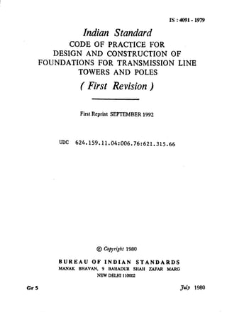
  • 8. Is : 4091- 1979 5. GENERAL DESIGN CRITERIA 5.1 General Design Criteria for Footings in Soils 5.1.1 Normally the following load(s) are given at the ground levels: a) Downward load, b) Uplift load, c) Horizontal thrust, and d) Overturning moments. 5.1.2 Inclined loads shall be split up into vertical and lateral loads at the top of footings ( lateral load is also sometimes called a shear ). 5.1.3 The uplift loads are assumed to be resisted by the weight if the footing plus the weight of an inverted frustum of a pyramid of earth on the footing pad with sides inclined at an angle of up to 30” with the vertical. 5.1.3.1 A footing with an under-cut generally develops uplift resistance of two to three times that of an identical footing without an under-cut (see Fig. IA., Fig. IB and Fig. IC ). However, for design putpose,’ the 2O”and 30” cone assumption shall be taken with a factor of safety of 1.00 for under- cut footing, and 1.5 for footings without an under-cut. 5.1.3.2 A 30” cone shall be taken for an average firm cohesive material. 5.1.3.3 A 20” cone shall be taken for non-cohesive materials, ruch as sand and gravelly soils. 5.1.3.4 For footings below water table, submerged weight of the soil shall be taken. 5.1.4 Alternative footing designs with or without under-cut should be provided where field investigations have not been made to detcrminc the feasibility of under-cutting. 5.1.5 In enlarged footings without an under-cut where individual footing is not provided under each leg and where a combination of uplift loads with lateral loads occurs, the suitability should be checked by the following criteria: a) The resultant of forces acting vertically and laterally should act at a point in its base at a distance of one.sixth of its width from the toes; b) The weight of the footing acting at the centre of the base; and c) Mainly that part of the cone which stands over the heel causes a stabilidng moment. However, for design purposes, this may be taken equal to half the total weight of the cone of earth acting ovet the base. It shall be assumed to act through the tip of the heel. 7
  • 9. RESISlANCE AOAINST UPLIFT B” WEIGHT Of FRUSTUM OF EARlH PLUS WEIGHT GF CONCREIE IA Conventional Assumption RESISTANCE AGAINST UPLIFT BY WEIGHT OF BACKFILL PLUS FRICTION ON FACE OF EXCAXA71ON LINES PLUS WEIGHT OF CONCRETE (APPROXIMATELY EQUAL TO CONVENTIONAL ASSUMPT1ONl IB Actual Action Without Under-Cut .RESISlANCE AGAINST UPLIFT RV VERTICAL COMPONENTS OF SOIL STRESSES A7 FAJLURE ALONG PLANE OF RUPTURE PLUS WElGlI? OF CONCRETE (APPROXIMAIELV EGUAl TO DOUBLE THE CONVENTIONAL ASSUHP7ION) IC Actual Action with Under-Cut FIG. 1 SOILRESISTANCETOUPLIFT 8
  • 10. IS : 4091- 1979 5.1.6 Depending upon the relative magnitude of upward or downward vertical loads, lateral load and overturning moment, footings in soil shall be as classified in Table 1 according to their suitability. 51.7 Bored piles with enlarged bases usually provide an economical type of footing in many soils where under-reaming is possible. In expansive type of soils such as black cotton soils, they have to be carried down to a depth of 3.5 m in deep layers of these soils to counteract the effect of upthrust due to swelling pressure introduced ‘in the soil. Normal type of independent spread footing carried down to shallow depths will not be suitable in such soils, 5.1.8 Different types of piles can be used depending upon the location and in case of heavy uplift forces and moments multiple under-reamed piles or anchors may be used. In case of loose to medium sandy Soilsbored com- paction under-reamed piles may be used. 5.1.9 The piles in uplift should be designed by the usual considerations of the friction on stem and bearings on the annular projections. A factor of safety of 3 may be applied for safe uplift. 5.1.10 The load carrying capacity of an under-reamed pile may bc deter- mined from a load test as given in IS : 2911 (Part IV) - 1979*. In the absence of actual tests, the safe loads allowed on piles under-reamed to 2.5 times the shaft diameter may be taken as given in Table 2. 5.1.10.1 The safe loads given in Table 2 apply to both medium com- pact sandy soils and clayey soils of medium consistency. For dense sandy ( N> 30 ) and stiff clayey ( N> 8 ) soils the loads may be increased by 25 percent. However, the values of lateral thrust should not be increased unless stability of top soil ( strata to a depth of about three times the stem diameter ) is, ascertained. On the other hand a 25 percent reduction should be made in case of loose sandy ( N( 10) and soft clayey ( N94 ) soils. NOTE-For determining the average ‘N’ valuei ( the standard penetration test values ) a-weighted average shall bc taken and correction for fineness under water table shall be applied where applicable. 5.1.10.2Load carrying capacity from soil properties a) In case of clayey soils the ultimate load bearing capacity of an under-reamed pile may be worked out from the following cxprcs- sion: Qll = AP.Nc. C’p+ Aa NC C’a + C’a A’, + a Cs .4# where QU= ultimate bearing capacity of the pile, in kg; AP ~3 cross-sectional area of the pile stem at toe, level in cm”; *Code of practice for design and construction of pile foundations: Part IV Load test on piles. 9
  • 11. IS : 4091-1979 No - bearing capacity factor usually taken as 9; CP = cohesion of the soil around the toe, in kgf/cma; A a = x/4 (Da”-. D2 ) where Dn and D ire the under-reamed C’.a - Als = OS= cs = A8 = bblb’and the &em diameter respectively, in cm; average cohesion of soil around the under-reamed bulbs, in kgf/cm2; surface area of th& cylinder circumscribing the under- reams, in cm2; reduction factor (usually 0.95for clays ); av;;fynThesion of the soil along the pile stem, in kgf/ I surface area of the stem, in cm2. The expression given in 5.1.10.2 holds and for the usual verti- cal spacing between under-reamed bulbs riot greater than 1.5 times the diameter of the under-reamed bulb. b) In case of sandy soils the ultimate load carrying capacity of an under-reamed pile may also be worked out by the following cxpres- sion: Qa=;@- [ r-n 0”) dDunYNy+yNaXdr + r=l 1 where DU= diameter of under-reamed bulb, in cm; D = diameter of stem in cm; n = number of under-reamed bulbs; y = average field density of soil in kg/cmS; Ny and Nq = bearing capacity faetors depending ‘on the angle of intcr- nal friction [ for values Ny see IS : 6403-1971* and N,-,, see IS : 2911 ( Part III )-1980t 1; n, = depth of the centre of different under-ream bulbs in cm; 4ir= total depth of pile in cm; K = earth pressure constant ( usually 1.75 for sandy soils); 8 = angle of wall friction; CI,= depth of the centre of the first under-ream bulb in cm; and 4, = depth of the centre of last under-ream bulb in cm. *Code of practice for determination of allowable bearing pressure on shallow foundation. *Code of practice for design and construction of pile foundations: Part III Under- reamed piles (first revision) . 10
  • 12.
  • 13. As in the Original Standard, this Page is Intentionally Left Blank
  • 14.
  • 15. As in the Original Standard, this Page is Intentionally Left Blank
  • 16. IS:4091-1979 5.1.10.3 In case of piles resting on rock the bearing component will be obtained by multiplying the safe capacity of rock with the bearing area of pile stem plus the bearing provided by the under-ream portion. 5.2 Allowable Bearing Pressure- The allowable bearing pressure of the soil where the towers or poles are founded shall be based on adequate subsoil exploration and. testing carried out in accordance with IS : 188%1971*, IS : 1892-1979t and IS : 1904-1978:. The permissible bearing pressure so arrived may be exceeded at the edges of footings by 25 percent when variation in the intensity of the reaction caused by the transmission of moments to the footing is taken into account. 5.3 Permissible Stresses in Concrete and Reinforcement- Where stresses due to wind, temperature and shrinkage. effects are combined with those due to dead,’ live and impact loads, stresses specified in IS : ‘456-1978s for these conditions should be used in the design. 5.4 Structural Safety 5.4.1 For the structural safety against sliding, overturning and for the footings at different levels provisions laid down in IS : 19&l-1978$ shall apply. 5.4.2 The depth of footings shall conform to the provisions laid down in the relevant Indian Standards depending on the type of foundation [ see IS : 1080-198011,IS tlS04-1978$, IS : 2911 (Part I/Set I)-19797, IS : 2911 ( Part I/Set 2 )-I9797 and IS : 2911 ( Part T/Set 3 )-19791 1. 5.5 Footing on Rock 5.5.1 A rock footing, for uplift and horizontal loads, may be considered to develop strength by the dead load of the concrete and. the strength of bar anchorage ( the pull-out value of anchor bars grouted in drill holes or the failure strength of rock engaged by bars). 5.5.2 The depth of embedment of the bars below the bottom of the foot- ing should not be less than the following: D=45d -___- *Method of load tests on soils (Jlrst revision). tCode of practice for subsurface investigations for foundations (jfirstrevision ). fCode of practice for structural safety of buildings : Shallow foundations ( secondrevision). $Code of practice for plain and reinforced concrete ( third revision ). IjCode of practice for design and construction ofsitnple spread foundatiods (Jirst revision). TCode of practice for design and construction of pile foundations, Part I Concrete piles: Section 1 Driven cast in-situ piles; Section 2 Bored cast in-situ piles. Section 3 Driven precast piles. 15
  • 17. Is:4091~1979 where D A the minimum depth of embedment in mm, and n = diameter of anchor bar in mm. 5.5.3 The spacing of embedded bars 1should normally be one-haIf of the normal depth of embedment- as given in 5.5.2. 5.5.4 The size of the bar shall be governed by the criterion that com- bined stresses do not exceed the permissible limits. 5.6 Concrete Piles-In case concrete piles ( other than under-reamed ) the provisions of IS : 2911 ( Part I/Set l )-1979*, IS : 2911 ( Part ISec 2 )- 1979* and 1s : 2911 ( Part 1,Bec 3 )-1979* shall apply. 5.7 Special Cokiderations 5.7.1 Footings in Seismic Zones - In designing footings in seismic zones, the provisions of IS : 1893-1979t shah apply. 5.7.2 Footings in Sdphate Bearing Clays - Suitable precautions’ as laid down in IS : 1080-19621 shall be taken in the case of footings in sulphate bearing clays. 5.7.3 In the case of river crossing, the horizontal pressure due to forces of water current shall be considered in the design. NOTE - Towers located in river are likely to be subjected to shock loads,due to float- ing debris. The towers should be suitably protected against such shocks. 5.7.4 Excavations, Drillilzg and Blasting- These operations shall con- form to IS : 3764-1966$, and IS : 4081-196711. 5.7.5 In case the footings under the same tower structure happen to rest such that’some of them are in soil and the rest on rock then the consideration shall be given for differential settlement and the structural safety. 5.7.6 In case of deviations in the alignment of the Iine, modifications should be made in the design of foundations for towers. No special pro- visions may be necessary for deviations up to 2”. 5.8 Concreting - Concreting shall be done in accordance with the relevant requirements given in IS : 456-19787. *Code of practice for design and construction of pile foundations: Part I Concrete piles : Section 1 Driven cast in-situ piles. Section 2 Bored cast in-situ piles. Section 3 Driven precast piles. iCriteria for earthquake resistant design of structures ( thirdreuision). tCode of practice for design and construction of simple spread foundations. $Specification for safety code for excavation work. &Specification for safety code for blasting and related drilling operations. TCode of practice for plain and reinforced concrete ( thirdrevi&on). 16
  • 18. IS : 4091- 1979 6. STAY SETS 6.1 The stay set may be provided by burying a 30 x 30 cm and 5 mm thick mildsteel plate having a 18 x 18 mm hole in the centre through which n 16 mm diameter bolt passes. 6.2 As an alternative to the steel plate in 6.1, cleats formed by two 30 cm long pieces of angle iron of size 50 x 50 x 15 mm buried in a concrete pad of 15 cm can also be provided. 7. POLES 7.1 The foundation for poles is provided by a certain length of the pole buried into the ground. The bearing capacity in compression is mainly derived by the skin friction on the surface of the poles and to a smaller extent by the base area. Under the action of wind the lateral loading in- troduces moments and lateral thrust ‘on the foundation. 7.2 Depth of embedment of the pole for the purpose of foundation should not bc less than one-sixth of the total length of the pole above ground level. 7.3 A protective collar providing a concrete cover of not less than 10 cm around the pole shall be provided. The depth of the concrete collar below the ground level should not be less then 45 cm and it should be atleast 15 cm above the ground level. 17
  • 19. BUREAU OF INDIAN STANDARDS Headquarters: Manak Bhavan, 9 Bahadur Shah Zafar Marg, NEW DELHI 110002 Telephones: 331 01 31, 331 13 75 Telegrams: Manaksanstha ( Common to all Offices) Regional Offices: TeJepbone Central : Manak Bhavan, 9 Bahadur Shah Zafar Marg, 331 01 31 NEW DELHI 110002 331 13 75 *Eastern : l/l 4 C. I. T. Scheme VII M, V. I. P. Road, ’ 36 24 99 Maniktola, CALCUTTA 700054 Northern : SC0 445-446, Sector 35-C, I 21643 CHANDIGARH 160036 3 1641 I 41 24 42 Southern : C. I. T. Campus, MADRAS 600113 41 25 19 41 2916 TWestern : Manakalaya, E9 MIDC, Marol, Andheri ( East ), 6 32 92 95 BOMBAY 400093 Branch Offices: IPushpak’. Nurmohamed Shaikh Marg, Khanpur. I 2 63 48 AHMADABAD 380001 2 63 49 SPeenya Industrial Area 1st Stage, Bangalore Tumkur Road 38 49 55 BANGALORE 560058 I 38 49 56 Gangotri Complex, 5th Floor, Bhadbhada Road, T. T. Nagar, 667 16 BHOPAL 462003 Plot No. 82183. Lewis Road. BHUBANESHWAR 751002 5315. Ward No. 29, R.G. Barua Road, 5th Byelane, GUWAHATI 781003 5 36 27 3 31 77 5-856C L. N. Gupta Marg ( Nampally Station Road ). HYDERABAD 500001 23 1083 R14 Yudhister Marg, C Scheme, JAIPUR 302005 { 6 34 71 6 98 32 117/418 B Sarvodaya Nagar, KANPUR 208005 ( 21 68 76 21 82 92 Patliputra Industrial Estate. PATNA 800013 6 23 05 T.C. No. 14/l 421. University P.O.. Palayam I6 21 04 TRIVANDRUM 695035 16 2117 /nspection Offices ( With.Sale Point ): Pushpanjali, First Floor, 205-A West High Court Road, 2 51 71 Shankar Nagar Square, NAGPUR 440010 Institution of Engineers ( India ) Building, 1332 Shivaji Nagar, 5 24 35 PUNE 411005 *Sales Office in Calcutta is at 5 Chowringhee Approach, P. 0. Princep 27 68 00 Street, Calcutta 700072 tSales Office in Bombay is at Novelty Chambers, Grant Road, 89 66 28 Bombay 400007 $Sales Office in Bangalore is at Unity Building, Narasimharaja Square, 22 36 71 Bangalore 560002 Reprography Unit, BIS, New Delhi, India