Transmission and distribution line design final
•Transferir como DOCX, PDF•
31 gostaram•16,656 visualizações

Transmission Line designed on basis of data available for a given Hydropower system. Looking this document you can yourself design the Transmission Line system.

Recomendados
Recomendados
Mais conteúdo relacionado
Mais procurados
Mais procurados (20)
Destaque
Destaque (20)
Semelhante a Transmission and distribution line design final
Semelhante a Transmission and distribution line design final (20)
Último
Último (20)
Transmission and distribution line design final
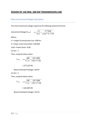
- 1. 1 | P a g e DESIGN OF 130 MW, 200 KM TRANSMISSION LINE Most Economical Voltage Calculation: The most economical voltage is given by the following empirical formula: Economical Voltage (V eco) =5.5* 150**cos 1000* 6.1 Nc PLt Where, Lt = length of transmission line =200 Km P = Power to be transmitted =130 MW cosØ = Power factor =0.96 For Nc= 1 Then, using the above values V eco =5.5* 150*1*96.0 1000*130 6.1 200 = 177.137 KV Nearest Standard Voltage= 220 kV For Nc= 2 Then, using the above values V eco =5.5* 150*2*96.0 1000*130 6.1 200 = 132.587 KV Nearest Standard Voltage= 132 kV
- 2. 2 | P a g e Checking technical criterion: For Nc=1 Surge impedance Loading (SIL) = V2 /Z0 = 2202 /400 =121 Multiplying factor (MF) = SIL P max = 130/121 = 1.0834 MFlimit for 160 KM from provided standard table = 2.0614 MFcalculated (1.08) < MFlimit (2.0614) Power transfer capability = MFlimi* SIL =2.0614*121 =249.4294 For Nc=2 Surge impedance Loading (SIL) = V2 /Z0 = 1322 /200 =87.12 Multiplying factor (MF) = SIL P max = 130/87.12 = 1.4921 MFlimit for 160 KM from provided standard table = 2.25 MFcalculated (1.1921) < MFlimit (2.0614) Power transfer capability = MFlimi* SIL =2.0614*87.12 =179.58 Since the power transfer capability for double circuit is near to the power to be transferred . s so Nc=2 is taken in this design. Since the voltage level 132Kv is not meet the voltage regulation for any conductor available. So we have to chose double circuit 220 KV.
- 3. 3 | P a g e Calculation of Insulation Discs For all the calculations of number of insulator discs, we considered following value of different factor: FOWR = Flashover Withstand Ratio =1.15 NACF = Non Atmospheric Condition Factor = 1.1 FS = Factor of Safety =1.2 1) Number of Insulator Discs Required for the temporary O/V Temporary O/V = Earth Factor (EF) * Maximum system voltage = 0.8 * (220*√2 * 1.1) = 273.7917 KV Equivalent Flashover Voltage (Veq= Temporary O/V * FOWR *NACF * FS Equivalent Voltage (Veq) = 273.7917* *1.15 * 1.1 *1.2 = 415.6158 KV From standard table number of insulator discs required to withstand above equivalent voltage (Na) = 11 2) Number of Insulator Discs Required to withstand continuous operating voltage: a) Voltage Level for dry condition = Equiv dry 1 min. voltage*FOWR*NACF * FS Where, Equivalent dry 1 min voltage is taken from standard table = 435 KV Equivalent 1 min dry flashover Voltage = 265 * 1.15 * 1.1 *1.2 = 660.33 kV From Standard Table number of discs required to withstand above equivalent voltage level (Nb1) =12 Voltage Level for given Power Transmission =220 KV Number of Circuit = 2 Power Factor ( cosØ ) = 0.96 Length of Transmission Line (L) = 200Km
- 4. 4 | P a g e b) Voltage Level for Wet condition = Equiv dry 1 min. voltage*FOWR*NACF * FS Where, Equivalent wet 1 min voltage is taken from standard table = 395 KV Equivalent Voltage Level = 395* 1.15 * 1.1 *1.2 = 599.61 KV From Standard Table number of discs required to withstand the above equivalent voltage level (Nb2) =9 3) Number of Insulator Discs required for switching over voltage: Voltage Level = switching o/v * Switching to impulse ratio * FOWR *NACF* FS Where, Switching to impulse ratio (SIR) = 1.2 SSR = Switching Surge Ratio =2.75 Switching O/V =SSR* ( 2 / 3 )*Max system voltage*SIR So Switching O/V =652.0541KV Equivalent flashover Voltage Level = 652.0541*1.15*1.1*1.2 = 989.8182 KV From Standard Table number of discs required to withstand the above voltage level (Nc) = 11 3) Number of Insulator Discs required for over voltage due to Lightning: From standard table Equivalent voltage level for the given system voltage =900 KV Equivalent flashover Voltage Level = 900* FOWR *NACF* FS = 900*1.15*1.1*1.2 = 1366.2 From Standard Table number of discs required to withstand the above voltage level (Nd) = 16
- 5. 5 | P a g e Hence from above table the required number of insulator discs to withstand all types voltage level in all condition for given system voltage = 16 Air Clearance Calculation Air clearance parameters calculation for double circuit tower configuration: a = minimum distance (clearance requirement) from a line conductor to any earthed object, and is given by the following relation: a =6.5 inch per 10 KV (rms) =(6.5*220*1.1)/( 10*3 )+8 =98.8171 inch =250.995cm =2.5099m SN Voltage Level Description Voltage Level Number of Discs 1) 2) 3) 4) Temporary O/V appearing across the insulator Continuous voltage i) Continuous operating Voltage in Dry condition ii) Continuous operating Voltage in Wet condition Switching Over voltage O/V due to lightning 415.6158KV 660.33KV 599.61 KV 989.8182KV 1366.2 KV 11 12 9 11 16 Required Number of Insulator Discs =16
- 6. 6 | P a g e Now String Length (l) = 2 a =3.5495m Tower width (b) = 1.5*a = 3.7648m Cross arm length(CL) = 2*a = 5.0198m Vertical distance between two adjacent line conductor (y) = 22 2 1 )( a al y x al Where 0.25 < x/y< 0.333 = 2 2 5099.2*2 5099.25495.3 25.01 )5099.25495.3( = 6.3557m Horizontal distance between adj. conductor =5.5 a = 5.5*2.5099 =13.804 m Height of earth wire from top (d) = = 5.14504m Conductor and Tower Selection Conductor and Tower Selection Line current is calculated as: Air clearance from earthed object (a) = 2.5099 m String Length (l) = 3.5495 m Tower Width (b) = 3.7648m Cross Arm Length = 5.0198m Vertical distance between two adjacent line conductor (y) = 6.3557m Horizontal distance between two adj. line conductor =13.804 m Height of Earth wire from top cross arm (d) = 5.14504m
- 7. 7 | P a g e Line current (I) = cos**3 2/ llV P = 96.0*220*3 1000*)2/130( = 177.688 amp Comparing this value of the current with the current carrying capacity from the given standard ASCR conductor table, Conductor “FERRET” is selected. For Ferret conductor, From ASCR conductor table, Resistance at 200 C (R20) = 0.67950 Ώ/Km Coefficient of Resistivity (α20) = So Resistance at 650 C (R65) = R20 (1 + α20(65-20)) = 0.67950 (1+0.004*45) = 0.80181Ώ/Km Transmission Efficiency Criterion Power Loss for single conductor = I2 *R*L = (177.688)2 *0.80181s*200 = 5.063MW/conductor Transmission Efficiency (ή) = 65 / (65+3*5.063) = 0.8105 = 81.058% Transmission Efficiency<94 %. So this conductor is not used used . To get higher efficiency we proceed in same way and calculate efficiency finally we got the conductor “Wolf” which has efficiency 94.036%. Voltage Regulation Criterion For Conductor Wolf, This conductor has 37 strands 7Aluminum strands and 1steel strands. Diameter of each strands = 2.59mm Conductor diameter (D)=18.13mm Radius of the conductor(R)=9.065mm GMR for inductance (GMRi) =0.768R =6.1692smm
- 8. 8 | P a g e GMR for capacitance (GMRc) = R =9.065mm Geometric mean distance(GMD)= = =8.00768m Resistance of the whole line (R) = 43.518 Ώ Inductance of Whole length (L) =2 * 10-4 ln (GMD/GMRi)*L =2e-4*ln(8.00768/ )*200 =0.2867H Capacitance of whole Length(C) = 3** ln 2 eL GMRc GMD = =1.640µF Now Impedance of the Line (Z) = R + j 314.15 *L = 43.518+j90.0694 = 100.031<64.211 Susceptance of the Line (Y) = j314.15*C = j5.1522* e-04 = (5.1522* e-04) <90 A, B, C, D parameters calculation A = 1 + ZY/2 = 0.9768<0.657 B = Z= 100.031<64.211 C= Y (1+ZY/4) D = A Now, Sending end Voltage (Vs) = A*Vr +B*Ir = 0.9768<0.657* 220*e3/√3<0 + 100.031<64.211* 177.688<-16.26
- 9. 9 | P a g e = 12.407*e4<0.657+17.774*e3<47.951 = 136.7502<6.1377KV Now Voltage Regulation = (|Vs|/A -|Vr| )/|Vr| = 0.1021 = 10.219% Voltage regulation < 12% so this conductor Wolf can be used. Corona Inception Voltage Criterion For wolf conductors Corona Inception voltage (Vci) = *21.1*GMR*m*δ*ln(GMD/GMR) Where, m = factor of roughness =0.9 δ = relative density of air =.95 Vci = 21.1 * 0.9065*0.9*0.95* ln (8.00768/9.065e-3) = 192.152KV Here Vci < Vs so Corona Inception Voltage criterion is met. So we go for next higher conductor. For conductor Panther GMRc=10.5mm GMD=8.00768m Vci= 21.1 * 1.05*0.9*0.95* ln (8.00768/10.5e-3) =217.748KV For conductor Lion GMRc=11.13mm GMD=8.00768m Vci= 21.1 * 1.113*0.9*0.95* ln (8.00768/11.13e-3) = 228.787KV Since Vci>Vs for conductor Lion. So no corona occurs in that conductor.
- 10. 10 | P a g e Tension Calculation for Different Conductors with Different Span in Different Condition Four Different conductors below conductor LION in ASCR conductor table is chosen. Hence Tension calculation will be done for conductor “lion, Bear, Goat , Sheep and Dear” with Span length 250 m, 275 m, 300 m, 325 m, and 350 m. Tensions for Toughest, Stringing and Easiest condition are calculated and tabulated below. Sample calculation is also shown. Sample calculation; Conductor 1: Lion Area of conductor = 2.94 cm2 Linear expansion coefficient = 1.773 e-5 per 0 C Modulus of elasticity (E) = 7.87 e+5 kg/cm2 Tension at toughest condition (T1) = = = 5105Kg. Weight of conductor (wc) = 1097Kg/Km Wind pressure (Fw) = 100 kg/m2 Weight due to wind force (ww) = Fw*d*(2/3) =100*1000*22.26e-3*2/3 = 1484kg Weight of ice (wice) = 0 Weight for toughest condition (w1) = = 1845.444 kg Weight for the stringing and easiest condition (w2) = 1097kg. Then, the tension at stringing (T2) and the easiest condition (T3) is calculated using the following equation known as STRINGING EQUATION. T2 2 [T2+k1] - k2 = 0 ………………………………….. (1)
- 11. 11 | P a g e Where, AE T LW AETK 2 1 22 1 1 24 121 and, K2= AE LW 24 22 2 . From the above data, the values of K1 and K2 for the span of 250m are given by: K1 = -3210.60; K2 = 7.25e+9; Using the stringing equation, the value of T2 is found to be, T2 = 3731.26 kg. Similarly, T3 is calculated by the similar procedure as above. For the calculation of T3 the value of K1 and K2 for 250 m of length are given by: K1 = -903.54; K2 = 7.25e+9; Using the stringing equation, we get the value of T3 as: T3 = 2288.303 kg. In the similar manner, the values of tensions of different conductor for different span length is calculated and presented in the table below:
- 12. 12 | P a g e Sag and height of tower calculation We have the relation, Maximum sag (Dmax) = (W L2 )/ (8*T3); Where, W = weight of conductor. L = length of span. T3 = tension at easiest condition. Sample calculation: For Lion, W = 1097kg/km. L = 0.25 Km. T3 =2288.303Kg. Using the above equation, Dmax = 3.74527m. Let the minimum ground clearance (hg) = 7.5m. Height of lower conductor (H1) = hg+ Dmax =11.2452m. Height of middle conductor (H2) = H1+y = 17.60m. Height of top most conductor (H3) = H2+y = 23.956m. Total height of tower (Ht) = H3+l+d = 32.6512m. Similarly, the maximum sag, H1, H2, H3 and the total height of the tower are calculated and presented in the table below: Earth wire selection From earth wire table, earth wire GUINEA is chosen as follows: No of strands = 19; diameter of a strand = 2.92mm; weight of conductor = 590kg/km; Conductor diameter = 14.60mm; conductor area = 127.20mm2 ; Ultimate tensile strength = 6664 kg; Hence, maximum tension (Te) = 6664/2 = 3332 kg. Bending moment and tower weight calculation Sample calculation: for Lion, Ht=32.6512m, 250m span Taking 80% for tower A; 15% for tower B; and 5% for tower C Due to Earth wire 1) Bending moment acting on tower due to E/W considering wind force:
- 13. 13 | P a g e BMe1 = Fwe*Ht*Ne = (100*14.60e-3*250*2/3)*32.6512*2 = 15890.2506 kg-m. 2) Bending moment due to turning of the E/W BMe2=Fte*Ht*Ne = BMe2 = 2*Te*(sin10 *0.80 + sin7.50 *0.15 + sin150 *.05)*Ht*2 =2*3332*(0.046481)*32.6512*2 = 20227.378Kg-m Due to power conductor 1) Bending moment acting on tower due to power conductor considering wind force BMpw = Fw*(H1+H2+H3)*2 = (100*22.26e-3*250*2/3)*(11.2452+17.60+23.956)*2 = 39178.4904 kg-m 2) Bending moment due to turning of the power conductor BMpt = 2*T1*(sin10 *0.80 + sin7.50 *0.15 + sin150 *.05) *(H1+H2+H3)*2 = 2*5105*0.046481*52.8012*2 =50117.261kg-m Then the total bending moment is calculated as; BMtotal = BMe1 + BMe2 + BMpw +BMpt =125413.38 kg-m Weight of tower Weight of tower (Wt) = ; Where, Ht is in Ft; BM is in lb-ft. =0.000631*Ht* ; where, Ht is in m; Bm is in kg-m. The bending moment of different conductors at different length of span and weight of tower are calculated and shown in the tabulated form below:
- 14. 14 | P a g e
- 15. 15 Cost per unit length calculation Assumptions: Cost of the steel used in tower = Rs.150000 per tonne Number of towers (Nt) = ((total length)/(length of span))+1 Cost of tower per unit length = (cost per tower*Nt)/length of transmission Sample calculation: For Lion; 250m; weight of tower= 10.30955 tonne Number of tower = (200/0.25 ) +1= 801 nos Cost per tower = cost per tonne* weight of tower = Rs.150000*10.3185 = Rs. 1547775 Cost of tower per unit length = (1547775*801)/200 = Rs.6198838.875 Similarly the cost of tower per unit length of different conductor and different span are shown in table below: Most economical span and conductor selection Data available; Cost of aluminum per tonne = Rs.20150 Cost of steel per tonne = Rs. 150000 Sample calculation: For Lion; span =325m; aluminum weight per Km = 659 kg; steel weight per km = 438 kg Cost of power conductor Cost of aluminum per km = Rs. 20150*0.659 = Rs.13278.85 Cost of steel per km = Rs 150000*.438 = Rs. 65700 Total Cost of power conductor = (Rs. 13278.85 + Rs. 65700)*6 = Rs.473873.1/km From table above, Tower cost per unit length = Rs. 5915213.448
- 16. 16 Capital cost/length = conductor cost/km + tower cost/km = Rs.473873.1+ Rs. 5915213.448 (P) =Rs. 6389086.548 Annual capital cost (A) is calculated as: A= Where i=10% and n=25 years This gives annual capital cost (A) = Rs. 703873.348 Power loss per Km PL=27.338 Kw; load loss factor (LLf)=k1*LF+K2*LF^2 = (0.2*0.5)+(0.8*0.5*0.5) =0.3 Cost of Energy loss/Km = PL *LLf * time* rate per Kwh =27.338*0.3*365*24*7.5 =Rs. 538831.98 Total annual cost = Rs. 703873.348+ Rs. 538831.98 =Rs. 1242705.328 The total annual cost calculation is shown in table below: From the above table, The minimum total annual cost is acquired by the conductor Sheep. Hence we go for the conductor Bear for the transmission line of 130 Mw and 200Km.
- 17. 17 Transmission line characteristics of the conductor Sheep Electrical characteristics 67 strands with 7 Steel strands and 32Aluminum strands. Diameter of each strands = 3.99 mm GMR for inductance (GMRi) = 10.7251mm GMR for capacitance (GMRc) =13.965mm Resistance of the whole line per phase(R) = 18.3395Ώ Inductance of Whole length (L) =0.264H Capacitance of whole Length(C) = 1.7517 μF Now Impedance of the Line (Z) = 84.9414<77.531 Ώ Susceptance of the Line (Y) =j5.5031*e-04 siemen = 5.5031*e-04<90
- 18. 18 A, B, C, D parameters calculation A = 1 + ZY/2 = 0.979<0.2711 B = Z= 84.9414<77.531 C = 5.440*e-04<90.146 D = A=0.979<0.2711 Now, Sending end Voltage (Vs) = A*Vr +B*Ir = 0.979<0.2711* 220/√3<0 + 84.9414<77.056* 177.688*e-03<-16.26 = 132.4296<5.9652KV Sending end current(Is) = C*Vr +D*Ir = 168.563<7.2185 Now Voltage Regulation = (|Vs|/A -|Vr| )/|Vr| = 0.0649 = 6.497% Corona Inception Voltage Criterion Corona Inception voltage (Vci) =21.1*GMR*m*δ*ln(GMD/GMR) Where, m = factor of roughness =0.9 δ = relative density of air =0.95 Vci = 21.1 * 1.3965*0.9*0.95* ln (8.00768/13.965e-3) = 277.161KV
- 19. 19 Mechanical characteristics Length of span =350m. Tension at toughest condition = 7955kg Tension at stringing condition = 5902.87kg Tension at easiest condition = 3923.8231kg Heights: Maximum sag =6.73561 m; H1=14.2356m; H2=20.591m; H3=26.947m; Ht=35.6415m Bending moment =178830.9kg-m Tower weight=14.3985 tonne Tower Cost per unit length=Rs.6187763.968 /Km Total annual cost =Rs. 1106280.389/km