1. Electronics design pcb
production
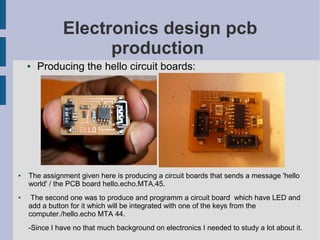
● Producing the hello circuit boards:
● The assignment given here is producing a circuit boards that sends a message 'hello
world' / the PCB board hello.echo.MTA.45.
● The second one was to produce and programm a circuit board which have LED and
add a button for it which will be integrated with one of the keys from the
computer./hello.echo MTA 44.
-Since I have no that much background on electronics I needed to study a lot about it.
2. Electronics design production
● Sending it to the modella machine:
First I opened the Cad py
file and opened a hello 45
then opened a file from the
input tool path.
I uncommented the
highresolution for
machining.Then on the
CAM tool I opened the
machine i.e. a modella
machine.
Then I selected the tool
diameter with 1/64 for
cutting, speed x4,y4,
contours -1 and changed
the tool on the machine just
as I set it on the CAD. Since
I my board is sticked in the
corner I put the position
x2y2. After contouring I sent
it to the machine.
3. PCB Production
● Components and Materials needed:
After printing the board I changed the setting
and tool diameter by 1/32, to cut it. After I made
the board out I collected the components.
Components:
● 1. The printed circuit board
● 2.microcontroller = tiny 45
3.capacitor = C1 3.3UF
● 4. Resistor = R1 10K
● 5.voltage regulator=IC 2
● 6. connectors=4 & 5 legged
Materials:
● Soldering iron
● Soldering wire
● Copper for cleaning brass and Clip
4. PCB Production
● Soldering
1. Stick the circuit board to your table by double sided tape -but not tightly because if it is tight it
might be impossible for you to change the direction during soldering.
2. According to our/fablab Bcn experience, the best way to join the components to the circuit
board is to melt and drop the soldering wire on each point of *the circuit board first. This is
because the wires will melt so quickly that you cant fix it no matter you tried to be quick.
3. Stick each components carefully *on the tip of each drop and press the component's
leg/tip by the solering iron. If you think the legs are not fixed well you can add more drops
of soldering wire on the top of its leg.
5. Embeded Programming
● Producing the LED circuit board:
First I opened the Cad py
and input a hello 44.MTA.cad
for printing the board. Then used
a setting the same way like
the hello 45 MTA. Downloaded from
http://fab.cba.mit.edu/about/fab/
After the production I needed to
assemble the components.
6. ● Producing Electronics
1. Microcontroller- Tiny 44
2. Resistor1- R10K
3. Resistor2- R 1K
4. Resistor3- R 4.99
5. Capacotor- 3.3UF
6. Voltage Regulator- 5V
7. Resonator -20 MHZ
8. D1- 4.7v
9. D2- LED
10.The printed circuit board
● On this part being aware of the polarity of the capacitor, LED and the resonator is very
important, there is a line to distinguish that. I have been changing the direction and
when programming it will not even read your board or the connection.
7. ● Programming with Cad
There are 3 fundemental steps
-Sending the power to the circuit board
through the serial port,
-Sending the information from the
the computer to the board through the
parallel port,
-Reading the programmed information
from the board/ 'mini computer' through the
serial port.
● Adding the button:
● This part was the hardest for me and still is because after making my third circuit
board it doesnt work yet. I am still working on it so I hope after many trials i will
sucseed.