
Recomendados
Recomendados
Mais conteúdo relacionado
Mais procurados
Mais procurados (8)
Semelhante a 5sfe engine removal
Semelhante a 5sfe engine removal (17)
5sfe engine removal
- 1. 4A-FE & 5S-FE Engines 1. Disconnect the negative battery cable. Remove the battery. 2. Mark and remove the engine hood. Remove the engine under covers. 3. Raise and safely support the vehicle as necessary. Relieve the fuel pressure. Drain the engine oil and coolant. Remove the air cleaner assembly along with its hose and any attachments. 4. Disconnect the accelerator and throttle cables at the bracket. 5. Remove the lower cover from the relay box. Disconnect the fusible link cassette and connectors. Remove the engine relay box from the battery. 6. Remove the air conditioning relay box from the bracket. On the 5S-FE engine remove the cruise control actuator assembly. 7. Remove the coolant reservoir tank. Remove the radiator (disconnect transaxle cooling lines if so equipped) and cooling fan. 8. On the 5S-FE engine remove the two wiper arms and outside lower windshield molding. Remove the suspension upper brace. 9. On the 5S-FE engine, remove the ignition coil assembly. Disconnect the check connector, igniter connector (5S-FE engine), vacuum sensor connector and ground strap from the left front fender apron. Remove the engine wiring bracket. Disconnect the noise filter assembly. 10. Mark and disconnect the vacuum hoses at the charcoal canister. Remove the charcoal canister. 11. Disconnect the heater hose from the water inlet and speedometer cable. 12. Disconnect the fuel hose. Recover all leaking fuel in a suitable container. 13. On models with a manual transaxle, remove the clutch release cylinder and position it out of the way with the hydraulic lines still attached. 14. Disconnect the shift control cables from the transaxle. 15. Mark and disconnect the following hoses: vacuum sensor hose from the gas filter on the air intake chamber, brake booster vacuum hose, air conditioning vacuum hoses on air intake chamber and air conditioning hose from air pipe (4A-FE engine). 16. Disconnect two cowl wire connectors and engine wire clamp from engine fender apron. 17. Mark and disconnect the following engine wiring from the cabin: engine ECU connector, cowl wire connectors, air
- 2. conditioning amplifier connector and O/D diode connector (4A-FE engine). 18. Remove the suspension lower crossmember. 19. Disconnect the oxygen sensor connector. Remove all necessary brackets and retaining bolts. Remove the front exhaust pipe assembly. 20. On vehicles equipped with automatic transaxle, disconnect control cable from engine mounting center member. 21. Remove the front halfshaft assemblies as required from the vehicle. 22. Remove the drive belt. Unbolt the air conditioning compressor (if so equipped) and then wire it out of the way with the refrigerant lines still attached. 23. Remove the drive belt and remove the power steering pump assembly without disconnecting the pressure and return hoses. 24. Remove the engine mounting center member. 25. Remove the front engine mounting insulator and bracket. 26. Remove the rear mounting insulator and bracket. 27. Disconnect the ground wire from the fender apron. Remove the ground strap from the transaxle. 28. Remove the right and left engine mounting stay. 29. Slowly and carefully, remove the engine and transaxle assembly from the top of the vehicle. Be careful not to hit the power steering gear housing or the neutral safety switch if so equipped. To install: 30. With a suitable engine crane (always use lifting eyes for removal and installation procedures) install the removed engine/transaxle assembly in the vehicle. Install all engine mounts (insulators) and brackets in the correct location. 31. Raise and safely support the vehicle as necessary. 32. Install the left and right engine mounting stay. 33. Connect the ground wire to the fender apron. Install the ground strap to the transaxle. 34. Install the engine mounting center member. 35. Install the power steering pump assembly. Install the air conditioning compressor assembly. Install drive belts in the correct position. 36. Install the front halfshaft assemblies as required to the vehicle. 37. On vehicles equipped with automatic transaxle connect the control cable to engine mounting center member. 38. Reconnect the front exhaust pipe assembly. Connect the oxygen senor electrical connector. Install all necessary
- 3. brackets and retaining bolts. 39. Install the suspension lower crossmember. 40. Reconnect the following engine wiring to the cabin: engine ECU connector, cowl wire connectors, air conditioning amplifier connector and O/D diode connector (4A-FE engine). 41. Reconnect the two cowl wire connectors and engine wire clamp to the engine fender apron. 42. Reconnect the following hoses: vacuum sensor hose to the gas filter on the air intake chamber, brake booster vacuum hose, air conditioning vacuum hoses on air intake chamber and air conditioning hose to air pipe (4A-FE engine). 43. On models with a manual transaxle, install the clutch release cylinder with the hydraulic lines attached. 44. Reconnect the shift control cables to the transaxle. 45. Connect the fuel hose using new retaining clamps if necessary. 46. Connect the heater hose to the water inlet and reconnect the speedometer cable to the transaxle. 47. Install the charcoal canister and the vacuum hoses to the charcoal canister. 48. Install the engine wiring bracket. Connect the noise filter assembly. 49. On the 5S-FE engine install the ignition coil assembly. Reconnect the check connector, vacuum sensor connector, igniter connector (5S-FE engine) and ground strap to the left front fender apron. 50. On the 5S-FE engine install the two wiper arms and outside lower windshield molding. Install the suspension upper brace. 51. Install the radiator (transaxle cooling lines if so equipped) and cooling fan (connect electrical leads) assembly. Install the coolant reservoir tank in the correct location.
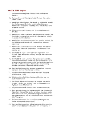
- 4. Disconnecting the transaxle control cables—4A-FE engine Disconnecting the engine harness from the passenger compartment—1990–93 Celica Click to Enlarge
- 5. Removing the engine harness cowl panel cover—1990–93 Celica 52. Install the air conditioning relay box to the bracket. Install the engine relay box to the battery. Reconnect the fusible link cassette and connectors. Install the lower cover to the relay box. On the 5S-FE engine install the cruise control actuator assembly. 53. Reconnect the accelerator and throttle cables at the correct bracket. Install the engine under covers. 54. Install the battery and connect the battery cables. Install the air cleaner assembly and attaching components and engine hood in the correct location. 55. Refill all fluid levels with the correct fluid to the proper level. Bleed systems as necessary. Make all necessary adjustments. Start the engine. Check for any fluid leaks, road test the vehicle for proper operation.
- 6. Removing the cruise control actuator—5S-FE engine shown Disconnecting the heater hoses and speedometer cable—5S-FE engine shown Disconnecting the power steering pump without disconnecting the hoses—5S-FE engine shown