Zeshan Sattar- Assessing the skill requirements and industry expectations for...
Computer network Report
1. COMPUTER NETWORK PROJECT FILE IT-366
PRACTICAL NO. 1
STUDY THE PHYSICAL MEDIA OF CONNECTIVITY
The physical media of connectivity specifies the physical and electrical characteristics of
the connections that make up the network. It is made up of cables, connectors,
repeaters etc. It can be think of a hardware layer totally. When a message is to be
transmitted to some other station in a network the message is created at application
layer and travel through other layers to physical layer. The physical layer gets this
message packet at least, and it only needs to convert the characters of message packet
into electrical signals. This layer does not need to process routing information, compute
addresses, add check bits or other contents of a message packet, as all these jobs are
done by upper layers and then the packet is handed over to physical layer.
Something Related to Physical Media
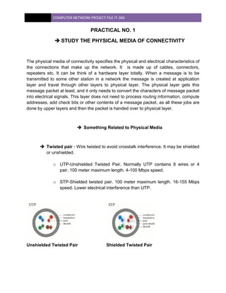
Twisted pair - Wire twisted to avoid crosstalk interference. It may be shielded
or unshielded.
o UTP-Unshielded Twisted Pair. Normally UTP contains 8 wires or 4
pair. 100 meter maximum length. 4-100 Mbps speed.
o STP-Shielded twisted pair. 100 meter maximum length. 16-155 Mbps
speed. Lower electrical interference than UTP.
Unshielded Twisted Pair Shielded Twisted Pair
2. COMPUTER NETWORK PROJECT FILE IT-366
Coaxial - Two conductors separated by insulation such as TV 75 ohm cable.
Maximum length of 185 to 500 meters.
o Thinnet - Thinnet uses a British Naval Connector (BNC) on each
end. Thinnet is part of the RG-58 family of cable*. Maximum cable
length is 185 meters. Transmission speed is 10Mbps. Thinnet cable
should have 50 ohms impedance and its terminator has 50 ohms
impedance. A T or barrel connector will have no impedance.
Maximum thinnet nodes are 30 on a segment. One end of each
cable is grounded.
o Thicknet - Half inch rigid cable. Maximum cable length is 500
meters. Transmission speed is 10Mbps. Expensive and is not
commonly used. (RG-11 or RG-8). A vampire tap or piercing tap is
used with a transceiver attached to connect computers to the cable.
100 connections may be made. The computer has an attachment
unit interface (AUI) on its network card which is a 15 pin DB-15
connector.
The RG value for cable types refers to its size. Coax cable types:
RG-58 /U - 50 ohm, with a solid copper wire core for thin ethernet.
RG-58 A/U* - 50 ohm, with a stranded wire core.
RG-58 C/U* - Military version of RG-58 A/U.
RG-59 - 75 ohm, for broadband transmission such as cable TV.
RG-62 - 93 ohm, primarily used for ArcNet.
RG-6 - Used for satellite cable (if you want to run a cable to a
satellite!).
RG-8 - 50 ohm thick ethernet.
RG-11 - 75 ohm thick ethernet.
3. COMPUTER NETWORK PROJECT FILE IT-366
Coaxial Cable
Fiber-optic - Data is transmitted using light rather than electrons. Usually
there are two fibers, one for each direction. Cable length of 2 Kilometers.
Speed from 100Mbps to 2Gbps. This is the most expensive and most difficult
to install, but is not subject to interference. Two types of cables are:
o Single mode cables for use with lasers has greater bandwidth and
costs more. Injection laser diodes (ILD) work with single mode
cable.
o Multimode cables for use with Light Emitting Diode (LED) drivers.
All signals appear to arrive at the same time. P intrinsic N diodes or
photodiodes are used to convert light to electric signals when using
multimode.
Types of fiber cable include:
Fiber thickness (microns) Cladding thickness (microns) Mode
8.3 125 single
62.5 125 multi
50 125 multi
100 140 multi
Fiber Optic Cable
4. COMPUTER NETWORK PROJECT FILE IT-366
Physical Media Comparisons
Media Distance(meters) Speed Approx Cost/station
UTP 100 4-100Mbps $90
STP 100 16-155Mbps $125
Thinnet 185 10Mbps $25
Thicknet 500 10Mbps $50
Fiber 2000 100Mbps-2Gbps $250 (multimode)
Cable Standards
The Electronic Industries Association and Telecommunications Industries
Association (EIA/TIA) defined a standard called EIA/TIA 568 which is a
commercial building wiring standard. It defines transmission speed and twists
per foot.
Category Speed Notes
1 None Used for old telephone systems
2 4Mps
3 10Mps The minimum category for data networks
4 16Mps
5 100Mps Cat 5 network cable, used by most networks today
6 Data patch, Two pair with foil and braided shield
7 Undefined
8 Flat cable for under carpets with two twisted pair
Plenum cable with two twisted pair. It is safe if you're
9
having a fire.
The maximum transmission length is 100 meters. This cable is susceptible to
interference.
STP Shielded twisted pair has a maximum cable length of 100 meters (328
feet). Data rate from 16 to 155 Mbps. Cables require special connectors for
grounding. Resists interference. Costs more than UTP or Thinnet, but not as
much as Thicknet or Fiber-optic.
5. COMPUTER NETWORK PROJECT FILE IT-366
PRACTICAL NO. 2
STUDY THE PIN STRUCTURE OF CROSS-OVER CABLE
An Ethernet crossover cable is a type of Ethernet cable used to connect computing
devices together directly where they would normally be connected via a network switch,
hub or router, such as directly connecting two personal computers via their network
adapters
The 10BASE-T and 100BASE-TX Ethernet standards
use one wire pair for transmission in each direction. The Tx+ line from each device
connects to the tip conductor, and the Tx- line is connected to the ring. This requires
that the transmit pair of each device be connected to the receive pair of the device on
the other end. When a terminal device is connected to a switch or hub, this crossover is
done internally in the switch or hub. A standard straight through cable is used for this
purpose where each pin of the connector on one end is connected to the corresponding
pin on the other connector. One terminal device may be connected directly to another
without the use of a switch or hub, but in that case the crossover must be done
externally in the cable. Since 10BASE-T and 100BASE-TX use pairs 2 and 3, these two
pairs must be swapped in the cable. This is a crossover cable. A crossover cable must
also be used to connect two internally crossed devices (e.g., two hubs) as the internal
crossovers cancel each other out. This can also be accomplished by using a straight
through cable in series with a modular crossover adapter.
Because the only difference between the T568A and T568B pin/pair assignments are
that pairs 2 and 3 are swapped, a crossover cable may be envisioned as a cable with
one connector following T568A and the other T568B. Such a cable will work for
10BASE-T or 100BASE-TX. 1000BASE-T4 (Gigabit crossover), which uses all four
pairs, requires the other two pairs (1 and 4) to be swapped and also requires the
solid/striped within each of those two pairs to be swapped.
6. COMPUTER NETWORK PROJECT FILE IT-366
Two pairs crossed, two pairs uncrossed
10baseT/100baseTX crossover (Connection 1 is T568B, Connection 2 is
T568A)
In practice, it does not matter if your Ethernet cables are wired as T568A or T568B, just
so long as both ends follow the same wiring format. It is just as valid to make a four-pair
crossover using T568A, or a two pair crossover using T568B, as it is to wire them the
way shown here. Typical commercially available "pre-wired" cables can follow either
format depending on who made them. What this means is that you may discover that
one manufacturer's cables are wired one way and another's the other way, yet both are
"correct" and will work. In either case, T568A or T568B, a normal (un-crossed) cable will
have both ends wired according to the layout in the Connection 1 column.
7. COMPUTER NETWORK PROJECT FILE IT-366
PRACTICAL NO. 3
STUDY THE DIFFERENT LAN TECHNOLOGIES
In general terms, LAN (Local Area Network) refers to a group of computers
interconnected into a network so that they are able to communicate, exchange
information and share resources (e.g. printers, application programs, database etc). In
other words, the same computer resources can be used by multiple users in the
network, regardless of the physical location of the resources.
Each computer in a LAN can effectively send and receive any information addressed to
it. This information is in the form of data 'packets'. The standards followed to regularize
the transmission of packets, are called LAN standards. There are many LAN standards
as Ethernet, Token Ring , FDDI etc. Usually LAN standards differ due to their media
access technology and the physical transmission medium. Some popular technologies
and standards are being covered in this practical.
Media Access Control methods
There are different types of Media Access Control methods in a LAN, the
prominent ones are mentioned below :
o Ethernet - Ethernet is a 10Mbps LAN that uses the Carrier Sense
Multiple Access with Collision Detection (CSMA/CD) protocol to control
access network. When an end station (network device) transmits data,
every end station on the LAN receives it. Each end station checks the
data packet to see whether the destination address matches its own
address. If the addresses match, the end station accepts and
processes the packet. If they do not match, it disregards the packet. If
two end stations transmit data simultaneously, a collision occurs and
the result is a composite, garbled message. All end stations on the
network, including the transmitting end stations, detect the collision
and ignore the message. Each end station that wants to transmit waits
a random amount of time and then attempts to transmit again. This
method is usually used for traditional Ethernet LAN.
o Token Ring - This is a 4-Mbps or 16-Mbps token-passing method,
operating in a ring topology. Devices on a Token Ring network get
access to the media through token passing. Token and data pass to
each station on the ring. The devices pass the token around the ring
until one of the computer who wants to transmit data , takes the token
and replaces it with a frame. Each device passes the frame to the next
8. COMPUTER NETWORK PROJECT FILE IT-366
device, until the frame reaches its destination. As the frame passes to
the intended recipient, the recipient sets certain bits in the frame to
indicate that it received the frame. The original sender of the frame
strips the frame data off the ring and issues a new token.
o Fast Ethernet - This is an extension of 10Mbps Ethernet standard and
supports speed upto 100Mbps. The access method used is CSMA/CD
.For physical connections Star wiring topology is used. Fast Ethernet is
becoming very popular as an upgradation from 10Mbps Ethernet LAN
to Fast Ethernet LAN is quite easy.
o FDDI (Fiber Distributed Data Interface) - FDDI provides data speed
at 100Mbps which is faster than Token Ring and Ethernet LANs . FDDI
comprise two independent, counter-rotating rings : a primary ring and a
secondary ring. Data flows in opposite directions on the rings. The
counter-rotating ring architecture prevents data loss in the event of a
link failure, a node failure, or the failure of both the primary and
secondary links between any two nodes. This technology is usually
implemented for a backbone network.
Topologies
The various ways in which cables are arranged constitute the topologies in a
LAN. Some of the Ethernet Topologies are described here :
o Bus Topology : Thick and thin Ethernet LANs use a bus topology, in
which devices connect directly to the backbone at both the physical
and logical levels . This type of LAN is very easy to use and cheap to
implement, but the problem is to troubleshoot and maintain.
o Star Topology : In this topology , a individual twisted pair or fiber optic
cable is coming from each node and terminating at central network
concentrator as hub/switch.The star wiring simplifies LAN
administration and maintenance.
9. COMPUTER NETWORK PROJECT FILE IT-366
o Token Ring Topology : Stations on a Token Ring network attach to
the network using a multistation access unit (MAU ) through UTP/STP
cable. Although the Token Ring is logically a ring, physically it is a star,
with devices radiating from each MAU.
Lan Components
There are essentially five basic components of a LAN
o Network Devices such as Workstations, Printers, File Servers which
are normally accessed by all other computers
o Network Communication Devices i.e. devices such as hubs, routers,
switches etc., used for network operations
o Network Interface Cards (NICs) for each network device required to
access the network .
o Cable as a physical transmission medium.
o Network Operating System - software applications required to control
the use of the network LAN standards
10. COMPUTER NETWORK PROJECT FILE IT-366
Network Communication Devices
A LAN comprises of different communication devices across the network such
as the following :
o Repeater : A Device that amplifies and regenerates signals , so that
they can travel for longer distance on the cable.
o Router : The basic function of the router is to route the traffic from one
network to another network efficiently. It provide intelligent redundancy
and security required to select the optimum path. Usually routers are
used for connecting remote networks.
o Hub : A typical hub is a multi-port repeater. The signals received at the
backbone is regenerated and transmitted to all other ports.
o Switch : This is a device with multiple ports which forwards packets
from one port to another. In case of 10Mbps Ethernet switch, each port
supports dedicated 10Mbps bandwidth. Ethernet switch is fast
emerging as a replacement of the traditional thick backbone and best
way to improve performance of the network.
Physical Transmission Media
Cables constitute the Physical Transmission Medium in a LAN and could be
of the following types.
o Coaxial cable : Coaxial cable consists of a stiff copper conductor
wire as core surrounded by an insulating material. There are two
type of coaxial cables used in Ethernet LAN - Thick coaxial cable
used for distances upto 500m and thin coaxial cables upto 185m.
o Twisted pair cable: They are four pairs of insulated copper
conductors twisted and bounded by single plastic sheath with or
without conductor shield termed as STP and UTP respectively.
11. COMPUTER NETWORK PROJECT FILE IT-366
o Fiber Optic Cables : In Fiber Optic cable, the medium used is
optical fiber instead of any conductors .The information is
transmitted in form of optical signal. Due to the high speed of
optical signals the cable can support high bandwidth for longer
distance. Depending upon the type of fiber, there are two types of
Fiber Optic cables, single mode and multi-mode.
Asynchronous Transfer Mode (ATM)
In recent years, with the boom in information technology leading to new GUI
based applications, more emphasis is being given to improving backbone and
inter LAN performance. This has lead to a new concept of connecting the
backbone through ATM switches. ATM ( asynchronous transfer mode) is the
switching technology where data is sent in forms of fixed length cells instead
of packets of various lengths. The speed of , in case of the ATM switches, is
comparatively much faster than the traditional Ethernet switch, as the network
overhead is less for ATMs.
Internet Access over LAN
There are various methods of connecting a LAN to the Internet Gateway,
which are explained as below :
Dial-up
Leased Line
ISDN
VSAT Technology
RF Technology (Wireless Access)
Cable Modem
12. COMPUTER NETWORK PROJECT FILE IT-366
o Dial – Up A common way of accessing Internet over LAN is the Dial-
Up approach. In this method, a remote user gets to Internet as follows
- Initially the remote user¹s PC is linked to the local gateway through
an existing dialup line using modems, once the user has reached the
local gateway, further routing up to Internet is taken care of, by the
local gateway itself. The routing procedures are transparent to the end
user.
o Leased line Leased line facility provides reliable, high speed services
starting as low as 2.4kbps and ranging as high as 45 Mbps (T3
service). A leased line connection is an affordable way to link two or
more sites for a fixed monthly charge. Leased Lines can be either fiber
optic or copper lines High capacity leased line service is an excellent
way to provide data, voice and video links between sites. Leased line
service provides a consistent amount of bandwidth for all your
communication needs.
o ISDN Integrated Services digital Network (ISDN) is a digital telephone
system. ISDN involves the digitization of telephone network so that
voice, data, graphics, text, music, video and other source material can
be provided to end users from a single end-user terminal over existing
telephone wiring.
13. COMPUTER NETWORK PROJECT FILE IT-366
ISDN BRI (Basic Rate ISDN) delivers two 64 kbps channels called B
channels and one at 16kbps (D channel). ISDN offers speed at 64
Kbps and 128 Kbps and is an alternative for those with a need for
greater Bandwidth than dial service.For utilizing the ISDN service, the
User needs to have an ISDN Terminal Adapter and an ISDN Card on
the system.
o VSAT VSAT technology has emerged as a very useful, everyday
application of modern telecommunications. VSAT stands for 'Very
Small Aperture Terminal' and refers to 'receive/transmit' terminals
installed at dispersed sites connecting to a central hub via satellite
using small diameter antenna dishes (0.6 to 3.8 meter). VSAT
technology represents a cost effective solution for users seeking an
independent communications network connecting a large number of
geographically dispersed sites. VSAT networks offer value-added
satellite-based services capable of supporting the Internet, data,
voice/fax etc. over LAN. Generally, these systems operate in the Ku-
band and C-band frequencies.
o Cable Modem The Internet Access over cable modem is a very new
and fast emerging technology. A "Cable Modem" is a device that
allows high speed data access via a cable TV (CATV) network. A cable
modem will typically have two connections, one to the cable wall outlet
and the other to the PC. This will enable the typical array of Internet
services at speeds of 100 to 1000 times as fast as the telephone
modem. The speed of cable modems range from 500 Kbps to 10
Mbps.
14. COMPUTER NETWORK PROJECT FILE IT-366
PRACTICAL NO. 4
STUDY THE FUNCTIONING OF A SWITCH
A switch is more sophisticated than a hub, giving you more options for network
management, as well as greater potential to expand. A switch filters the data packets,
and only sends the packet to the port which is connected to the destination address of
that packet. It does this by keeping a table of each destination address and its port.
When the switch receives a packet, it reads the destination address and then
establishes a connection between the source port and the destination port. After the
packet is sent, the connection is terminated.
Function As with hubs, Ethernet implementations of network switches
support either 10/100 Mbit/s or 10/100/1000 Mbit/s ports Ethernet standards.
Large switches may have 10 Gbit/s ports. Switches differ from hubs in that
they can have ports of different speed.The network switch, packet switch (or
just switch) plays an integral part in most Ethernet local area networks or
LANs. Mid-to-large sized LANs contain a number of linked managed
15. COMPUTER NETWORK PROJECT FILE IT-366
switches. Small office, home office (SOHO) applications typically use a single
switch, or an all-purpose converged device such as gateway access to small
office/home office broadband services such as DSL router or cable, Wi-Fi
router. In most of these cases, the end user device contains a router and
components that interface to the particular physical broadband technology, as
in the Linksys 8-port and 48-port devices. User devices may also include a
telephone interface to VoIP.
If you are setting up a home or small office network an ideal solution is to use
a switch with 5 to 8 ports. Switches can be linked together as your network
expands. For a good entry level switch to meet this requirement we
recommend the 5 Port 10/100Base-TX Ethernet N-Way Switch (Part No.
32981) or the 8 Port 10/100Base-TX Fast Ethernet N-Way Switch (Part No.
32982)
The compact 8 Port 10/100Base-TX Fast
Ethernet Switch features Auto MDI/MDI-X on all
ports, 10/100Mbit/sec Auto-Negotiation, and full
and half-duplex modes and can be desktop or
wall mounted.
If you require a larger switch with rackmount capability choose the 16 Port
10/100 Base-TX Fast Ethernet N-Way Switch (Part No. 25020) or 24 Port
10/100 Base-TX Fast Ethernet N-Way Switch (Part No. 25021).
These 19" rackmount switches
are the perfect solution for
expanding a 10/100 network.
Gigabit Ethernet Switches
Our GIGA N-Way Switches provide cost effective scalability of the network by
utilising the existing copper CAT5e cabling environment. Connectivity is not
sacrificed because the same cabling is used for Ethernet, Fast Ethernet and
Gigabit Ethernet.
These switches also incorporate VLAN technology. This feature is accessed
from a console port on the switch and provides network administrators
advanced configuration options and the ability to set up “virtual”
LANs which function as separate, secure network segments.
16. COMPUTER NETWORK PROJECT FILE IT-366
The LINDY 24 Port 10/100Base-TX + 2 Port 1000Base-T GIGA N-Way
Switch (Part No. 25000) is ideal for linking backbone connections between
servers and network switches.
24 Port 10/100Base-TX Switch
with two 10/100/1000Base-T
Gigabit Ethernet Ports with VLAN
technology.
17. COMPUTER NETWORK PROJECT FILE IT-366
PRACTICAL NO. 5
STUDY THE FUNCTIONING OF A ROUTER
A router (pronounced /ˈraʊtər/ in the USA and Australia, /ˈruːtər/ in Canada, the UK, and
Ireland, these last two making a pronounced distinction with the tool used to rout wood)
is a networking device whose software and hardware are usually tailored to the tasks of
routing and forwarding information. For example, on the Internet, information is directed
to various paths by routers.
Routers connect two or more logical subnets, which do not necessarily map one-to-one
to the physical interfaces of the router. The term "layer 3 switch" often is used
interchangeably with router, but switch is a general term without a rigorous technical
definition. In marketing usage, it is generally optimized for Ethernet LAN interfaces and
may not have other physical interface types. In comparison, a network hub does not do
any routing, instead every packet it receives on one network line gets forwarded to all
the other network lines.
Cisco 1800 Router
Routers operate in two different planes:
o Control plane, in which the router learns the outgoing interface that is
most appropriate for forwarding specific packets to specific destinations,
o Forwarding plane, which is responsible for the actual process of sending
a packet received on a logical interface to an outbound logical interface.
18. COMPUTER NETWORK PROJECT FILE IT-366
Types Of Routers
Routers may provide connectivity inside enterprises, between enterprises and the
Internet, and inside Internet Service Providers (ISP). The largest routers (for example
the Cisco CRS-1 or Juniper T1600) interconnect ISPs, are used inside ISPs, or may be
used in very large enterprise networks. The smallest routers provide connectivity for
small and home offices.
Routers for Internet connectivity and Internal use
Routers intended for ISP and major enterprise connectivity will almost
invariably exchange routing information with the Border Gateway Protocol
(BGP).RFC4098 defines several types of BGP-speaking routers:
o Edge Router: Placed at the edge of an ISP network, it speaks external
BGP (eBGP) to a BGP speaker in another provider or large enterprise
Autonomous System (AS).
o Subscriber Edge Router: Located at the edge of the subscriber's network,
it speaks eBGP to its provider's AS(s). It belongs to an end user
(enterprise) organization.
o Inter-provider Border Router: Interconnecting ISPs, this is a BGP speaking
router that maintains BGP sessions with other BGP speaking routers in
other providers' ASes.
o Core router: A router that resides within the middle or backbone of the
LAN network rather than at its periphery.
Within an ISP: Internal to the provider's AS, such a router speaks internal
BGP (iBGP) to that provider's edge routers, other intra-provider core routers,
or the provider's inter-provider border routers.
"Internet backbone:" The Internet does not have a clearly identifiable
backbone, as did its predecessors. See default-free zone (DFZ).
Nevertheless, it is the major ISPs' routers that make up what many would
consider the core. These ISPs operate all four types of the BGP-speaking
routers described here. In ISP usage, a "core" router is internal to an ISP, and
used to interconnect its edge and border routers. Core routers may also have
specialized functions in virtual private networks based on a combination of
BGP and Multi-Protocol Label Switching (MPLS). Routers are also used for
port fowarding for private servers.
19. COMPUTER NETWORK PROJECT FILE IT-366
PRACTICAL NO. 6
Study LAN(star topology) in labs.
STAR TOPOLOGY:
Star networks are one of the most common computer network topologies. In its
simplest form, a star network consists of one central switch, hub or computer, which
acts as a conduit to transmit messages.
The star topology reduces the chance of network failure by connecting all of the
systems to a central node. When applied to a bus-based network, this central hub
rebroadcasts all transmissions received from any peripheral node to all peripheral
nodes on the network, sometimes including the originating node.
This is a form of LAN architecture is which nodes on a network are connected to a
common central hub or switch, and this is done by the use of dedicated links.
The Star topology is now emerging as the most common network layout used today in
LAN layout. Each workstation is connected point-to-point to a single central location
20. COMPUTER NETWORK PROJECT FILE IT-366
FEATURES:
1) The network is an optical network with a star shaped topology.
2) The network system is applicable to any netnetwork with a logical topology of mesh,
ring, star, or a mixture of these topologies.
3) The path and the signal destination can be configured dynamically by selecting the
optical
signal wavelength.
4) Network nodes can be added, moved, or replaced in a few seconds.
Lan(star topology) in labs:
Goal
The main goal of this lab is to get you familiar with the equipment and the basics of
setting up a network. You become acquainted with setting up a LAN with a single IP
subnet and also learn how to how to analyze traffic using tcpdump and ethereal.
Prerequisites
Before you start this lab you should be able to -
Execute basic command in Red Hat Linux.
Understanding of IP Addressing scheme.
Setup the network configuration using ifconfig or the Gnome/KDE.
Setup
The setup of this lab is very simple. You need to connect 4 Linux PCs in a star
topology using an Ethernet hub.
21. COMPUTER NETWORK PROJECT FILE IT-366
Network topology for lab
PC Name IP Address of Ethernet Interface eth0
PC1 10.0.1.11/255.0.0.0
PC2 10.0.1.12/255.0.0.0
PC3 10.0.1.13/255.0.0.0
PC4 10.0.1.14/255.0.0.0
1. Compare between Hub & Switch.
2. Write advantage and disadvantage of peer-to-peer and client/server architectures.
3. What is the MAC address of a network card? How does it differ from an IP address?
4. Explain the types of star topology Ethernets.
5. Compare Bus vs. Star topology Ethernet.
6. Design and implement a network that compound three star subnet. (based on S/W &
H/W techniques).
22. COMPUTER NETWORK PROJECT FILE IT-366
PRACTICAL NO. 7
INSTALL AND CONFIGURE LAN CARD
Hardware Installation
Opening the Case Shut off the system if it is on .Remove all cables connecting to the
computer .Locate the screws holding the case cover in place on the frame. Remove the
screws attaching the cover to the frame .Many new systems have tight cases and/or
special cases. Removing the casing might require some prying. Use a flat-head
screwdriver to push the case open against the front panel. Seek assistance if you
cannot open the case alone. If the case seems really peculiar. Check your computer's
user manual first to see if they instruct you on how to open your computer.
Fig 1. LAN card
Locating the Expansion Slots
23. COMPUTER NETWORK PROJECT FILE IT-366
Place the open computer frame on its side with the motherboard facing up. This means
you can see the motherboard from a bird's eye view. The motherboard is the biggest
board you can see within the frame. It usually covers an entire side and has other
smaller boards sticking up from it.Looking at the motherboard, try to locate the
expansion slots. Expansion slots are either long black strips or short white strips that
look like Lego blocks standing up. ISA slots are black. PCI slots are white. Open slots
are those that do not have other boards inserted in them.
Fig 2. LAN card slot location
Which lan card you having? Refer to the LAN card manual for the hardware installation.
and after hardware installation:
1. Double click the My Computer icon on your desktop.
2. Locate and double click on the Control Panel icon.
3. Next double click the Network icon to open the Network Control Panel
The Local Area Connection window will list the Network Adapters, Network Protocols,
and Network Clients that you have installed on your system. The specific configuration
will likely vary from the process.If TCP/IP is already installed, it will appear in the list of
installed protocols. Click once on the listed item Internet Protocol (TCP/IP) - this will
select this item. Now click the Properties button.Verify both the Obtain an IP address
24. COMPUTER NETWORK PROJECT FILE IT-366
automatically and the Obtain DNS server address automatically radio buttons are
selected. Click on the Advanced button.In the Advanced TCP/IP Settings window, click
on the DNS tab. Uncheck the box Register this connection's addresses in DNS toward
the bottom of the screen.Click OK to close the Advanced TCP/IP Settings window. Click
OK to close the Internet Protocol (TCP/IP) Properties window. Continue by clicking the
OK button to close the Local Area Connection Properties window. Close the Network
and Dial-up Connections window.
Fig 3. USB LAN card
Installing Your New Card
Determine which interface (ISA or PCI) your card uses. ISA is long and the gold
contacts are large. PCI is much shorter and smaller.Next, check to see if the expansion
slot opening next to the slot is covered. If it is, remove the cover by unscrewing it from
the frame or popping it out. (IMPORTANT: Keep the screw and the slot cover.) If you
have a new case that has slot covers built in you will have to remove them manually
with a screwdriver. Please refer to your user manual for details.When the slot cover has
been removed, insert your card into the expansion slot on the motherboard. Press firmly
so the entire part of the card that has the gold contacts goes completely into the
expansion slot on the motherboard and will go no further. Do not use any tools to try to
hammer the card in if it does not fit.
25. COMPUTER NETWORK PROJECT FILE IT-366
Make sure the side of the card resembling the expansion slot cover you just removed is
covering most of the open slot.Screw the card into place with the screw you removed
from the expansion slot cover or a new screw.
PRACTICAL NO. 8
INSTALL AND CONFIGURE WINDOW 2000 SERVER
As a Microsoft Windows 2000 Server support professional, one of your tasks may be to
install the operating system.
Step #1: Plan your installation
When you run the Windows 2000 Server Setup program, you must provide information
about how to install and configure the operating system. Thorough planning can make
your installation of W2K more efficient by helping you to avoid potential problems during
installation. An understanding of the configuration options will also help to ensure that
you have properly configured your system.
I won't go into that part right now but here are some of the most important things you
should take into consideration when planning for your Windows Server 2000 installation:
Check System Requirements
Check Hardware and Software Compatibility
Determine Disk Partitioning Options
Choose the Appropriate File System: FAT, FAT32, NTFS
Decide on a Workgroup or Domain Installation
Complete a Pre-Installation Checklist
After you made sure you can go on, start the installation process.
Step #2: Beginning the installation process
You can install Windows 2000 Server in several methods - all are valid and good, it all
depends upon your needs and your limitations.
Manual installations usually come in 3 flavors:
Boot from CD - No existing partition is required.
26. COMPUTER NETWORK PROJECT FILE IT-366
Boot from the 4 Setup Boot Disks, then insert the CD - No existing partition is
required.
Boot from an MS-DOS startup floppy, go to the command prompt, create a 4GB
FAT32 partition with FDISK, reboot, format the C partition you've created, then
go to the CD drive, go into the I386 folder, and run the WINNT.EXE command.
Run an already installed OS, such as Windows NT 4.0 Server. From within NT
4.0 go to the I386 folder in the W2K installation CD and run the WINNT32.EXE
command.
If you want to upgrade a desktop OS such as Windows 98 into Windows 2000
Professional you can follow the same procedure as above (You cannot upgrade
Windows 98 into W2K Server).
There are other non-manual installation methods, such as using an unattended file
along with a uniqueness database file, using Sysprep, using RIS or even running
unattended installations from within the CD itself, but we won't go into that right now.
It doesn't matter how you run the setup process, but the moment it runs - all setup
methods look alike.
Step #3: The text-based portion of the Setup program
The setup process begins loading a blue-looking text screen (not GUI). In that phase
you will be asked to accept the EULA and choose a partition on which to install W2K,
and if that partition is new, you'll be asked to format it by using either FAT, FAT32 or
NTFS.
1. Start the computer from the CD.
2. You can press F6 if you need to install additional SCSI adapters or other mass-
storage devices. If you do you will be asked to supply a floppy disk with the
drivers and you CANNOT browse it (or a CD for that matter). Make sure you
have one handy.
3. Setup will load all the needed files and drivers.
4. Select To Setup W2K Now. If you want, and if you have a previous installation of
the OS, you can try to fix it by pressing R. If not, just press ENTER.
27. COMPUTER NETWORK PROJECT FILE IT-366
5. In case your server is a new one, or it is using a new hard disk that hasn't been
partitioned yet, you'll get a warning message. Read it, and if you want to
continue, press C.
6. Read and accept the licensing agreement and press F8 if you accept it.
7. Select or create the partition on which you will install W2K. Depending upon your
existing disk configuration choose one of the following:
If the hard disk is not yet partitioned, you can create and size the partition on
which you will install Windows 2000. Press C.
28. COMPUTER NETWORK PROJECT FILE IT-366
If the hard disk is new and you want to create a partition that will span the entire
hard disk's size - press Enter.
Other optionsL
If the hard disk is already partitioned, but has enough unpartitioned disk space,
you can create an additional partition in the unpartitioned space.
If the hard disk already has a partition that is large enough, you can install
Windows 2000 on that partition. If the partition has an existing operating system,
you will overwrite that operating system if you accept the default installation path.
However, files other than the operating system files, such as program files and
data files, will not be overwritten.
If the hard disk has an existing partition, you can delete it to create more
unpartitioned space for the new partition. Deleting an existing partition erases all
data on that partition.
If you select a new partition during Setup, create and size only the partition on which
you will install Windows 2000. After installation, use Disk Management to partition the
remaining space on the hard disk.
8. Select a file system for the installation partition. After you create the partition on
which you will install W2K, you can use Setup to select the file system with which
to format the partition. W2K supports the NTFS file system in addition to the file
allocation table (FAT) and FAT32 file systems. Windows Server 2003, Windows
XP Professional, Windows 2000, and Windows NT are the only Microsoft
operating systems that you can use to gain access to data on a local hard disk
that is formatted with NTFS. If you plan to gain access to files that are on a local
W2K partition with the Microsoft Windows 95 or Windows 98 operating systems,
you should format the partition with a FAT or FAT32 file system. We will use
NTFS.
9. Setup will then begin copying necessary files from the installation point (CD, local
I386 or network share).
10. Note: If you began the installation process from an MS-DOS floppy, make sure
you have and run SMARTDRV from the floppy, otherwise the copying process
will probably last more than an hour, perhaps even more. With SMARTDRV (or if
setup was run by booting from CD) the copying will probably last a few minutes,
no more than 5 max.
29. COMPUTER NETWORK PROJECT FILE IT-366
11. The computer will restart in graphical mode, and the installation will continue.
Step #4: The GUI-based portion of the Setup program
The setup process reboots and loads a GUI mode phase.
It will then begin to load device drivers based upon what it finds on your computer. You
don't need to do anything at this stage.
If your computer stops responding during this phase (the progress bar is stuck almost
half-way, and there is no disk activity) - shut down your computer and begin removing
hardware such as PCI and ISA cards. If it works for you then later try to figure out how
to make that specific piece of hardware work (it's probably not in the HCL).
1. Click Customize to change regional settings, if necessary.
Current System Locale - Affects how programs display dates, times, currency,
and numbers. Choose the locale that matches your location, for example, French
(Canada).
Current Keyboard Layout - Accommodates the special characters and symbols
used in different languages. Your keyboard layout determines which characters
appear when you press keys on the keyboard.
If you don't need to make any changes just press Next.
30. COMPUTER NETWORK PROJECT FILE IT-366
If you do need to make changes press Customize and add your System Locale etc.
Note for Hebrew users: In W2K it is NOT SAFE to install Hebrew language support at
this phase!!! Trust me, do it later. If you don't listen to me, good chances are that you'll
get ???? fonts in some Office applications such as Outlook and others.
Read the Install Hebrew on Windows 2000 page for more info.
2. Type your name and organization.
3. Type the product key.
If you'd like to skip this step in the future, please read Install Windows 2000 Without
Supplying the CD Key.
4. Enter the appropriate license type and number of purchased licenses.
31. COMPUTER NETWORK PROJECT FILE IT-366
5. Type the computer name and a password for the local Administrator account.
The local Administrator account resides in the SAM of the computer, not in Active
Directory. If you will be installing in a domain, you need either a pre-assigned
computer name for which a domain account has been created, or the right to
create a computer account within the domain.
6. Choose which components to install or remove from the system.
7. Select the date, time, and time zone settings.
32. COMPUTER NETWORK PROJECT FILE IT-366
6. Setup will now install the networking components.
After a few seconds you will receive the Networking Settings window. BTW, if you have
a NIC that is not in the HCL (see the What's the HCL? page) and W2K cannot detect it,
or if you don't have a NIC at all, setup will skip this step and you will immediately go to
the final phase of the setup process.
Press Next to accept the Typical settings option if you have one of the following
situations:
33. COMPUTER NETWORK PROJECT FILE IT-366
You have a functional DHCP on your network.
You have a computer running Internet Connection Sharing (ICS).
You're in a workgroup environment and do not plan to have any other servers or
Active Directory at all, and all other workgroup members are configured in the
same manner.
Otherwise select Custom Settings and press Next to customize your network settings.
7. Highlight the TCP/IP selection and press Properties.
In the General tab enter the required information. You must specify the IP address of
the computer, and if you don't know what the Subnet Mask entry should be - you can
simply place your mouse pointer over the empty area in the Subnet Mask box and click
it. The OS will automatically select the value it thinks is good for the IP address you
provided.
Lamer note: In the above screenshot I've configured the computer with a valid IP
address for MY network, along with the Default Gateway and the address of MY DNS
server. Your settings may differ.
If you don't know what these values mean, or if you don't know what to write in them,
press cancel and select the Typical Settings option. You can easily change these values
later.
8. In the Workgroup or Domain window enter the name of your workgroup or
domain.
A workgroup is a small group of computers on a network that enables users to
work together and does not support centralized administration.
A domain is a logical grouping of computers on a network that has a central
security database for storing security information. Centralized security and
administration are important for computers in a domain because they enable an
administrator to easily manage computers that are geographically distant from
each other. A domain is administered as a unit with common rules and
procedures. Each domain has a unique name, and each computer within a
domain has a unique name.
34. COMPUTER NETWORK PROJECT FILE IT-366
If you're a stand-alone computer, or if you don't know what to enter, or if you don't have
the sufficient rights to join a domain - leave the default entry selected and press Next.
If you want to join a domain (NT 4.0 domain of W2K/2003 Active Directory domain)
enter the domain's name in the "Yes, make this computer a member of the following
domain" box.
To successfully join a domain you need the following:
The person performing the installation must have a user account in Active
Directory. This account does not need to be the domain Administrator account.
and
The computer must have an existing computer account in the Active Directory
database of the domain that the computer is joining, and the computer must be
named exactly as its domain account is named.
or
The person performing the installation must have appropriate permission to
create a domain account for the computer during installation.
Also, you need to have connectivity to the domain's domain controllers (only to the PDC
if on an NT 4.0 domain) and a fully functional DNS server (only in AD domains). Read
the Joining a Domain in Windows XP Pro and Requirements when Joining a Domain
pages for more on this issue.
35. COMPUTER NETWORK PROJECT FILE IT-366
Enter the Active Directory domain name (in the form of xxx.yyy, for example:
DPETRI.NET) or the NetBIOS name of the NT 4.0 domain (in the form of xxx, for
example: DPETRI). Press Next.
Note: If you provide a wrong domain name or do not have the correct connectivity to the
domain's DNS server you will get an error message.
A username/password window will appear. Enter the name and password of the
domain's administrator (or your own if you're the administrator on the target domain).
Note: Providing a wrong username or password will cause this phase to fail.
9. Next the setup process will finish copying files and configuring the setup. You do
not need to do anything.
10. After the copying and configuring phase is finished, if Windows Server 2003 finds
that you have a badly configured screen resolution it will advise you to change it
and ask you if you see the new settings right.
11. Setup finishes and displays the finish window. Unfortunately, you must press
Finish in order to reboot..
36. COMPUTER NETWORK PROJECT FILE IT-366
12. Windows 2000 reboots and you should get the CTRL-ALT-DEL window.
13. That's it! you're done!
37. COMPUTER NETWORK PROJECT FILE IT-366
PRACTICAL NO. 9
STUDY AND INSTALL VIRTUAL NETWORK
A virtual private network (VPN) is a computer network in which some of the links
between nodes are carried by open connections or virtual circuits in some larger
networks, such as the Internet, as opposed to running across a single private network.
The Link Layer protocols of the virtual network are said to be tunneled through the
transport network. One common application is to secure communications through the
public Internet, but a VPN does not need to have explicit security features such as
authentication or content encryption. For example, VPNs can also be used to separate
the traffic of different user communities over an underlying network with strong security
features, or to provide access to a network via a customized or private routing
mechanisms.
VPN service providers may offer best-effort performance, or may have a defined service
level agreement (SLA) with their VPN customers. Generally, a VPN has a topology
more complex than point-to-point.
Categorization by user administrative relationships
The Internet Engineering Task Force (IETF) has categorized a variety of VPNs, some of
which, such as Virtual LANs (VLAN) are the standardization responsibility of other
organizations, such as the Institute of Electrical and Electronics Engineers (IEEE)
Project 802, Workgroup 802.1 (architecture). Originally, Wide Area Network (WAN) links
from a telecommunications service provider interconnected network nodes within a
single enterprise. With the advent of LANs, enterprises could interconnect their nodes
with links that they owned. While the original WANs used dedicated lines and layer 2
multiplexed services such as Frame Relay, IP-based layer 3 networks, such as the
ARPANET, Internet, military IP networks (NIPRNET, SIPRNET, JWICS, etc.), became
common interconnection media. VPNs began to be defined over IP networks [1]. The
military networks may themselves be implemented as VPNs on common transmission
equipment, but with separate encryption and perhaps routers.
38. COMPUTER NETWORK PROJECT FILE IT-366
Security and mobility
Mobile VPNs are VPNs for mobile and wireless users. They apply standards-based
authentication and encryption technologies to secure communications with mobile
devices and to protect networks from unauthorized users. Designed for wireless
environments, Mobile VPNs provide an access solution for mobile users who require
secure access to information and applications over a variety of wired and wireless
networks. Mobile VPNs allow users to roam seamlessly across IP-based networks and
in and out of wireless-coverage areas without losing application sessions or dropping
the secure VPN session. For instance, highway patrol officers require access to
mission-critical applications as they travel between different subnets of a mobile
network, much as a cellular radio has to hand off its link to repeaters at different cell
towers.
The Host Identity Protocol (HIP), under study by the Internet Engineering Task Force, is
designed to support mobility of hosts by separating the role of IP addresses for host
identification from their locator functionality in an IP network. With HIP a mobile host
maintains its logical connections established via the host identity identifier while
associating with different IP addresses when roaming between access networks.
Virtual Private Network Implementation Example
Remote access for employees
Remote access for Electronic, Inc. employees is deployed by using remote access VPN
connections across the Internet based on the settings configured in Common
configuration for the VPN server and the following additional settings.
The following illustration shows the Electronic, Inc. VPN server that provides remote
access VPN connections.
39. COMPUTER NETWORK PROJECT FILE IT-366
o Domain configuration
For each employee that is allowed VPN access:
The remote access permission on the dial-in properties of the user account is set
to Control access through Remote Access Policy.
The user account is added to the VPN_Users Active Directory group.
o Remote access policy configuration
To define the authentication and encryption settings for remote access VPN
clients, the following remote access policy is created:
Policy name: Remote Access VPN Clients
Conditions:
o NAS-Port-Type is set to Virtual (VPN)
o Windows-Groups is set to VPN_Users
o Called-Station-ID is set to 207.209.68.1
Permission is set to Grant remote access permission
Profile settings:
o Authentication tab: Extensible Authentication Protocol is enabled and
Smartcard or other certificate (TLS) is configured to use the installed
computer certificate (also known as the machine certificate). Microsoft
Encrypted Authentication version 2 (MS-CHAP v2) and Microsoft
Encrypted Authentication (MS-CHAP) are also enabled.
o Encryption tab: Strong and Strongest are the only options that are
selected.
o PPTP-based remote access client configuration
The New Connection Wizard is used on client computers to create a VPN
connection with the following setting:
Host name or IP address: vpn.electronic.microsoft.com
On the Networking tab, Type of dial-up server I am calling is set to Point-to-
Point Tunneling Protocol (PPTP). This is done to provide better performance
when connecting. When Type of dial-up server I am calling is set to
Automatic, an Internet Protocol security (IPSec) security association (SA) for an
Layer Two Tunneling Protocol (L2TP) connection is attempted first. By
configuring the connection for PPTP, the IPSec SA for an L2TP connection is not
attempted.
o L2TP/IPSec remote access client configuration
The remote access computer logs on to the Electronic, Inc. domain using a
LAN connection to the Electronic, Inc. intranet and receives a certificate
40. COMPUTER NETWORK PROJECT FILE IT-366
through auto-enrollment. Then, the New Connection Wizard is used to create
a VPN connection with the following setting:
Host name or IP address: vpn.electronic.microsoft.com
The VPN connection settings are modified as follows:
On the Networking tab, Type of dial-up server I am calling is set to Layer-2
Tunneling Protocol (L2TP). When Type of dial-up server I am calling is set to
Automatic, an IPSec SA for an L2TP connection is attempted first. If the IPSec
SA is not successful, then a PPTP connection is attempted. In this case, the
network administrator for Electronic, Inc. does not want remote access clients
that are capable of establishing an L2TP connection to fall back to the PPTP
connection.