SlideShare uma empresa Scribd logo
1 de 24
Installation of 1.8 meter Satellite Dish with NPRM
Location of the 1.8 m Satellite Dish Some important things to take into account when placing you satellite Dish. Location of POE (Point of Entry) Location of steel beams Location for the Satellite Receiver
Location of POE
Location of Steel beams This photo indicates the location of the post and steel beams close to the POE. The POE is within 6 feet of this Post which will give great support for this 1.8 meter Satellite Dish.
Location of Satellite Receiver Server Room and Satellite Receiver Room.  This picture indicates location of power outlets for the equipment.
Location of Satellite Receiver This picture shows the beam structure above for running in the Dual Coax cable from the satellite dish. It also shows the direction the cable will run towards the satellite dish.
Location of Satellite Receiver This pictures shows the direction the cable will be run to the satellite dish.
Building the 1.8 m Satellite Dish Layout your materials so it is easy to find the parts. Layout your you parts to form your non penetrating mount (NPRM). Lay down your rubber mats under your NPRM. Tighten all your bolts. Place your concrete blocks within your NPRM.
Building the 1.8 m Satellite Dish Lay out of boxes of materials.
Building the 1.8 m Satellite Dish Layout your parts to the NPRM, install rubber mats, and tighten the bolts.
Building the 1.8 m Satellite Dish Insert the concrete blocks into the NPRM for support for holding down the satellite dish. This mount should have been 8 blocks each side.
Installation of Satellite Dish Lay 1.8 m satellite dish face down install the mounting bracket. Install the post mount on the mast of the NPRM. Install the dish to the post mount.  install the horizontal and vertical adjustments for the dish. Install the support arms to the dish and support arm for the ODU.
Installation of Satellite Dish Install the ODU on the support arm. Tighten all the bolts to the supports arms and support arm for the ODU.
Installation of Satellite Dish Bracket for mounting the satellite dish to the pole mount.
Installation of Satellite Dish Bolt for mounting dish to Pole mount.
Installation of Satellite Dish Vertical adjustment Horizontal adjustment Pole Mount
Installation of Satellite Dish Support Arms
Installation of Satellite Dish Installation of the ODU on the support arm.
Installation of the Dual RG-6 Cable Install cable up as high as possible – q-deck. Service loops at POE, satellite dish and direct indoor unit (DIU). Cable tied neat with UV tie wraps outside and tie wraps inside. Seal RG-6 Connectors on the ODU with rubber tape then wrapped with black tape. Tag RX with red tape and TX with blue tape.
Installation of Dual RG-6 Cable Service loop at POE
Installation of Dual RG-6 Cable Service loop at Satellite Dish Service Loop in the Server room for the DIU.
Installation of Dual RG-6 Cable Sealed connectors on the RX and TX, also the tagging of red and blue tap.
Installation of Dual RG-6 Cable Installation of DIU and the red and blue tape tagging on the RG-6 Cable.
Last Items Set the polarization on the ODU. Peak antenna for the satellite required for your service. Peak and pull with the Network Operations Centre (NOC) for Max Cross pole. Complete the certification of DIU with service providers servers.

Mais conteúdo relacionado

Semelhante a Installation Of 1.8 M Satellite Dish

519710952-6366-MW-HOP-Installation-Guidelines-Bhartij.pdf
519710952-6366-MW-HOP-Installation-Guidelines-Bhartij.pdf519710952-6366-MW-HOP-Installation-Guidelines-Bhartij.pdf
519710952-6366-MW-HOP-Installation-Guidelines-Bhartij.pdfluckychandel2
 
Hardware_Installation_Combined.pptx
Hardware_Installation_Combined.pptxHardware_Installation_Combined.pptx
Hardware_Installation_Combined.pptxssuser075a891
 
Aruba Access Point Enclosure Installation Guide
Aruba Access Point Enclosure Installation GuideAruba Access Point Enclosure Installation Guide
Aruba Access Point Enclosure Installation GuideContent Rules, Inc.
 
Takex PB-400EX Instruction Manual
Takex PB-400EX Instruction ManualTakex PB-400EX Instruction Manual
Takex PB-400EX Instruction ManualJMAC Supply
 
Takex PB-100EX Instruction Manual
Takex PB-100EX Instruction ManualTakex PB-100EX Instruction Manual
Takex PB-100EX Instruction ManualJMAC Supply
 
Takex PB-200EX Instruction Manual
Takex PB-200EX Instruction ManualTakex PB-200EX Instruction Manual
Takex PB-200EX Instruction ManualJMAC Supply
 
Geothermal loop instalation thermal battery
Geothermal loop instalation   thermal batteryGeothermal loop instalation   thermal battery
Geothermal loop instalation thermal batterypaulkwarcinski
 
Concerto Monitor Arm Manual
Concerto Monitor Arm ManualConcerto Monitor Arm Manual
Concerto Monitor Arm ManualiMovR
 
Srt d85 w instructions
Srt d85 w   instructionsSrt d85 w   instructions
Srt d85 w instructionspaiko1
 
Edwards Signaling 439D-10AW Installation Manual
Edwards Signaling 439D-10AW Installation ManualEdwards Signaling 439D-10AW Installation Manual
Edwards Signaling 439D-10AW Installation ManualJMAC Supply
 
11kV 33kV Heat Shrink Terminations - Outdoor Armour Earthing Kits XLPE AWA Si...
11kV 33kV Heat Shrink Terminations - Outdoor Armour Earthing Kits XLPE AWA Si...11kV 33kV Heat Shrink Terminations - Outdoor Armour Earthing Kits XLPE AWA Si...
11kV 33kV Heat Shrink Terminations - Outdoor Armour Earthing Kits XLPE AWA Si...Thorne & Derrick International
 
EtisalatTelecom Model 2016 modified.pptx
EtisalatTelecom Model 2016 modified.pptxEtisalatTelecom Model 2016 modified.pptx
EtisalatTelecom Model 2016 modified.pptxssuser8298f2
 
Electrical layout of
Electrical layout ofElectrical layout of
Electrical layout ofBhakti Stm
 

Semelhante a Installation Of 1.8 M Satellite Dish (20)

519710952-6366-MW-HOP-Installation-Guidelines-Bhartij.pdf
519710952-6366-MW-HOP-Installation-Guidelines-Bhartij.pdf519710952-6366-MW-HOP-Installation-Guidelines-Bhartij.pdf
519710952-6366-MW-HOP-Installation-Guidelines-Bhartij.pdf
 
Hardware_Installation_Combined.pptx
Hardware_Installation_Combined.pptxHardware_Installation_Combined.pptx
Hardware_Installation_Combined.pptx
 
Aruba Access Point Enclosure Installation Guide
Aruba Access Point Enclosure Installation GuideAruba Access Point Enclosure Installation Guide
Aruba Access Point Enclosure Installation Guide
 
Takex PB-400EX Instruction Manual
Takex PB-400EX Instruction ManualTakex PB-400EX Instruction Manual
Takex PB-400EX Instruction Manual
 
Takex PB-100EX Instruction Manual
Takex PB-100EX Instruction ManualTakex PB-100EX Instruction Manual
Takex PB-100EX Instruction Manual
 
Takex PB-200EX Instruction Manual
Takex PB-200EX Instruction ManualTakex PB-200EX Instruction Manual
Takex PB-200EX Instruction Manual
 
Geothermal loop instalation thermal battery
Geothermal loop instalation   thermal batteryGeothermal loop instalation   thermal battery
Geothermal loop instalation thermal battery
 
OE254
OE254OE254
OE254
 
Field Service: Problem Resolution - Feb. 2010
Field Service: Problem Resolution - Feb. 2010Field Service: Problem Resolution - Feb. 2010
Field Service: Problem Resolution - Feb. 2010
 
Concerto Monitor Arm Manual
Concerto Monitor Arm ManualConcerto Monitor Arm Manual
Concerto Monitor Arm Manual
 
Srt d85 w instructions
Srt d85 w   instructionsSrt d85 w   instructions
Srt d85 w instructions
 
Edwards Signaling 439D-10AW Installation Manual
Edwards Signaling 439D-10AW Installation ManualEdwards Signaling 439D-10AW Installation Manual
Edwards Signaling 439D-10AW Installation Manual
 
Navassa 5.pdf
Navassa 5.pdfNavassa 5.pdf
Navassa 5.pdf
 
11kV 33kV Heat Shrink Terminations - Outdoor Armour Earthing Kits XLPE AWA Si...
11kV 33kV Heat Shrink Terminations - Outdoor Armour Earthing Kits XLPE AWA Si...11kV 33kV Heat Shrink Terminations - Outdoor Armour Earthing Kits XLPE AWA Si...
11kV 33kV Heat Shrink Terminations - Outdoor Armour Earthing Kits XLPE AWA Si...
 
EtisalatTelecom Model 2016 modified.pptx
EtisalatTelecom Model 2016 modified.pptxEtisalatTelecom Model 2016 modified.pptx
EtisalatTelecom Model 2016 modified.pptx
 
bts3900e-install-r13c01
bts3900e-install-r13c01bts3900e-install-r13c01
bts3900e-install-r13c01
 
Hydraulic Cable Spiking Tool - Bowthorpe F-CSTE
Hydraulic Cable Spiking Tool - Bowthorpe F-CSTEHydraulic Cable Spiking Tool - Bowthorpe F-CSTE
Hydraulic Cable Spiking Tool - Bowthorpe F-CSTE
 
Electrical layout of
Electrical layout ofElectrical layout of
Electrical layout of
 
Beammmk
BeammmkBeammmk
Beammmk
 
Site visit report PTS
Site visit report  PTSSite visit report  PTS
Site visit report PTS
 

Installation Of 1.8 M Satellite Dish

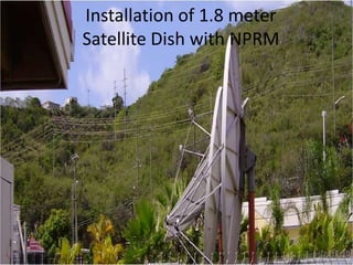
  • 1. Installation of 1.8 meter Satellite Dish with NPRM
  • 2. Location of the 1.8 m Satellite Dish Some important things to take into account when placing you satellite Dish. Location of POE (Point of Entry) Location of steel beams Location for the Satellite Receiver
  • 4. Location of Steel beams This photo indicates the location of the post and steel beams close to the POE. The POE is within 6 feet of this Post which will give great support for this 1.8 meter Satellite Dish.
  • 5. Location of Satellite Receiver Server Room and Satellite Receiver Room. This picture indicates location of power outlets for the equipment.
  • 6. Location of Satellite Receiver This picture shows the beam structure above for running in the Dual Coax cable from the satellite dish. It also shows the direction the cable will run towards the satellite dish.
  • 7. Location of Satellite Receiver This pictures shows the direction the cable will be run to the satellite dish.
  • 8. Building the 1.8 m Satellite Dish Layout your materials so it is easy to find the parts. Layout your you parts to form your non penetrating mount (NPRM). Lay down your rubber mats under your NPRM. Tighten all your bolts. Place your concrete blocks within your NPRM.
  • 9. Building the 1.8 m Satellite Dish Lay out of boxes of materials.
  • 10. Building the 1.8 m Satellite Dish Layout your parts to the NPRM, install rubber mats, and tighten the bolts.
  • 11. Building the 1.8 m Satellite Dish Insert the concrete blocks into the NPRM for support for holding down the satellite dish. This mount should have been 8 blocks each side.
  • 12. Installation of Satellite Dish Lay 1.8 m satellite dish face down install the mounting bracket. Install the post mount on the mast of the NPRM. Install the dish to the post mount. install the horizontal and vertical adjustments for the dish. Install the support arms to the dish and support arm for the ODU.
  • 13. Installation of Satellite Dish Install the ODU on the support arm. Tighten all the bolts to the supports arms and support arm for the ODU.
  • 14. Installation of Satellite Dish Bracket for mounting the satellite dish to the pole mount.
  • 15. Installation of Satellite Dish Bolt for mounting dish to Pole mount.
  • 16. Installation of Satellite Dish Vertical adjustment Horizontal adjustment Pole Mount
  • 17. Installation of Satellite Dish Support Arms
  • 18. Installation of Satellite Dish Installation of the ODU on the support arm.
  • 19. Installation of the Dual RG-6 Cable Install cable up as high as possible – q-deck. Service loops at POE, satellite dish and direct indoor unit (DIU). Cable tied neat with UV tie wraps outside and tie wraps inside. Seal RG-6 Connectors on the ODU with rubber tape then wrapped with black tape. Tag RX with red tape and TX with blue tape.
  • 20. Installation of Dual RG-6 Cable Service loop at POE
  • 21. Installation of Dual RG-6 Cable Service loop at Satellite Dish Service Loop in the Server room for the DIU.
  • 22. Installation of Dual RG-6 Cable Sealed connectors on the RX and TX, also the tagging of red and blue tap.
  • 23. Installation of Dual RG-6 Cable Installation of DIU and the red and blue tape tagging on the RG-6 Cable.
  • 24. Last Items Set the polarization on the ODU. Peak antenna for the satellite required for your service. Peak and pull with the Network Operations Centre (NOC) for Max Cross pole. Complete the certification of DIU with service providers servers.