SlideShare uma empresa Scribd logo
1 de 2
Baixar para ler offline
Scene Capable Plug-In Appliance Module
Cat. No. VRP15
Incandescent: 1800W Fluorescent: 1800VA
Resistive: 15A Motor: 1/2HP
Rated: 120VAC, 60Hz
Installation Instructions
DI-000-VRP15-02A
INTRODUCTION
Leviton’s ViziaRF +TM
components are
designed to communicate with each other
via Radio Frequency (RF) to provide remote
control of your lighting. Using RF technology
allows Leviton to provide the greatest signal
integrity possible. Each module in Leviton’s
Vizia RF +TM
component line is a Z-Wave®
enabled device. In a Z-Wave®
network, each
device is designed to act as a router. These
routers will re-transmit the RF signal from one
device to another until the intended device
is reached. This ensures that the signal is
received by its intended device by routing the
signal around obstacles and radio dead spots.
The Scene Capable Plug-in Appliance Module
is compatible with any Z-Wave®
enabled
network, regardless of the manufacturer and
can also be used with other devices displaying
the Z-Wave®
logo.
CAUTION:
Remember to exercise good common sense
when using the Timer features of your remote,
especially when scheduling unattended
devices. There can be some unexpected
consequences if not used with care. For
example, an empty coffee pot can be remotely
turned on. If that should happen, your coffee
pot could be damaged from overheating. If an
electric heater is turned on by remote control
while clothing is draped over it, a fire could
result. DO NOT USE the remote for the control
of high power heating appliances such as
portable heaters. This device will not control
lighting that is used with electronic low-voltage
and high frequency power supply transformers,
nor high pressure discharge lamps (HID
lighting). This includes mercury-vapor, sodium
vapor and metal halide lamps. DO NOT
change location after unit is enrolled in Z-wave®
network.
NOTES:
•	 If using a non-Leviton Programmer/Remote,
refer to the Programmer/Remote instruction
sheet for including a device.
•	 If using VRCPG install checklist go directly to
step B.
A)	If using a Leviton Z-Wave®
Programmer/
Remote, Cat. No. VRCPG, press the Menu
button and scroll down to System Setup. Press
the center button to select System Setup
Menu. Choose Advance Settings. Press the
center button to select Network.
Including Scene Capable
Plug-In Appliance Module
into Z-Wave®
Network:
Step 3
Attaching Scene Capable
Plug-In Appliance Module to
Wall Receptacle:
Step 2
•	 Plug the Scene Capable Plug-in Appliance
Module into wall receptacle. Verify that
receptacle is live. If controlled by a wall switch,
the switch must be kept ON at all times.
Attaching Load to Scene
Capable Plug-In Appliance
Module:
Step 1
NOTE: In order to use your Vizia RF +TM
Scene
Capable Plug-In Appliance Module in a Z-Wave®
network, it must be included in the network using
a Primary Programmer/Remote, such as Leviton’s
Cat. No. VRCPG. Before including your module,
please refer to the Primary Programmer/Remote
instruction sheet for complete information. Refer
to Step 3 for further details.
•	 Locate load to be controlled by Scene Capable
Plug-In Appliance Module and ensure it is
fully operational. Attach load plug into module
receptacle noting proper polarity of blades.
NOTE: Use check boxes when Steps are
completed.
INSTALLING YOUR APPLIANCE MODULE
B)	While standing close to the module
(approximately 2-5 ft.), press the center
button to <Include> device in the network.
	 NOTE: Only one device may be included
at a time. DO NOT put multiple devices into
the Inclusion mode at any time.
C)	While the Programmer/Remote is in the
Inclusion mode and the LED is ON on
the Scene Capable Plug-In Appliance
Module, press the ON/OFF button on the
module. The Programmer/Remote will verify
inclusion and the LED will turn OFF on the
Scene Capable Plug-In Appliance Module.
	 If the Scene Capable Plug-In Appliance
Module is flashing Amber while in the
Inclusion mode, the Programmer/Remote is
still trying to communicate with the Scene
Capable Plug-In Appliance Module. Wait
until the device stops flashing, then press
ON/OFF button.
	 NOTE: If the LED on the Scene Capable
Plug-In Appliance Module turns solid
Red while including, there has been
a communication error. Refer to
Troubleshooting section.
D)	The Primary Programmer/Remote will
assign a node ID number (Name) for this
module.
	 NOTE: This ID number (Name) will be
stored in the controller to be used for future
reference.
	 NOTE: You may name or edit the node of
this device at this time.
E)	The module is now installed in the
network.
Note: If the module has been successfully
included in the network and the user tries to
include it again without first excluding it from
the network, the module
will retain the first node ID
it had received and ignore
the second.• 	 Switch ON/OFF
• 	 Scene capable
• 	 ON/OFF LED
• 	 Two way communication
• 	 RF reliability
• 	 Ease of installation – No new wiring
• 	 Compatible with other Z-Wave®
enabled
devices
FEATURES
Step 2 cont’d Step 3 cont’d
Programming and
ON/OFF Button
1 ON
2 ON
3 ON
4 ON
OFF
OFF
OFF
OFF
Programmer/Remote
Cat. No. VRCPG
Center Button
Menu Button
WARNINGS AND CAUTIONS:
•	 To be installed and/or used in accordance with appropriate electrical codes and regulations.
•	 If you are unsure about any part of these instructions, consult a qualified electrician.
WARNINGS AND CAUTIONS:
•	 Unplug unit when servicing fixture or changing bulbs.
•	 Save this instruction sheet. It contains important technical data along with testing and
troubleshooting information which will be useful after installation is complete.
LIMITED 5 YEAR WARRANTY AND EXCLUSIONS
Leviton warrants to the original consumer purchaser and not for the benefit of anyone else that this product at the time of its sale by Leviton is free of defects in materials and workmanship under normal and proper use for five years from the
purchase date. Leviton’s only obligation is to correct such defects by repair or replacement, at its option, if within such five year period the product is returned prepaid, with proof of purchase date, and a description of the problem to Leviton
Manufacturing Co., Inc., Att: Quality Assurance Department, 59-25 Little Neck Parkway, Little Neck, New York 11362-2591. This warranty excludes and there is disclaimed liability for labor for removal of this product or reinstallation.
This warranty is void if this product is installed improperly or in an improper environment, overloaded, misused, opened, abused, or altered in any manner, or is not used under normal operating conditions or not in accordance with any
labels or instructions. There are no other or implied warranties of any kind, including merchantability and fitness for a particular purpose, but if any implied warranty is required by the applicable jurisdiction, the duration of any such
implied warranty, including merchantability and fitness for a particular purpose, is limited to five years. Leviton is not liable for incidental, indirect, special, or consequential damages, including without limitation, damage to, or
loss of use of, any equipment, lost sales or profits or delay or failure to perform this warranty obligation. The remedies provided herein are the exclusive remedies under this warranty, whether based on contract, tort or otherwise.
OPERATION
TROUBLESHOOTING
DI-000-VRP15-02A
NOTE: It is very important to accurately exclude
devices from the network when moving or
removing a device from a Z-Wave®
network. This
ensures that all information has been removed
from your Primary
Programmer/Remote’s information table and is
not counted on to be a part of the mesh network.
A)	If using a Leviton Z-Wave®
Programmer/Remote, Cat. No. VRCPG,
press the Menu button and scroll down to
System Setup. Press the center button to
select System Setup Menu. Choose Advance
Settings. Press the center button to select
Network.
B) While standing close to the module, press the
center button to <Exclude> device from the
network.
	 NOTE: Only one device may be excluded at
a time.
C) While the Programmer/Remote is in the
Exclusion mode and the LED is ON on the
Scene Capable Plug-In Appliance Module,
press the ON/OFF button on the module. The
Programmer/Remote will verify Exclusion and
the LED will turn OFF on the Scene Capable
Plug-In Appliance Module.
	 If the Scene Capable Plug-In Appliance
Module is flashing Amber while in the
Exclusion mode, the Programmer/Remote is
still trying to communicate with the module.
Wait until the device stops flashing, then
press the ON/OFF button.
Excluding Scene Capable
Plug-In Appliance Module
from Network:
Step 4
This equipment has been tested and found
to comply with the limits for a Class B Digital
Device, pursuant to Part 15 of the FCC
Rules. These limits are designed to provide
reasonable protection against harmful
interference in a residential installation.
This equipment generates, uses, and can
radiate radio frequency energy and, if not
installed and used in accordance with the
instructions, may cause harmful interference
to radio communications. However, there is
no guarantee that interference will not occur
in a particular installation. If this equipment
does cause harmful interference to radio or
television reception, which can be determined
by turning the equipment OFF and ON,
the user is encouraged to try to correct the
interference by one or more of the following
measures:
•	 Reorient or relocate the receiving Antenna.
•	 Increase the separation between the
equipment and the receiver.
•	 Connect the equipment into an outlet on
a circuit different from that to which the
receiver is connected.
•	 Consult the dealer or an experienced
radio/tv technician for help.
FCC COMPLIANCE STATEMENT
Factory Default:
If your module is not responding, or you are
unable to control it after you have tried to
Include/Exclude it multiple times, it may be
necessary to reset the module to its original
factory settings. To accomplish this, proceed as
follows:
•	 Unplug the module and wait 5 seconds. Plug
the module back in and within 20 seconds
press and hold the programming button until
the LED turns Amber and then flashes Red.
The module is now reset. Once the module is
reset, it will be necessary to Re-Include it to a
network before it can be used.
CAUTION: SETTING A DEVICE TO A
FACTORY DEFAULT DOES NOT EXCLUDE
THAT DEVICE FROM A NETWORK. THE
EXCLUSION PROCEDURE MUST BE
FOLLOWED TO REMOVE THE DEVICE FROM
THE PRIMARY REMOTE’S INFORMATION
TABLE. FAILURE TO DO SO MAY RESULT IN
SYSTEM THAT IS SLOW TO RESPOND, OR
MAY FAIL TO RESPOND TO SOME DEVICES.
Step 3 cont’d Step 4 cont’d
Press ON/OFF Button
Wall
Receptacle
Load plug
Scene Capable Plug-In
Appliance Module
NOTE: Remote must be in close proximity to
Scene Capable Plug-In Appliance Module when
including in the network.
VRCPG
Programmer/Remote
NOTE: For complete details on operating the
Primary Programmer/Remote, refer to the
individual device’s instruction sheet.
ON:	Press the ON/OFF button on the Scene
Capable Plug-In Appliance Module or
appropriate addressed “ON” button on the
applicable controller. The Load will turn
ON.
OFF:	Press the button on the Scene Capable
Plug-In Appliance Module or appropriate
addressed “OFF” button on the applicable
controller. The Load will turn OFF.
If the Scene Capable Plug-In Appliance Module
appears to be functioning improperly, proceed
with the following steps:
1.	 Confirm that the device is being supplied from
a 120V, 60Hz AC source ONLY.
2.	 Confirm that the Load being controlled is in
proper working order. Local switch, ON (check
for burned-out bulbs).
3.	 Confirm that the Load being controlled does
not exceed the module limit.
4.	 Confirm that unit is programmed properly.
Repeat “TO INSTALL” section to verify that it
has been included in the Z-Wave®
network.
MANUAL OPERATION OUT OF NETWORK:
The Scene Capable Plug-in Appliance Module
can control the Load before being included in
the Z-Wave®
network. After powering up the
Scene Capable Plug-In Appliance Module, wait
20 seconds then use ON/OFF button to turn the
Load ON or OFF.
NOTE: If a power interruption should occur while
the module in ON, the light load will return to its
previous state when power is restored.
For additional information, contact Leviton’s
Techline at 1-800-824-3005 or visit Leviton’s
website at www.ViziaRF+.com
Protected under U.S. Patent Number 6,388,399
and patents pending and licensed under
U.S. Patents Numbers 5,905,442, and 5,982,103
Including Scene
Capable Plug-In
Appliance Module
into Z-Wave®
Network:

Mais conteúdo relacionado

Mais procurados

Door lock without handle vision operational manual
Door lock without handle vision operational manualDoor lock without handle vision operational manual
Door lock without handle vision operational manualDomotica daVinci
 
Lightberry User Manual english
Lightberry User Manual englishLightberry User Manual english
Lightberry User Manual englishDomotica daVinci
 
Zipato zd2102 door and window sensor manual english
Zipato zd2102 door and window sensor  manual englishZipato zd2102 door and window sensor  manual english
Zipato zd2102 door and window sensor manual englishDomotica daVinci
 
Fibaro Flood Sensor Manual
Fibaro Flood Sensor Manual Fibaro Flood Sensor Manual
Fibaro Flood Sensor Manual Domotica daVinci
 
Manual sen.inun. vis zf5201
Manual sen.inun. vis zf5201Manual sen.inun. vis zf5201
Manual sen.inun. vis zf5201Domotica daVinci
 
Manual Motor valve pop e009501
Manual Motor valve pop  e009501Manual Motor valve pop  e009501
Manual Motor valve pop e009501Domotica daVinci
 
Configurando Tp-link W8951nd em router
Configurando Tp-link W8951nd em routerConfigurando Tp-link W8951nd em router
Configurando Tp-link W8951nd em routermaxytetsu
 
Manual do modem tp link td-w8960n
Manual do modem tp link td-w8960nManual do modem tp link td-w8960n
Manual do modem tp link td-w8960nmaxytetsu
 
Ph psr03-zipato-z-wave-remote-user-manual
Ph psr03-zipato-z-wave-remote-user-manualPh psr03-zipato-z-wave-remote-user-manual
Ph psr03-zipato-z-wave-remote-user-manualDomotica daVinci
 
Door window sensor 6 manual
Door window sensor 6 manualDoor window sensor 6 manual
Door window sensor 6 manualDomotica daVinci
 
Tl wr740 n-v4_user_guide_1910010682_vn
Tl wr740 n-v4_user_guide_1910010682_vnTl wr740 n-v4_user_guide_1910010682_vn
Tl wr740 n-v4_user_guide_1910010682_vnVi Tính Hoàng Nam
 
Fibaro FGK 101-107-manual_us
Fibaro FGK 101-107-manual_usFibaro FGK 101-107-manual_us
Fibaro FGK 101-107-manual_usDomotica daVinci
 
Manual Nano Switch Z-Wave Plus with metering- Aeon Labs
Manual Nano Switch Z-Wave Plus with metering- Aeon LabsManual Nano Switch Z-Wave Plus with metering- Aeon Labs
Manual Nano Switch Z-Wave Plus with metering- Aeon LabsDomotica daVinci
 
Jual Miring!! Total Station Focus 6?? Call 087778355373-0856180442
Jual Miring!! Total Station Focus 6?? Call 087778355373-0856180442Jual Miring!! Total Station Focus 6?? Call 087778355373-0856180442
Jual Miring!! Total Station Focus 6?? Call 087778355373-0856180442ALAMSURVEY
 
Panduan pelanggan fast net cable modem motorola sb5101
Panduan pelanggan fast net cable modem motorola sb5101Panduan pelanggan fast net cable modem motorola sb5101
Panduan pelanggan fast net cable modem motorola sb5101Thomas Ra Urus
 
MultiSensor Strips Comfort - Z-Wave Plus- Sensative - Manual
MultiSensor Strips Comfort - Z-Wave Plus- Sensative - ManualMultiSensor Strips Comfort - Z-Wave Plus- Sensative - Manual
MultiSensor Strips Comfort - Z-Wave Plus- Sensative - ManualDomotica daVinci
 
Tl wn725 n user guide TL-WN725N
Tl wn725 n user guide  TL-WN725NTl wn725 n user guide  TL-WN725N
Tl wn725 n user guide TL-WN725Nksealexa
 

Mais procurados (20)

Door lock without handle vision operational manual
Door lock without handle vision operational manualDoor lock without handle vision operational manual
Door lock without handle vision operational manual
 
Lightberry User Manual english
Lightberry User Manual englishLightberry User Manual english
Lightberry User Manual english
 
Zipato zd2102 door and window sensor manual english
Zipato zd2102 door and window sensor  manual englishZipato zd2102 door and window sensor  manual english
Zipato zd2102 door and window sensor manual english
 
Fibaro Flood Sensor Manual
Fibaro Flood Sensor Manual Fibaro Flood Sensor Manual
Fibaro Flood Sensor Manual
 
Manual sen.inun. vis zf5201
Manual sen.inun. vis zf5201Manual sen.inun. vis zf5201
Manual sen.inun. vis zf5201
 
Manual Motor valve pop e009501
Manual Motor valve pop  e009501Manual Motor valve pop  e009501
Manual Motor valve pop e009501
 
Configurando Tp-link W8951nd em router
Configurando Tp-link W8951nd em routerConfigurando Tp-link W8951nd em router
Configurando Tp-link W8951nd em router
 
Manual do modem tp link td-w8960n
Manual do modem tp link td-w8960nManual do modem tp link td-w8960n
Manual do modem tp link td-w8960n
 
Ph psr03-zipato-z-wave-remote-user-manual
Ph psr03-zipato-z-wave-remote-user-manualPh psr03-zipato-z-wave-remote-user-manual
Ph psr03-zipato-z-wave-remote-user-manual
 
Fortrezz s 03-manual_us
Fortrezz s 03-manual_usFortrezz s 03-manual_us
Fortrezz s 03-manual_us
 
Ptv1000 um 14_jan10
Ptv1000 um 14_jan10Ptv1000 um 14_jan10
Ptv1000 um 14_jan10
 
Door window sensor 6 manual
Door window sensor 6 manualDoor window sensor 6 manual
Door window sensor 6 manual
 
Tl wr740 n-v4_user_guide_1910010682_vn
Tl wr740 n-v4_user_guide_1910010682_vnTl wr740 n-v4_user_guide_1910010682_vn
Tl wr740 n-v4_user_guide_1910010682_vn
 
Manual zxt 600
Manual zxt 600Manual zxt 600
Manual zxt 600
 
Fibaro FGK 101-107-manual_us
Fibaro FGK 101-107-manual_usFibaro FGK 101-107-manual_us
Fibaro FGK 101-107-manual_us
 
Manual Nano Switch Z-Wave Plus with metering- Aeon Labs
Manual Nano Switch Z-Wave Plus with metering- Aeon LabsManual Nano Switch Z-Wave Plus with metering- Aeon Labs
Manual Nano Switch Z-Wave Plus with metering- Aeon Labs
 
Jual Miring!! Total Station Focus 6?? Call 087778355373-0856180442
Jual Miring!! Total Station Focus 6?? Call 087778355373-0856180442Jual Miring!! Total Station Focus 6?? Call 087778355373-0856180442
Jual Miring!! Total Station Focus 6?? Call 087778355373-0856180442
 
Panduan pelanggan fast net cable modem motorola sb5101
Panduan pelanggan fast net cable modem motorola sb5101Panduan pelanggan fast net cable modem motorola sb5101
Panduan pelanggan fast net cable modem motorola sb5101
 
MultiSensor Strips Comfort - Z-Wave Plus- Sensative - Manual
MultiSensor Strips Comfort - Z-Wave Plus- Sensative - ManualMultiSensor Strips Comfort - Z-Wave Plus- Sensative - Manual
MultiSensor Strips Comfort - Z-Wave Plus- Sensative - Manual
 
Tl wn725 n user guide TL-WN725N
Tl wn725 n user guide  TL-WN725NTl wn725 n user guide  TL-WN725N
Tl wn725 n user guide TL-WN725N
 

Semelhante a Leviton vrp15 z Installation Instructions and Setup Guide

Aeon labs zw130 wall mote quad instructions
Aeon labs zw130 wall mote quad instructionsAeon labs zw130 wall mote quad instructions
Aeon labs zw130 wall mote quad instructionsDomotica daVinci
 
Indoor_Cam_2K_Pan&Tilt_manual_us.pdf
Indoor_Cam_2K_Pan&Tilt_manual_us.pdfIndoor_Cam_2K_Pan&Tilt_manual_us.pdf
Indoor_Cam_2K_Pan&Tilt_manual_us.pdfpsyberdude1
 
Datavideo SE-800
Datavideo SE-800Datavideo SE-800
Datavideo SE-800AV ProfShop
 
Manual aeon labs heavy duty smart switch gen5
Manual   aeon labs heavy duty smart switch gen5Manual   aeon labs heavy duty smart switch gen5
Manual aeon labs heavy duty smart switch gen5Domotica daVinci
 
Vision ZG8101 Wireless Garage Door Detector - Installation Manual
Vision ZG8101 Wireless Garage Door Detector - Installation ManualVision ZG8101 Wireless Garage Door Detector - Installation Manual
Vision ZG8101 Wireless Garage Door Detector - Installation ManualDomotica daVinci
 
Instructions aeon labs door window sensor gen5
Instructions   aeon labs door window sensor gen5Instructions   aeon labs door window sensor gen5
Instructions aeon labs door window sensor gen5Domotica daVinci
 
Z-stick USB wave plus - aeon - manual
Z-stick USB wave plus - aeon - manualZ-stick USB wave plus - aeon - manual
Z-stick USB wave plus - aeon - manualDomotica daVinci
 
Eb1304 Net Sata&Sata+ Manual En
Eb1304 Net Sata&Sata+ Manual  EnEb1304 Net Sata&Sata+ Manual  En
Eb1304 Net Sata&Sata+ Manual Enguest19c905e
 
Leak water Flood Sensro Popp 700052 Manual
Leak water  Flood Sensro Popp 700052 ManualLeak water  Flood Sensro Popp 700052 Manual
Leak water Flood Sensro Popp 700052 ManualDomotica daVinci
 
Manual Smoke Sensor 10 years autonomy - Popp
 Manual Smoke Sensor 10 years autonomy - Popp Manual Smoke Sensor 10 years autonomy - Popp
Manual Smoke Sensor 10 years autonomy - PoppDomotica daVinci
 
Manual 10 year smoke detector Z-Wave Plus-Popp
Manual 10 year smoke detector Z-Wave Plus-PoppManual 10 year smoke detector Z-Wave Plus-Popp
Manual 10 year smoke detector Z-Wave Plus-PoppDomotica daVinci
 
Manual neocoolcam door sensor
Manual neocoolcam door sensorManual neocoolcam door sensor
Manual neocoolcam door sensorDomotica daVinci
 
Door sensor multisensor 4_ in_1 Zipato Z-Wave Plus
Door sensor  multisensor 4_ in_1 Zipato Z-Wave PlusDoor sensor  multisensor 4_ in_1 Zipato Z-Wave Plus
Door sensor multisensor 4_ in_1 Zipato Z-Wave PlusDomotica daVinci
 

Semelhante a Leviton vrp15 z Installation Instructions and Setup Guide (20)

Aeon labs zw130 wall mote quad instructions
Aeon labs zw130 wall mote quad instructionsAeon labs zw130 wall mote quad instructions
Aeon labs zw130 wall mote quad instructions
 
Indoor_Cam_2K_Pan&Tilt_manual_us.pdf
Indoor_Cam_2K_Pan&Tilt_manual_us.pdfIndoor_Cam_2K_Pan&Tilt_manual_us.pdf
Indoor_Cam_2K_Pan&Tilt_manual_us.pdf
 
Manual aeo zw075 zweu
Manual aeo zw075 zweuManual aeo zw075 zweu
Manual aeo zw075 zweu
 
Datavideo SE-800
Datavideo SE-800Datavideo SE-800
Datavideo SE-800
 
Manual aeon labs heavy duty smart switch gen5
Manual   aeon labs heavy duty smart switch gen5Manual   aeon labs heavy duty smart switch gen5
Manual aeon labs heavy duty smart switch gen5
 
Vision ZG8101 Wireless Garage Door Detector - Installation Manual
Vision ZG8101 Wireless Garage Door Detector - Installation ManualVision ZG8101 Wireless Garage Door Detector - Installation Manual
Vision ZG8101 Wireless Garage Door Detector - Installation Manual
 
User guide home_series
User guide home_seriesUser guide home_series
User guide home_series
 
Instructions aeon labs door window sensor gen5
Instructions   aeon labs door window sensor gen5Instructions   aeon labs door window sensor gen5
Instructions aeon labs door window sensor gen5
 
Z-stick USB wave plus - aeon - manual
Z-stick USB wave plus - aeon - manualZ-stick USB wave plus - aeon - manual
Z-stick USB wave plus - aeon - manual
 
Eb1304 Net Sata&Sata+ Manual En
Eb1304 Net Sata&Sata+ Manual  EnEb1304 Net Sata&Sata+ Manual  En
Eb1304 Net Sata&Sata+ Manual En
 
mbot.pdf
mbot.pdfmbot.pdf
mbot.pdf
 
Leak water Flood Sensro Popp 700052 Manual
Leak water  Flood Sensro Popp 700052 ManualLeak water  Flood Sensro Popp 700052 Manual
Leak water Flood Sensro Popp 700052 Manual
 
manual dimmer - Zipato
manual dimmer - Zipatomanual dimmer - Zipato
manual dimmer - Zipato
 
Manual Smoke Sensor 10 years autonomy - Popp
 Manual Smoke Sensor 10 years autonomy - Popp Manual Smoke Sensor 10 years autonomy - Popp
Manual Smoke Sensor 10 years autonomy - Popp
 
Manual 10 year smoke detector Z-Wave Plus-Popp
Manual 10 year smoke detector Z-Wave Plus-PoppManual 10 year smoke detector Z-Wave Plus-Popp
Manual 10 year smoke detector Z-Wave Plus-Popp
 
Manual neocoolcam door sensor
Manual neocoolcam door sensorManual neocoolcam door sensor
Manual neocoolcam door sensor
 
Door sensor multisensor 4_ in_1 Zipato Z-Wave Plus
Door sensor  multisensor 4_ in_1 Zipato Z-Wave PlusDoor sensor  multisensor 4_ in_1 Zipato Z-Wave Plus
Door sensor multisensor 4_ in_1 Zipato Z-Wave Plus
 
H ap qg
H ap qgH ap qg
H ap qg
 
Smart switch 6 manual
Smart switch 6 manualSmart switch 6 manual
Smart switch 6 manual
 
Hcd5 mih
Hcd5 mihHcd5 mih
Hcd5 mih
 

Mais de Alarm Grid

Vizia rf + system programming and control
Vizia rf + system programming and controlVizia rf + system programming and control
Vizia rf + system programming and controlAlarm Grid
 
Vizia rf + plug in spec sheet
Vizia rf + plug in spec sheetVizia rf + plug in spec sheet
Vizia rf + plug in spec sheetAlarm Grid
 
Leviton vrs15 1 lz installation manual and setup guide
Leviton vrs15 1 lz installation manual and setup guideLeviton vrs15 1 lz installation manual and setup guide
Leviton vrs15 1 lz installation manual and setup guideAlarm Grid
 
Leviton vrs05 1 lz installation manual and setup guide
Leviton vrs05 1 lz installation manual and setup guideLeviton vrs05 1 lz installation manual and setup guide
Leviton vrs05 1 lz installation manual and setup guideAlarm Grid
 
Leviton vrr15 1 lz product specification bulletin
Leviton vrr15 1 lz product specification bulletinLeviton vrr15 1 lz product specification bulletin
Leviton vrr15 1 lz product specification bulletinAlarm Grid
 
Leviton vrp03 z product manual and setup guide
Leviton vrp03 z product manual and setup guideLeviton vrp03 z product manual and setup guide
Leviton vrp03 z product manual and setup guideAlarm Grid
 
Leviton vri10 1 lz product manual and setup guide
Leviton vri10 1 lz product manual and setup guideLeviton vri10 1 lz product manual and setup guide
Leviton vri10 1 lz product manual and setup guideAlarm Grid
 
Leviton vri06 1 lz product manual and setup guide
Leviton vri06 1 lz product manual and setup guideLeviton vri06 1 lz product manual and setup guide
Leviton vri06 1 lz product manual and setup guideAlarm Grid
 
Leviton vrf01 1 lz product manual and setup guide
Leviton vrf01 1 lz product manual and setup guideLeviton vrf01 1 lz product manual and setup guide
Leviton vrf01 1 lz product manual and setup guideAlarm Grid
 
Leviton vre06 1 lz
Leviton vre06 1 lzLeviton vre06 1 lz
Leviton vre06 1 lzAlarm Grid
 
Leviton vrcz4 mr, vrcs4-mr, and vrc52-mr product specifications
Leviton vrcz4 mr, vrcs4-mr, and vrc52-mr product specificationsLeviton vrcz4 mr, vrcs4-mr, and vrc52-mr product specifications
Leviton vrcz4 mr, vrcs4-mr, and vrc52-mr product specificationsAlarm Grid
 
Leviton vrcz4 1 l, vrcs4-1l, vrcz1-1l, vrcs1-1l and vrmr1-osg product specifi...
Leviton vrcz4 1 l, vrcs4-1l, vrcz1-1l, vrcs1-1l and vrmr1-osg product specifi...Leviton vrcz4 1 l, vrcs4-1l, vrcz1-1l, vrcs1-1l and vrmr1-osg product specifi...
Leviton vrcz4 1 l, vrcs4-1l, vrcz1-1l, vrcs1-1l and vrmr1-osg product specifi...Alarm Grid
 
Leviton vp00 r 10z, vp00r-1lz, vp0sr-10z, vp0sr-1lz installation manual and s...
Leviton vp00 r 10z, vp00r-1lz, vp0sr-10z, vp0sr-1lz installation manual and s...Leviton vp00 r 10z, vp00r-1lz, vp0sr-10z, vp0sr-1lz installation manual and s...
Leviton vp00 r 10z, vp00r-1lz, vp0sr-10z, vp0sr-1lz installation manual and s...Alarm Grid
 
Leviton dimmers, switches and fan speed controllers
Leviton dimmers, switches and fan speed controllersLeviton dimmers, switches and fan speed controllers
Leviton dimmers, switches and fan speed controllersAlarm Grid
 
Fluorescent dimmer for hi lume or eco-10 ballasts
Fluorescent dimmer for hi lume or eco-10 ballastsFluorescent dimmer for hi lume or eco-10 ballasts
Fluorescent dimmer for hi lume or eco-10 ballastsAlarm Grid
 
Controlling z wave door locks with the vrc0 p
Controlling z wave door locks with the vrc0 pControlling z wave door locks with the vrc0 p
Controlling z wave door locks with the vrc0 pAlarm Grid
 
Vizia rf+ collection
Vizia rf+ collectionVizia rf+ collection
Vizia rf+ collectionAlarm Grid
 
Honeywell vista-50p-user-guide
Honeywell vista-50p-user-guideHoneywell vista-50p-user-guide
Honeywell vista-50p-user-guideAlarm Grid
 
Honeywell vista-50p-install-guide
Honeywell vista-50p-install-guideHoneywell vista-50p-install-guide
Honeywell vista-50p-install-guideAlarm Grid
 
Honeywell vista-50p-connections-summary
Honeywell vista-50p-connections-summaryHoneywell vista-50p-connections-summary
Honeywell vista-50p-connections-summaryAlarm Grid
 

Mais de Alarm Grid (20)

Vizia rf + system programming and control
Vizia rf + system programming and controlVizia rf + system programming and control
Vizia rf + system programming and control
 
Vizia rf + plug in spec sheet
Vizia rf + plug in spec sheetVizia rf + plug in spec sheet
Vizia rf + plug in spec sheet
 
Leviton vrs15 1 lz installation manual and setup guide
Leviton vrs15 1 lz installation manual and setup guideLeviton vrs15 1 lz installation manual and setup guide
Leviton vrs15 1 lz installation manual and setup guide
 
Leviton vrs05 1 lz installation manual and setup guide
Leviton vrs05 1 lz installation manual and setup guideLeviton vrs05 1 lz installation manual and setup guide
Leviton vrs05 1 lz installation manual and setup guide
 
Leviton vrr15 1 lz product specification bulletin
Leviton vrr15 1 lz product specification bulletinLeviton vrr15 1 lz product specification bulletin
Leviton vrr15 1 lz product specification bulletin
 
Leviton vrp03 z product manual and setup guide
Leviton vrp03 z product manual and setup guideLeviton vrp03 z product manual and setup guide
Leviton vrp03 z product manual and setup guide
 
Leviton vri10 1 lz product manual and setup guide
Leviton vri10 1 lz product manual and setup guideLeviton vri10 1 lz product manual and setup guide
Leviton vri10 1 lz product manual and setup guide
 
Leviton vri06 1 lz product manual and setup guide
Leviton vri06 1 lz product manual and setup guideLeviton vri06 1 lz product manual and setup guide
Leviton vri06 1 lz product manual and setup guide
 
Leviton vrf01 1 lz product manual and setup guide
Leviton vrf01 1 lz product manual and setup guideLeviton vrf01 1 lz product manual and setup guide
Leviton vrf01 1 lz product manual and setup guide
 
Leviton vre06 1 lz
Leviton vre06 1 lzLeviton vre06 1 lz
Leviton vre06 1 lz
 
Leviton vrcz4 mr, vrcs4-mr, and vrc52-mr product specifications
Leviton vrcz4 mr, vrcs4-mr, and vrc52-mr product specificationsLeviton vrcz4 mr, vrcs4-mr, and vrc52-mr product specifications
Leviton vrcz4 mr, vrcs4-mr, and vrc52-mr product specifications
 
Leviton vrcz4 1 l, vrcs4-1l, vrcz1-1l, vrcs1-1l and vrmr1-osg product specifi...
Leviton vrcz4 1 l, vrcs4-1l, vrcz1-1l, vrcs1-1l and vrmr1-osg product specifi...Leviton vrcz4 1 l, vrcs4-1l, vrcz1-1l, vrcs1-1l and vrmr1-osg product specifi...
Leviton vrcz4 1 l, vrcs4-1l, vrcz1-1l, vrcs1-1l and vrmr1-osg product specifi...
 
Leviton vp00 r 10z, vp00r-1lz, vp0sr-10z, vp0sr-1lz installation manual and s...
Leviton vp00 r 10z, vp00r-1lz, vp0sr-10z, vp0sr-1lz installation manual and s...Leviton vp00 r 10z, vp00r-1lz, vp0sr-10z, vp0sr-1lz installation manual and s...
Leviton vp00 r 10z, vp00r-1lz, vp0sr-10z, vp0sr-1lz installation manual and s...
 
Leviton dimmers, switches and fan speed controllers
Leviton dimmers, switches and fan speed controllersLeviton dimmers, switches and fan speed controllers
Leviton dimmers, switches and fan speed controllers
 
Fluorescent dimmer for hi lume or eco-10 ballasts
Fluorescent dimmer for hi lume or eco-10 ballastsFluorescent dimmer for hi lume or eco-10 ballasts
Fluorescent dimmer for hi lume or eco-10 ballasts
 
Controlling z wave door locks with the vrc0 p
Controlling z wave door locks with the vrc0 pControlling z wave door locks with the vrc0 p
Controlling z wave door locks with the vrc0 p
 
Vizia rf+ collection
Vizia rf+ collectionVizia rf+ collection
Vizia rf+ collection
 
Honeywell vista-50p-user-guide
Honeywell vista-50p-user-guideHoneywell vista-50p-user-guide
Honeywell vista-50p-user-guide
 
Honeywell vista-50p-install-guide
Honeywell vista-50p-install-guideHoneywell vista-50p-install-guide
Honeywell vista-50p-install-guide
 
Honeywell vista-50p-connections-summary
Honeywell vista-50p-connections-summaryHoneywell vista-50p-connections-summary
Honeywell vista-50p-connections-summary
 

Leviton vrp15 z Installation Instructions and Setup Guide

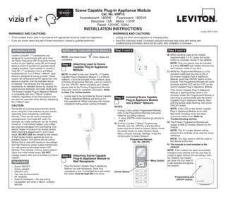
  • 1. Scene Capable Plug-In Appliance Module Cat. No. VRP15 Incandescent: 1800W Fluorescent: 1800VA Resistive: 15A Motor: 1/2HP Rated: 120VAC, 60Hz Installation Instructions DI-000-VRP15-02A INTRODUCTION Leviton’s ViziaRF +TM components are designed to communicate with each other via Radio Frequency (RF) to provide remote control of your lighting. Using RF technology allows Leviton to provide the greatest signal integrity possible. Each module in Leviton’s Vizia RF +TM component line is a Z-Wave® enabled device. In a Z-Wave® network, each device is designed to act as a router. These routers will re-transmit the RF signal from one device to another until the intended device is reached. This ensures that the signal is received by its intended device by routing the signal around obstacles and radio dead spots. The Scene Capable Plug-in Appliance Module is compatible with any Z-Wave® enabled network, regardless of the manufacturer and can also be used with other devices displaying the Z-Wave® logo. CAUTION: Remember to exercise good common sense when using the Timer features of your remote, especially when scheduling unattended devices. There can be some unexpected consequences if not used with care. For example, an empty coffee pot can be remotely turned on. If that should happen, your coffee pot could be damaged from overheating. If an electric heater is turned on by remote control while clothing is draped over it, a fire could result. DO NOT USE the remote for the control of high power heating appliances such as portable heaters. This device will not control lighting that is used with electronic low-voltage and high frequency power supply transformers, nor high pressure discharge lamps (HID lighting). This includes mercury-vapor, sodium vapor and metal halide lamps. DO NOT change location after unit is enrolled in Z-wave® network. NOTES: • If using a non-Leviton Programmer/Remote, refer to the Programmer/Remote instruction sheet for including a device. • If using VRCPG install checklist go directly to step B. A) If using a Leviton Z-Wave® Programmer/ Remote, Cat. No. VRCPG, press the Menu button and scroll down to System Setup. Press the center button to select System Setup Menu. Choose Advance Settings. Press the center button to select Network. Including Scene Capable Plug-In Appliance Module into Z-Wave® Network: Step 3 Attaching Scene Capable Plug-In Appliance Module to Wall Receptacle: Step 2 • Plug the Scene Capable Plug-in Appliance Module into wall receptacle. Verify that receptacle is live. If controlled by a wall switch, the switch must be kept ON at all times. Attaching Load to Scene Capable Plug-In Appliance Module: Step 1 NOTE: In order to use your Vizia RF +TM Scene Capable Plug-In Appliance Module in a Z-Wave® network, it must be included in the network using a Primary Programmer/Remote, such as Leviton’s Cat. No. VRCPG. Before including your module, please refer to the Primary Programmer/Remote instruction sheet for complete information. Refer to Step 3 for further details. • Locate load to be controlled by Scene Capable Plug-In Appliance Module and ensure it is fully operational. Attach load plug into module receptacle noting proper polarity of blades. NOTE: Use check boxes when Steps are completed. INSTALLING YOUR APPLIANCE MODULE B) While standing close to the module (approximately 2-5 ft.), press the center button to <Include> device in the network. NOTE: Only one device may be included at a time. DO NOT put multiple devices into the Inclusion mode at any time. C) While the Programmer/Remote is in the Inclusion mode and the LED is ON on the Scene Capable Plug-In Appliance Module, press the ON/OFF button on the module. The Programmer/Remote will verify inclusion and the LED will turn OFF on the Scene Capable Plug-In Appliance Module. If the Scene Capable Plug-In Appliance Module is flashing Amber while in the Inclusion mode, the Programmer/Remote is still trying to communicate with the Scene Capable Plug-In Appliance Module. Wait until the device stops flashing, then press ON/OFF button. NOTE: If the LED on the Scene Capable Plug-In Appliance Module turns solid Red while including, there has been a communication error. Refer to Troubleshooting section. D) The Primary Programmer/Remote will assign a node ID number (Name) for this module. NOTE: This ID number (Name) will be stored in the controller to be used for future reference. NOTE: You may name or edit the node of this device at this time. E) The module is now installed in the network. Note: If the module has been successfully included in the network and the user tries to include it again without first excluding it from the network, the module will retain the first node ID it had received and ignore the second.• Switch ON/OFF • Scene capable • ON/OFF LED • Two way communication • RF reliability • Ease of installation – No new wiring • Compatible with other Z-Wave® enabled devices FEATURES Step 2 cont’d Step 3 cont’d Programming and ON/OFF Button 1 ON 2 ON 3 ON 4 ON OFF OFF OFF OFF Programmer/Remote Cat. No. VRCPG Center Button Menu Button WARNINGS AND CAUTIONS: • To be installed and/or used in accordance with appropriate electrical codes and regulations. • If you are unsure about any part of these instructions, consult a qualified electrician. WARNINGS AND CAUTIONS: • Unplug unit when servicing fixture or changing bulbs. • Save this instruction sheet. It contains important technical data along with testing and troubleshooting information which will be useful after installation is complete.
  • 2. LIMITED 5 YEAR WARRANTY AND EXCLUSIONS Leviton warrants to the original consumer purchaser and not for the benefit of anyone else that this product at the time of its sale by Leviton is free of defects in materials and workmanship under normal and proper use for five years from the purchase date. Leviton’s only obligation is to correct such defects by repair or replacement, at its option, if within such five year period the product is returned prepaid, with proof of purchase date, and a description of the problem to Leviton Manufacturing Co., Inc., Att: Quality Assurance Department, 59-25 Little Neck Parkway, Little Neck, New York 11362-2591. This warranty excludes and there is disclaimed liability for labor for removal of this product or reinstallation. This warranty is void if this product is installed improperly or in an improper environment, overloaded, misused, opened, abused, or altered in any manner, or is not used under normal operating conditions or not in accordance with any labels or instructions. There are no other or implied warranties of any kind, including merchantability and fitness for a particular purpose, but if any implied warranty is required by the applicable jurisdiction, the duration of any such implied warranty, including merchantability and fitness for a particular purpose, is limited to five years. Leviton is not liable for incidental, indirect, special, or consequential damages, including without limitation, damage to, or loss of use of, any equipment, lost sales or profits or delay or failure to perform this warranty obligation. The remedies provided herein are the exclusive remedies under this warranty, whether based on contract, tort or otherwise. OPERATION TROUBLESHOOTING DI-000-VRP15-02A NOTE: It is very important to accurately exclude devices from the network when moving or removing a device from a Z-Wave® network. This ensures that all information has been removed from your Primary Programmer/Remote’s information table and is not counted on to be a part of the mesh network. A) If using a Leviton Z-Wave® Programmer/Remote, Cat. No. VRCPG, press the Menu button and scroll down to System Setup. Press the center button to select System Setup Menu. Choose Advance Settings. Press the center button to select Network. B) While standing close to the module, press the center button to <Exclude> device from the network. NOTE: Only one device may be excluded at a time. C) While the Programmer/Remote is in the Exclusion mode and the LED is ON on the Scene Capable Plug-In Appliance Module, press the ON/OFF button on the module. The Programmer/Remote will verify Exclusion and the LED will turn OFF on the Scene Capable Plug-In Appliance Module. If the Scene Capable Plug-In Appliance Module is flashing Amber while in the Exclusion mode, the Programmer/Remote is still trying to communicate with the module. Wait until the device stops flashing, then press the ON/OFF button. Excluding Scene Capable Plug-In Appliance Module from Network: Step 4 This equipment has been tested and found to comply with the limits for a Class B Digital Device, pursuant to Part 15 of the FCC Rules. These limits are designed to provide reasonable protection against harmful interference in a residential installation. This equipment generates, uses, and can radiate radio frequency energy and, if not installed and used in accordance with the instructions, may cause harmful interference to radio communications. However, there is no guarantee that interference will not occur in a particular installation. If this equipment does cause harmful interference to radio or television reception, which can be determined by turning the equipment OFF and ON, the user is encouraged to try to correct the interference by one or more of the following measures: • Reorient or relocate the receiving Antenna. • Increase the separation between the equipment and the receiver. • Connect the equipment into an outlet on a circuit different from that to which the receiver is connected. • Consult the dealer or an experienced radio/tv technician for help. FCC COMPLIANCE STATEMENT Factory Default: If your module is not responding, or you are unable to control it after you have tried to Include/Exclude it multiple times, it may be necessary to reset the module to its original factory settings. To accomplish this, proceed as follows: • Unplug the module and wait 5 seconds. Plug the module back in and within 20 seconds press and hold the programming button until the LED turns Amber and then flashes Red. The module is now reset. Once the module is reset, it will be necessary to Re-Include it to a network before it can be used. CAUTION: SETTING A DEVICE TO A FACTORY DEFAULT DOES NOT EXCLUDE THAT DEVICE FROM A NETWORK. THE EXCLUSION PROCEDURE MUST BE FOLLOWED TO REMOVE THE DEVICE FROM THE PRIMARY REMOTE’S INFORMATION TABLE. FAILURE TO DO SO MAY RESULT IN SYSTEM THAT IS SLOW TO RESPOND, OR MAY FAIL TO RESPOND TO SOME DEVICES. Step 3 cont’d Step 4 cont’d Press ON/OFF Button Wall Receptacle Load plug Scene Capable Plug-In Appliance Module NOTE: Remote must be in close proximity to Scene Capable Plug-In Appliance Module when including in the network. VRCPG Programmer/Remote NOTE: For complete details on operating the Primary Programmer/Remote, refer to the individual device’s instruction sheet. ON: Press the ON/OFF button on the Scene Capable Plug-In Appliance Module or appropriate addressed “ON” button on the applicable controller. The Load will turn ON. OFF: Press the button on the Scene Capable Plug-In Appliance Module or appropriate addressed “OFF” button on the applicable controller. The Load will turn OFF. If the Scene Capable Plug-In Appliance Module appears to be functioning improperly, proceed with the following steps: 1. Confirm that the device is being supplied from a 120V, 60Hz AC source ONLY. 2. Confirm that the Load being controlled is in proper working order. Local switch, ON (check for burned-out bulbs). 3. Confirm that the Load being controlled does not exceed the module limit. 4. Confirm that unit is programmed properly. Repeat “TO INSTALL” section to verify that it has been included in the Z-Wave® network. MANUAL OPERATION OUT OF NETWORK: The Scene Capable Plug-in Appliance Module can control the Load before being included in the Z-Wave® network. After powering up the Scene Capable Plug-In Appliance Module, wait 20 seconds then use ON/OFF button to turn the Load ON or OFF. NOTE: If a power interruption should occur while the module in ON, the light load will return to its previous state when power is restored. For additional information, contact Leviton’s Techline at 1-800-824-3005 or visit Leviton’s website at www.ViziaRF+.com Protected under U.S. Patent Number 6,388,399 and patents pending and licensed under U.S. Patents Numbers 5,905,442, and 5,982,103 Including Scene Capable Plug-In Appliance Module into Z-Wave® Network: