Bajaj Allianz Life Insurance Company - Insurer Innovation Award 2024
Theme 6
1. SECTION 1. AERODYNAMICS OF LIFTING SURFACES
THEME 6. THE AERODYNAMIC CHARACTERISTICS OF
WINGS IN A SUPERSONIC GAS FLOW.
WING IN TRANSONIC RANGE OF SPEEDS
The wing aerodynamic characteristics in the supersonic gas flow
( 1,20 ...1,25 ≤ M∞ ≤ 4 ...5 ) depend on edges type: subsonic or supersonic. In the
beginning we shall consider the aerodynamic characteristics of wings of the individual
plan forms and on their example we shall reveal some common properties characteristic
for wings of derived plan forms. Then we shall consider features of the aerodynamic
characteristics of wings with various plan forms.
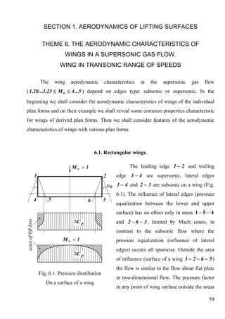
6.1. Rectangular wings.
The leading edge 1 − 2 and trailing
edge 3 − 4 are supersonic, lateral edges
1 − 4 and 2 − 3 are subsonic on a wing (Fig.
6.1). The influence of lateral edges (pressure
equalization between the lower and upper
surface) has an effect only in areas 1 − 5 − 4
and 2 − 6 − 3 , limited by Mach cones, in
contrast to the subsonic flow where the
pressure equalization (influence of lateral
edges) occurs all spanwise. Outside the area
of influence (surface of a wing 1 − 2 − 6 − 5 )
the flow is similar to the flow about flat plate
Fig. 6.1. Pressure distribution
in two-dimensional flow. The pressure factor
On a surface of a wing
in any point of wing surface outside the areas
59
2. of influence of lateral edges is equal
2α
C р up .lo . = C р ∞ = ±2α tgμ 0 = ± . (6.1)
2
M∞ −1
In the field of influence of lateral edges the factor of pressure is determined
2 tgυ
C р up .lo . = C р ∞ arcsin . (6.2)
π tgμ ∞
(Here the wing is considered as a flat plate). The last formula is
recorded for case when there is no mutual influence of the
right-hand and left-hand lateral edges (Fig. 6.2). This influence
appears at such Mach numbers, when the Mach cone of the left-
hand (or the right-hand) lateral edge crosses the right-hand
(left-hand) lateral edge.
Fig. 6.2.
The limit case of mutual influence absence is determined
2
by a condition λ M∞ − 1 < 1 . Fig. 6.3. shows probable cases of lateral edges mutual
influence.
2 2 2 2 2
λ M∞ − 1 < 1 λ M∞ − 1 = 1 λ M∞ − 1 < 2 λ M∞ − 1 = 2 λ M∞ − 1 > 2
Fig. 6.3.
The factor of pressure in the field of mutual influence of lateral edges is
determined by more complex formulae; they are shown in special literature.
Summarizing distributed pressure we shall define the aerodynamic characteristics.
2
The following formulas are received for the case when λ M∞ − 1 ≥ 1 :
C ya = C α ⋅ α ;
ya (6.3)
4 ⎛ 1 ⎞
α ⎜1 − ⎟;
C ya = (6.4)
2 ⎜
M∞ − 1 ⎝ 2 λ M∞ − 1 ⎟
2
⎠
60
3. C xa = C xw + C xi ; (6.5)
Bc
2⎛ 1 ⎞
C xw = ⎜1 − ⎟; (6.6)
2 ⎜
M∞ − 1 ⎝ 2λ M ∞ − 1 ⎟
2
⎠
2
C xi = C ya ⋅ α = AC ya ; (6.7)
2
λ M∞ − 1 − 2 3
x F = 0 .5 . (6.8)
2
λ M∞ −1−1 2
2
At λ M∞ − 1 < 1 equations for the aerodynamic characteristics for rectangular
wings become considerably complicated.
Let's analyze the aerodynamic characteristics.
6.1.1. Lift.
1. The dependence C ya = f ( α ) is linear for any aspect ratio wing ( λ ≥ 3 ).
2. With increasing of λ the value of a derivative C α grows and at λ → ∞ tends
ya
4
to the airfoil characteristic C α → C α ∞ =
ya ya (Fig. 6.4). This tendency takes
2
M∞ −1
place faster than in subsonic flow, that is explained by the limited area of the lateral
edges influence at M∞ > 1 .
3. The value of derivative C α decreases and tends to C α ∞ with increasing of
ya ya
Mach numbers M ∞ , that is connected with narrowing of Mach cones at growth of M ∞
and reduction of lateral edges influence (Fig. 6.5). It is possible to assume, that
Cα ≈ Cα ∞
ya ya already at 2
λ M∞ − 1 ≥ 7 ...8 (difference is less than 7% at
2 2
λ M∞ − 1 = 7 , at λ M∞ − 1 = 10 - less than 5% ).
61
4. Fig. 6.4. Dependence C ya = f ( α ) Fig. 6.5. Dependence C ya = f ( α )
at M ∞ = const at λ = const
Cα
ya
4. The ratio is the universal dependence on the reduced aspect ratio
λ
2
λ M∞ − 1 .
6.1.2. Drag.
There is only pressure drag which determines wave drag and induced drag
C xa = C xw + C xi in the inviscid supersonic flow. As the wing leading edge is
supersonic, then there is no sucking force and C xi = C ya ⋅ α (for flat wing). As
1 1
C ya = C α ⋅ α and α =
ya
2
C ya , then C xi = C ya ⋅ A ; A = α . So influence of λ onto
Cα
ya C ya
C xi at M ∞ > 1 is weaker than in subsonic flow (for example at λ ≥ 4
2
1+δ 2 Bc
C xi = C ya ). The wave drag C xw is defined by airfoil drag C xw ∞ = and
πλ 2
M∞ −1
⎛ 1 ⎞
multiplier ⎜1− ⎟ which is taking into account span finite. Let's notice, that
⎜ 2 λ M∞ − 1 ⎟
2
⎝ ⎠
62
5. in case of unswept wing, the same multiplier is included in the formula for C α (6.4).
ya
As well as C ya , the value of parameter C xw → C xw ∞ with increasing of M ∞ and λ
2
(more precisely λ M∞ − 1 ). It is explained by narrowing of Mach cone and reduction
2
of lateral edges influence. It is possible to consider that at λ M∞ − 1 ≥ 7 ...8
C xw
C xw ≈ C xw∞ (error ≈ 7% ). The ratio is dependent only on reduced aspect ratio
2
λc
and factor of the airfoil plan form B i.e.
C xw
λc 2 ( 2
)
= f λ M ∞ − 1 , airfoil planform .
6.1.3. Location of aerodynamic center.
"Loss" of lift in the wing areas falling inside
the Mach cones will cause displacement of pressure
center and aerodynamic center forward, to the leading
edge, in comparison with location of the airfoil
aerodynamic center x F∞ = 0 .5 (Fig. 6.6). The
location of aerodynamic center is a function of aspect
Fig. 6.6 ratio x F = f ⎛ λ M ∞ − 1 ⎞ .
⎜ 2 ⎟
⎝ ⎠
2 2
At λ M∞ − 1 → ∞ x F → x F∞ . Approximately x F ≈ x F∞ at λ M∞ − 1 ≥ 7
2
with an error less than 3% . At λ M∞ − 1 = 5 x F = 0 .96 ⋅ 0 .5 = 0 .48 difference from
x F∞ is 4% .
63
6. 6.2. Triangular wings with subsonic leading edges.
Let's consider a triangular wing with subsonic
leading edges. With the help of fig. 6.7. we get an
internal sweep angle 90 o − χ l .e . < μ ∞ and
ctgχ l .e . 2 1 2
n= = M ∞ − 1 ctgχ l .e . = λ M∞ − 1 < 1 .
tg μ ∞ 4
Thus triangular wing with subsonic edges has
2
reduced aspect ratio less than 4 ( λ M∞ − 1 < 4 ). In
this case there is an overflow from the lower surface to
Fig. 6.7. A triangular wing the upper surface. The sucking force is realized on the
with subsonic edges leading edge and reduces induced drag. There is also
non-linear additive to the lift coefficient ΔC ya .
Pressure distribution along wing surface (fig. 6.8)
submits to the law within the linear theory ( α << 1 )
2α tgγ l .e .
C р up .l . = ± , .9)
E 1 − t2
tgϑ
where t = and γ l .e . = 90 o − χ l .e . (refer to fig.
tgγ l .e .
6.7); it is possible to define approximately E - the
elliptical integral of II type dependent on
1 2
Fig. 6.8. Pressure distribution parameter n = λ M∞ − 1 , by the formula
4
in wing cross-section
E ≈ ( 1,0 + 0 ,6 n) − n .
2
It follows from the formula (6.9) for C p that on each ray ϑ = const value of
C p = const , that is the feature of conical flows. At ϑ → γ l .e . i.e. at approach to the
leading edge C p → ±∞ (the similar situation takes place in a subsonic flow). For a
sharp edge the site in nose section is equal to zero. Multiplying C p onto the nose
64
7. section area and expanding the uncertainty ∞ ⋅ 0 , we receive final force value which
projection onto incoming flow direction creates force F reducing the induced drag.
This is the sucking force. The aerodynamic characteristics of a triangular wing with
subsonic edges are determined by the following formulae:
C ya = C α ⋅ α + ΔC ya , C xa = C xw + C xi ;
ya (6.10)
4 π ⋅n πλ
Cα =
ya ⋅ = ; (6.11)
2
M∞ −1 2E 2E
4C α
ya
ΔC ya = 1 − M ∞ cos χ l .e . ⋅ α 2 ;
2
(6.12)
πλ
2
Bc
C xв = n (1.1 + 0 .2 n) ; (6.13)
2
M∞ − 1
2 1 1 − n2
C xi = C ya ⋅ α − CF ≈ AC ya ; A= −ξ , (6.14)
α πλ
C ya
where ξ is a factor of realization of sucking force ( ξ theor = 1 ), it is possible to adopt for
sharp leading edges, that ξ ≈ 0 ; for rounded edges - ξ ≈ 0 .8 − 1.2C ya at
0 ≤ C ya ≤ 0 .66 , further ξ ≈ 0 .
xF 2
For a triangular wing x F = = . The last result follows from consideration of
b0 3
conical flow with constant pressure C p = const on rays outgoing from the wing top.
6.2.1. Analysis of the aerodynamic characteristics.
1. At n → 0 , that corresponds to λ → 0 or M ∞ → 1 (or simultaneously) we
πλ
receive C α =
ya . That means, the result corresponds to the extremely low-aspect-ratio
2
wing in incompressible and subsonic gas flows. If the wing leading edge becomes sound
65
8. 4
( n = 1 ), then C α =
ya , i.e. we receive the characteristic of the airfoil of infinite
2
M∞ −1
aspect ratio wing in supersonic gas flow.
2. In case of sound and supersonic edges ( M ∞ cos χ l .e . ≥ 1 ) the non-linear
additive to a lift coefficient is equal to zero, i.e. ΔC ya = 0 .
πλ
3. If n → 0 , then C α →
ya and at ξ theor = 1 a polar pull-off coefficient
2
1 1 2
A= , i.e. wing. induced drag C xi = C ya ; so as for subsonic flow high-aspect-
πλ πλ
2
ratio wing. It is clear that the sucking force CF C ya reduces the induced drag twice in
comparison with that case, if it is not taken into account.
Cα
ya C xw 2
4. Ratios and are also functions of reduced aspect ratio λ M∞ − 1
λ λc
2
C xw
and airfoil plan form (for ).
2
λc
6.3. Triangular wing with supersonic leading edges.
1 2
If the leading edges of a triangular wing are supersonic - n = λ M∞ − 1 > 1 .
4
The overflow is absent and the sucking force is not realized on the leading edge. It is
possible to mark out two characteristic flow areas (Fig. 6.9). The wing areas I (shaded
sites) outside the Mach cone are streamlined as the isolated slipping wing of infinite
span, irrespective of other wing part. The pressure in these areas is constant and
pressure factor is determined:
C p∞
C pI = , (6.15)
2
1−σ
66
9. 2α 1 4
where C p ∞ = ± is the pressure factor on the airfoil; σ = = or
2
M∞ − 1 n λ M2 − 1
∞
tgμ 0
σ= is the leading edge characteristic.
tgγ l .e .
There is an influence of the angular point (wing
top) in the wing central part falling into Mach cone.
Conical flow takes place in this area II, for which the
constancy of pressure on each ray outgoing from wing
top is characteristic, but pressure on different rays is
various. The pressure factor for such case is determined
as
⎛ 2 2⎞
⎜ 1 − 2 arcsin σ − t ⎟ , (6.16)
C p∞
C pII =
⎜ π 1 − t2 ⎟
1−σ2 ⎝ ⎠
Fig. 6.9. Triangular wing
where t = tgϑ tgγ l .e . , 0 ≤ t ≤ σ .
with supersonic edges
The integration of pressure distribution results in
the following formulas for the aerodynamic characteristics:
C ya = C α ⋅ α , C xa = C xw + C xi , C xi = C ya ⋅ α = AC ya ,
ya
2
4
Cα =
ya , (6.17)
2
M∞ − 1
2
Bc ⎛ 0 .3 ⎞
C xw = n⎜1 + ⎟, (6.18)
2
M∞ − 1 ⎝ n2 ⎠
2
1 M∞ − 1
A= = , (6.19)
Cα
ya 4
xF 2
xF = = . (6.20)
b0 3
It is noteworthy, that the value of C α for triangular wing with supersonic leading
ya
edges coincides with the airfoil characteristic C α ∞ (the difference is in pressure
ya
67
10. distribution). The pressure rising at tip sites compensates pressure decreasing in central
area of the triangular wing. It can be shown, that the share of tip sites in total lift comes
n−1
to , that at n = 1.5 corresponds to ≈ 45% and at n = 2 - ≈ 57% .
n+ 1
Cα
ya C xw
Just as for a wing with subsonic edges, the ratios and are also functions
λ λc
2
2
of λ M∞ − 1 and airfoil shape for wave drag (Fig. 6.10, 6.11). It is necessary to note,
that the formulas for a triangular wing with subsonic and supersonic edges are
theoretically joint to a fracture at n = 1 or ⎛ λ M ∞ − 1 =
⎜ 2
4⎞ .
⎟
⎝ ⎠
Experimentally this fracture is smoothed out. In point A the leading edge passes
from a subsonic flow mode to supersonic flow. The application of wings with subsonic
edges is evident on a curve of wave drag (in this case the induced drag decreases too
due to realization of sucking force). The most adverse flow mode is in zone of M ∞
numbers corresponding to a sound leading edge.
Cα
ya Fig. 6.11. Dependence of
C xw
on reduced
Fig. 6.10. Dependence of on reduced 2
λ λc
68
11. 2 2
aspect ratio λ M∞ − 1 aspect ratio λ M∞ − 1
It is interesting to note, that if triangular wing is put into flow by the reverse side
(Fig. 6.12), then pressure distribution along the inverted wing will be the same as for a
2α
wing of infinite aspect ratio, i.e. C p = C p ∞ = ± . In this case lift coefficient
2
M∞ −1
C α and induced drag C xi will be the same, as on the initial triangular wing. It is a
ya
particular case of the general theorem of reversibility. According to this theorem, the
lift of a flat wing of any plan form at the direct and inverted flow will be identical, if the
angles of attack and speeds of undisturbed
flow are identical. For induced drag the
equality will be obeyed at supersonic leading
edges (in direct and inverted flows) or at
identical values of sucking forces.
Considering the load distribution along
Fig. 6.12. wing surface it is possible to make the
conclusion that the cut-out of trailing edge
(form such as “swallow's tail”) (Fig. 6.13,1) should result to the increasing of C α , and
ya
additive of the area to a trailing edge
(Fig. 6.13,3) - to decreasing of C α . It is possible to write down C α 1 > C α 2 > C α 3 .
ya ya ya ya
69
12. Fig. 6.13. Various versions of trailing edge shape
At χ t .e . ≤ 20 o the wings aerodynamic characteristics are determined by the
characteristics of the initial triangular wing by multiplication to a factor dependent on
1 ctgχ l .e .
the ratio of sweep angles on forward and trailing edges , where ε = − .
(1 + ε ) ctgχ t .e .
It is necessary to take the sweep angle on the trailing edge with its own sign. So
derivative of a lift coefficient C α , wave drag and location of aerodynamic center are
ya
defined by the formulae
α CαΔ
y C xw Δ xF Δ
C ya = ; C xw = ; xF = . (6.21)
1+ε 1+ε 1+ε
6.4. Wings of any plan form.
The qualitative analysis of the aerodynamic characteristics.
The main feature of the aerodynamic characteristics of all wings: with increasing
2
of Mach numbers M ∞ (more precisely - reduced aspect ratio λ M∞ − 1 ) the
aerodynamic characteristics C α , C xw tend to the airfoil characteristics, i.e.
ya
2
α α 4 Bc
C ya = C ya ∞ = ; C xw = C xw ∞ = . It can be explained, by the
2 2
M∞ −1 M∞ − 1
fact that the Mach cone is narrowing with increasing of M ∞ (at λ = const ) and
each cross-section of a wing will be also isolated streamlined. It also follows, that
the wing aerodynamic center (or center of pressure) displaces into the center of
mass of the plan form, i.e. x F = x c .g . .
Let's analyze the aerodynamic characteristics of wings.
70
13. 6.4.1. Lift.
Generally for flat wing C ya = C α ⋅ α + ΔC ya , where ΔC ya is the non-linear
ya
additive exists only at a subsonic leading edge. It can be estimated by the formula
4
ΔC ya = C α 1 − M ∞ cos 2 χ l .e . ⋅ α 2
ya
2
πλ
At M ∞ cos χ l .e . ≥ 1 (supersonic edge) ΔC ya = 0 . There are schedules
constructed in a generalized form for definition of the derivative C α , as the
ya
Cα Cα
= f ⎛ λ M ∞ − 1, λ tgχ 0 .5 , η ⎞ .
ya ya 2
dependence on parameters of similarity: ⎜ ⎟
λ λ ⎝ ⎠
Approximately it is possible to consider, that the taper η practically does not
influence the lift coefficient. For each wing the function
Cα
= f ⎛ λ M ∞ − 1, λ tgχ 0 .5 , η ⎞ is various. However, as it was mentioned above, at
ya 2
⎜ ⎟
λ ⎝ ⎠
2 Cα
ya 4
λ M∞ − 1 → ∞ we receive for all wings = . Practically this
λ 2
λ M∞ − 1
2
dependence can be used at λ M∞ − 1 ≥ 6 ...7 .
Cα
ya
The general view of dependence
λ
is shown in a Fig. 6.14. The presence of
fractures at changing of flow modes about
edges is characteristic for it:
In point A - the trailing edge passes
from subsonic to supersonic flow mode;
In point B - the leading edge passes
from subsonic to supersonic flow mode.
In experiment these fractures are
Fig. 6.14.
smoothed out.
71
14. 6.4.2. Wave drag.
C xw
Generally = f ⎛ λ M ∞ − 1 , λ tgχ 0 .5 , η , airfoil shape ⎞ .
⎜ 2 ⎟ At
2 ⎝ ⎠
λc
2
λ M∞ − 1 → ∞ irrespectively of the wing plan form we shall have
C xw B
= as the characteristic of an airfoil. Practically this formula can be
2 2
λс λ M∞ − 1
2
used at λ M∞ − 1 ≥ 6 ...7 . It is necessary to note weak influence of taper onto wave
drag. The presence of fractures on a curve (Fig. 6.15). is characteristic for general
C xw
dependence on the reduced aspect ratio.
2
λc
72
15. The fracture in point A - wing trailing
edge passes from a subsonic flow mode to
supersonic; in point C - transition of the
maximum thickness line from subsonic to
supersonic flow; in a point B - the leading
edge passes from subsonic to supersonic flow
mode. These fractures are not present in
experimental dependencies, they are
smoothed out.
Fig. 6.15. The maximum of curves is observed in
the area of transition of the maximum
thickness line ( χc ) from a subsonic flow
mode to supersonic (point C ). For a sound
line of maximum thickness
2
λ tgχ c = λ M ∞ − 1 . It is necessary to note
that at subsonic lines of maximum thickness
the wave drag of swept wings is less than
drag of unswept wing. Thus the longer wing
aspect ratio (at χc = const ), sweep (at
Fig. 6.16.
λ = const ) or parameter λ tgχ c is, then the
bigger profit is received in drag. On the contrary, at a supersonic line of maximum
thickness the wave drag of swept wing is more than of unswept one (Fig. 6.16).
6.4.3. Induced drag.
2
If the leading edge is supersonic, then C xi = C ya α or C xi = AC ya , where
A = 1 C α - for the flat wing. At the subsonic leading edge it is necessary to take into
ya
account the sucking force. In this case C xi = C ya α − CF , or approximately
73
16. α 2
2 1 CF C F 1− cos χ l .e . S Δ ⎛ C ya Δ ⎞
2
M∞ 2
⎜ ⎟ ; (6.22)
C xi = AC ya ; A = − 2 ; 2 =ξ
C α C ya C ya 4π cos χ l .e . S ⎜ Cα ⎟
ya ⎝ ya ⎠
Where ξ is the factor of sucking force realization (refer to
item 6.2);
C α Δ and S Δ are parameters of a triangular wing, which
ya
leading edge coincides with the leading edge of the
Fig. 6.17. wing under consideration (fig. 6.17).
6.4.4. Location of aerodynamic center.
Generally, there is the dependence x F = f ⎛ λ M ∞ − 1, λ tgχ , η ⎞ , in which the
⎜ 2 ⎟
⎝ ⎠
influence of taper is essential in contrast to the characteristics C α and C xb0 . Location
ya
of aerodynamic center tends to the position of the center of mass of a figure presenting
the wing plan form with increasing of reduced aspect ratio. In particular, for wings with
unswept edges of the tapered plan form we have
xF 1 ⎛ η2 + η + 1 η + 1 ⎞
xF = = x c .g . = ⎜ + λ tgχ l .e . ⎟ . (6.23)
b0 3η ⎜ η + 1
⎝ 4 ⎟
⎠
2
The reduced formula can be used already at λ M∞ − 1 ≥ 5 ...6 :
(For a rectangular wing - η = 1 , χ l .e . = 0 ; x F = 0 ,5
for a triangular wing - η = ∞ , λ tgχ l .e . = 4 , x F = 2 3 ).
Note: While calculating the aerodynamic characteristics of the complex plan form
wings (curved edges or the edges with a fracture) approximate methods replacing
variables spanwise χ m ( z ) , c m ( z ) , ... by their mean values are used together with
precisely numerical calculations of a particular wing.
74
17. 6.5. Wing in transonic range of speeds.
Speeds corresponding to Mach numbers ( M* ≤ M ∞ ≤ 1,20 ...1,25 ) are called
transonic. All range can be divided on to: area of subsonic speeds ( M* ≤ M ∞ ≤ 1 ), area
of supersonic speeds ( 1 < M ∞ ≤ 1,20 ...1,25 ), flow mode with Mach numbers M ∞ = 1 .
Features of the aerodynamic characteristics in subsonic part of transonic speeds
are determined by existence of mixed flow
including subsonic (outside of the wing) and
supersonic (on the wing and near to it) flow
areas. The forward border of supersonic flow
area represents so-called sound line, along
which the transition from subsonic to
supersonic flow takes place. The flow
remains subsonic outside the zones limited by
the sound line. Fig. 6.18 shows the
approximate borders of supersonic zones at
various Mach numbers M ∞ . With increasing
of Mach number M ∞ the shock waves are
originally formed on the upper surface and
move to the trailing edge. Then the supersonic
area is formed on the lower surface. The
Fig. 6.18. development of supersonic area on the airfoil
lower surface proceeds more intensively, than on lower. The supersonic areas are
finished by shock waves, which with increasing of numbers M ∞ displace back and
enlarge the extent in the vertical direction. At M ∞ = 1 a shock wave is theoretically
distributed into infinity, at that there is a head shock wave before the wing also in
infinity. Further increasing of M ∞ causes movement of a head shock wave and shock
wave on the wing surface downwards the flow. The supersonic wing flow mode comes
75
18. at values M ∞ = 1,20 ...1,25 , when the shock waves practically do not move any more,
and reduce their angle of inclination with increasing of M ∞ .
The appearance of transonic parameter of similarity λ 3 с , as a result of the
non-linear theory, is characteristic for transonic area. Parameter λ 3 с influences onto
changing of the aerodynamic characteristics so, that:
Cα
= f ⎛ λ M ∞ − 1 , λ tgχ , η , λ 3 с ⎞
ya 2
⎜ ⎟ (Fig. 6.19);
λ ⎝ ⎠
C xw
= f ⎛ λ M ∞ − 1 , λ tgχ , η , λ 3 с , airfoil shape⎞
⎜ 2
⎟ (Fig. 6.20);
λс 2 ⎝ ⎠
x F = f ⎛ λ M ∞ − 1 , λ tgχ , η , λ 3 с ⎞
⎜ 2
⎟ (Fig. 6.21).
⎝ ⎠
Cα
ya C xb
At M ∞ = 1 : the dimensionless parameters , , x F depend on λ tgχ ,
λ λс 2
η , shape of the airfoil and λ 3 с . Let's remind, that the taper η continues to play a small
role in changing of C α and C xb , in some cases its influence can be neglected.
ya
However, the parameter η plays an essential role for characteristic of aerodynamic
center location, because it effects onto aerodynamic loading distribution wing spanwise.
For wings of arbitrary shape the influence of λ 3 с is investigated a little. More
detail research is carried out on rectangular wings with rhomboid airfoil
( χ = 0 , η = 1 , B = 4 or K п р = 1 ). it was proved, that for such wings at M ∞ → 1 and
3 Cα
ya π
λ с ≤ 1 the value of → ≈ 1,57 . It can be explained that at M ∞ → 1 reduced
λ 2
2
aspect ratio λ M∞ − 1 → 0 and we pass to the very low-aspect-ratio wing, for which
πλ
Cα =
ya . If λ 3 с ≥ 2 , then the theory of transonic flows for a rectangular wing gives
2
Cα
ya 2 ,3
≈ .
λ λ3 с
76
19. C xw
The analogous results are received for wave drag: ≈ 3 ,0 at λ 3 с ≤ 1 ,
2
λc
C xw 3 ,65
≈ at λ 3 с ≥ 2 .
2
λc λ3 с
Cα
ya Fig. 6.20. Dependence
C xw
on reduced
Fig. 6.19. Dependence on reduced 2
λ λc
2
2
aspect ratio λ M ∞ − 1 aspect ratio λ M ∞ − 1
77
20. It is necessary to note, that in the latter
case C xw ~ c 5 3 , i.e. the wave drag grows
with increasing of c , though not so fast as in
the supersonic flow, in which C xw ~ c 2 . The
change of the aerodynamic center location
dependently on λ 3 с is similar to changes of
C α (Fig. 6.21). The more λ 3 с is, then
ya
aerodynamic center changing by Mach
numbers M∞ behaves more irregularly:
Fig. 6.21. Dependence of the
drastic displacement forward in subsonic
aerodynamic center location on
range is probable with the subsequent
2
λ M∞ − 1
displacement backward into position
corresponding to supersonic speeds
(displacement of aerodynamic center for a triangular wing at passage from M ∞ < 1 to
M ∞ > 1 is determined as xF b0 ≈ 0 ,12 λ ).
The main measures providing reduction of wing wave drag, improvement of its
lifting properties and smooth change of aerodynamic center in supersonic range of
speeds by Mach numbers M ∞ are: reduction of c and λ (decreasing of parameter
value λ 3 с ) and increasing of χ .
6.6. Wing induced drag at M∞ ≤ M with taking into account local
*
supersonic flows.
Let's consider the problem on the account of additional drag occurring at values
of C ya and M ∞ , outgoing of critical values (the approximate method of the account is
offered by S. I. Kuznetsov). It is necessary to take into account this drag while
constructing the wing polar for specified M ∞ = const , M ∞ < 1 .
78
21. Let's assume that the dependence of critical Mach number M* on C ya = C ya * ,
(
i.e. M* = f C ya * ) or C ya * = f ( M* ) . Let's construct this dependence in a plane of
C ya , M ∞ (Fig. 6.22).
It is obvious, that all values of C ya
and M∞ , lying below the curve
C ya * = f ( M* ) fall into subsonic speeds
area. However if at specified
M ∞ = const will be C ya > C ya * , then
the flow supersonic area closed by shock
waves is formed on the wing. In this case
there is an additional drag caused by lift
ΔC xi (at C ya ≤ C ya * ΔC xi = 0 ). If one
Fig. 6.22
assumes, that the growth of lift is not
accompanied by growth of sucking force
with increasing of angles of attack at
C ya > C ya * (that at presence of the broad
supersonic area on a wing is permissible),
then for a flat wing we shall have
(
ΔC xi = C ya α or ΔC xi = C ya − C ya * α . )
In addition adopting, that on
transonic flow modes the proportion
Fig. 6.23. Wing polar with the account of
ΔC xi C ya = C α α is executed, then finally we
ya
receive
ΔC xi =
( C ya − C ya * ) C ya .
Cα
ya
This parameter is added to induced drag, and thus we have:
79
22. ⎧C xi = AC ya , если C ya ≤ C ya при M ∞ = const ;
2
⎪ *
⎨ (6.22)
2
[( ) ] α
⎪C xi = AC ya + C ya − C ya* C ya C ya , если C ya > C ya* .
⎩
Wing polar take the form as it is shown in fig. 6.23.
Values of lift coefficients C ya * corresponding to the beginning of wave crisis at
M ∞ ; i.e. the dependence C ya * = f ( M* ) can be found from the formula ( M ∞ ≡ M* ):
n
⎧
⎪ ⎡ ⎛ 0 .1 ⎞ ⎤⎫
(1 − M ∞ )⎜ 1 + 2 ⎟ − m c cos χ c ⎥ ⎪
1
C ya * =⎨ ⎢ ⎬
⎪ к c cos 2 χ c ⎣
⎩ ⎝ λ ⎠ ⎦⎪⎭
where the factors k , m , n for a wing with a classical airfoil are equal k = 3 .2 ,
m = 0 .7 , n = 2 3 ; for a wing with a supercritical airfoil - k = 1.2 , m = 0 .65 , n = 1
3.
80