Jay R. Smith Mfg. Co. Full-bore Siphonic Roof Drains
•Transferir como PPT, PDF•
2 gostaram•4,128 visualizações

Smith full-bore siphonic roof drains provide benefits to the owner, engineer and contractor such as reduced building costs and design flexibility. You'll also save money in time, material and site preparation. Full-bore siphonic roof drains are an innovative and efficient roof drainage solution especially for low rise buildings with large footprints and flat roofs. Learn more at http://www.jrsmith.com

Recomendados
Mais conteúdo relacionado
Mais procurados
Mais procurados (20)
Destaque
Destaque (18)
Semelhante a Jay R. Smith Mfg. Co. Full-bore Siphonic Roof Drains
Semelhante a Jay R. Smith Mfg. Co. Full-bore Siphonic Roof Drains (20)
Mais de Morris Group International
Mais de Morris Group International (20)
Último
Último (20)
Jay R. Smith Mfg. Co. Full-bore Siphonic Roof Drains
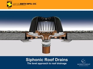
- 1. Siphonic Roof Drains The level approach to roof drainage
- 2. Siphonic Roof Drains Introduction/Brief Summary 1 Siphonic Roof Drain Sales Opportunity 2 Basic Principle of Siphonic Roof Drainage 3 Benefits of Siphonic Roof Drainage 4 Siphonic Roof Drain Models 5-6 Installation 7 Applications 8 Cost Savings 9 Case Studies 10 - 19 Listings/Certifications/Codes/Standards 20 Engineering Resources 21 Summary of the Benefits 22
- 3. Introduction/ Brief Summary Siphonic Roof Drainage – A Short History - Invented and patented in 1968, the concept was primarily used in Scandinavia during the 1970s and later in Europe and the rest of the world. - First U.S. building using siphonic drainage - Boston Convention Center, 1999. - “Siphonic Roof Drainage Fundamentals,” PM Engineer Magazine, 2001. - IKEA Home Furnishings imports technology into the U.S. starting in 2002. - ANSI/ASME A112.6.9 “Siphonic Roof Drains,” 2005. - ASPE Work Group 45 “Siphonic Roof Drainage Design”. - Jay R. Smith Mfg. Co. develops first U.S. made siphonic roof drain. Siphonic Roof Drain Anatomy – What is a siphonic roof drain? - Looks much like a traditional roof drain. -The distinguishing feature is the air baffle. -The air baffle is engineered and tested to prevent air from entering the piping system at peak flows. 1
- 4. Sales Opportunity Benefits to the owner, engineer and contractor Reduced building costs – less material, fewer vertical stacks, less excavation, backfill, ground work and exterior underground piping. Design flexibility – level pipe installation, stack and horizontal pipe location are highly flexible simplifying coordination with other building elements. Save money in time, material and site preparation – smaller pipe sizes, minimized installation costs. Sales opportunity for representatives Innovative and efficient roof drainage solution especially for low rise buildings with large footprints and flat roofs. Strong interest already exists among construction/engineering community. Product looks like and installs like a traditional roof drain unlike European products. Product uses existing and familiar accessories and allows use of existing pipe, fitting and coupling products (no specialized pipe). New construction or retrofit potential (easy replacement of drainage piping). 2
- 5. Main Principles The Siphon Principle - A well understood hydraulic principle with many useful applications. - Discharge end is lower than the level of fluid in the reservoir. - A continuous and closed drainage path induces flow by gravity. - Atmospheric pressure becomes the driving force pushing the fluid through the tube to the lower point of discharge. - Path of siphon tube is irrelevant to the fluid’s ability to flow, i.e. could be flat and level. Traditional roof drainage Siphonic roof drainage Open outlets allow water and air to enter. “Closed” outlets – air baffle promotes “full-bore” flow. Pitched horizontal piping induces flow. Horizontal piping is not pitched. Atmospheric pressure throughout the system. Atmospheric pressure pushes water into the system. Capacity is limited by drain size and water depth. Capacity is determined by piping and elevation difference. Piping is only ½ to 2/3 full. Piping primes and operates 100% full. 3
- 6. Benefits of Siphonic Roof Drainage Why you should consider a siphonic roof drain system: • Reduced material costs - smaller pipe diameters means less $. • Reduced underslab work and building costs - level pipe installation overhead with fewer vertical stacks. • Pipe locations are highly flexible (horizontal and stack). • Higher flow velocity - driving head up to 100 times that of traditional system. • Reduced exterior excavation, backfill and underground piping and structures. • Opportunity to economically enable rainwater harvesting. 4
- 7. Siphonic Roof Drain Models Fig. no. 1005 (15 ¼” diameter) Function: For use in engineered siphonic roof drainage systems in flat roof of any construction. Internal air baffle creates siphonic drainage action producing a more efficient drainage than conventional roof drains. Regularly Furnished: Duco Cast Iron Body, Flashing Clamp, Air Baffle and Polyethylene Dome. Available with Male Thread and No-Hub Outlets Outlet Sizes: 2”, 2 ½”, 3” and 4” Fig. no. 1605 (6” diameter) Function: For use in engineered siphonic roof drainage systems for gutters, parapets, small balconies, sills, cornices, marquees and other small overhanging areas where drainage of rainwater is required. Air baffle creates siphonic drainage action producing a more efficient drainage than conventional gutter drains. Regularly Furnished: Duco Cast Iron Body with Combination Flashing Clamp and Air Baffle. Available with Male Thread and No-Hub Outlets Outlet Size: 2” 5
- 8. Siphonic Roof Drain Models Fig. no. 1005 (15 ¼” diameter) Product data is provided to the specifier for outlet size selection and hydraulic calculations. Sizing is a function of the roof runoff factor, design rainfall intensity and the area draining to the roof drain. 6
- 9. Installation Fig. no. 1005, Low Profile Dome Poured Concrete Fig. No. 1605 Low Profile Gutter Drain Drain set in poured roof deck slab. Flashing is secured by a non-puncturing flashing clamp. Precast Deck Insulated Deck Drain with underdeck clamp -C used where roof drain openings are presleeved or sawed-out in the slab. May be used in any slab or deck. NOTE: Drain flange rests in a recessed portion of the deck, eliminating sump receiver. Drain with sump receiver -R and underdeck clamp -C. The sump receiver is a square metal plate that accepts the drain body flange and eliminates the puddle of water surrounding the drain. Gutter drain set in poured roof deck slab. Flashing is secured by a non-puncturing flashing clamp.1 Product design uses all existing installation accessories. Standard installation procedures apply. 7
- 10. Applications Siphonic systems are especially ideal for low rise buildings with large footprints and flat roofs such as: Airport Terminals Convention Centers Aircraft Hangers Warehouses Covered malls Factories Train Stations Office Complexes Retail Distribution Centers 8
- 11. Cost Savings 1. Roof Drain & Branch 2. Horizontal Manifolds 3. Vertical Stacks 7,840 sq. ft. - Roof surface 3.25 in/hr - Rainfall intensity 15,685 sq. ft. - Roof surface 3.25 in/hr - Rainfall intensity 63,940 sq. ft. - Roof surface 3.25 in/hr - Rainfall intensity Traditional: 5 inch – pipe size (IPC 2000, table 1106.2), 52% full $843 – cost for 10 feet of pipe and 1 inch insulation Traditional: 10 inches – pipe size (IPC 2000, Traditional: 12 inches – pipe size (IPC 2000, table 1106.2), 25% full $1,488 – cost for 10 feet of pipe 3 inch – siphonic pipe size 6 inches – siphonic pipe size $515 – cost for 10 feet of pipe and 1 inch insulation $610 – cost for 10 feet of pipe and 1 inch insulation table 1106.3), 52% full $1,057 – cost for 10 feet of pipe and 1 inch insulation 8 inches – pipe size $627 – cost for 10 feet of pipe 9
- 12. Case Studies Siphonic systems customers include institutional, commercial & retail facilities. Boston Convention Center, Boston, MA IKEA Home Furnishings, Bloomington, MN IKEA Home Furnishings, Stoughton,MA IKEA Home Furnishings, Atlanta, GA 10
- 13. Case Studies Boston Convention and Exhibition Center, South Boston, MA SUMMER ST STORM DRAIN Traditional Gravity System ??? TRADITIONAL GRAVITY FLOW SYSTEM SUMMER ST STORM DRAIN Siphonic Solution PROPOSED UV DRAIN SYSTEM 11
- 14. Case Studies Boston Convention and Exhibition Center, South Boston, MA 12
- 15. Case Studies IKEA Home Furnishings, Stoughton, MA 13
- 16. Case Studies IKEA Home Furnishings, Stoughton, MA 14
- 17. Case Studies IKEA Home Furnishings, Bloomington, MN 15
- 18. Case Studies IKEA Home Furnishings, Bloomington, MN Siphonic Piping Overhead in Merchandise Warehouse: Maximum Clear Height 16
- 19. Case Studies IKEA Home Furnishings, Bloomington, MN Installation Drawing Detail 17
- 20. Case Studies IKEA Home Furnishings, Atlanta, GA 18
- 21. Case Studies IKEA Home Furnishings, Atlanta, GA Service road and rear of store where storm drainage is piped to retention pond off site. 19
- 22. Listings/Certifications Fully tested and certified in accordance with ANSI/ASME A112.6.9 “Siphonic Roof Drains” Note: Hydraulic tests were performed at CRM Laboratory, United Kingdom, under the supervision of HR Wallingford, on a test rig conforming to the ASME Standard A112.6.9-2005. IAPMO Listed. 20
- 23. Engineering Resources Contractors and engineers will typically seek out available products to apply siphonic roof drainage on their projects. “Selling the Concept” is primarily an RMS effort. We have started this effort and will continue to do so. Inquiries by your customers about engineering/design should be referred to RMS for more information. Inquiries by our clients about product availability will be referred to Jay R. Smith or local representatives. RMS has developed a software package to simplify design, assure consistency and enhance accuracy of the results. Initial design services would be by RMS to assure quality and accuracy. Other engineers will be trained by RMS to design systems and use the software. This approach differs significantly from the current competition. They intend to keep design in house thereby depriving engineers and contractors of limited budget. Clients will resist this and favor the Smith/RMS approach. We support open specification and in-house capability, not proprietary outsourcing methods. 21
- 25. It’s Been Done. It Works. It Saves Money. Siphonic Roof Drains The level approach to roof drainage