1. 1
TELE3113 Analogue and Digital Communications
Tutorial 4
I. P ROBLEM 1
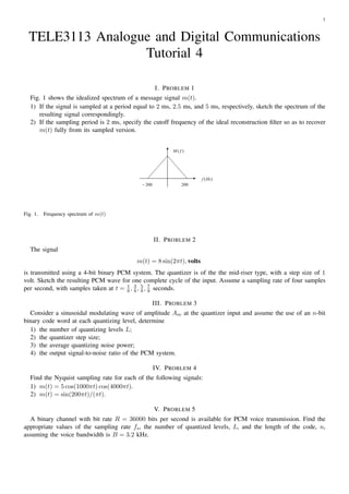
Fig. 1 shows the idealized spectrum of a message signal m(t).
1) If the signal is sampled at a period equal to 2 ms, 2.5 ms, and 5 ms, respectively, sketch the spectrum of the
resulting signal correspondingly.
2) If the sampling period is 2 ms, specify the cutoff frequency of the ideal reconstruction filter so as to recover
m(t) fully from its sampled version.
M( f )
f (Hz )
− 200 200
Fig. 1. Frequency spectrum of m(t)
II. P ROBLEM 2
The signal
m(t) = 8 sin(2πt), volts
is transmitted using a 4-bit binary PCM system. The quantizer is of the the mid-riser type, with a step size of 1
volt. Sketch the resulting PCM wave for one complete cycle of the input. Assume a sampling rate of four samples
per second, with samples taken at t = 8 , 3 , 5 , 7 seconds.
1
8 8 8
III. P ROBLEM 3
Consider a sinusoidal modulating wave of amplitude Am at the quantizer input and assume the use of an n-bit
binary code word at each quantizing level, determine
1) the number of quantizing levels L;
2) the quantizer step size;
3) the average quantizing noise power;
4) the output signal-to-noise ratio of the PCM system.
IV. P ROBLEM 4
Find the Nyquist sampling rate for each of the following signals:
1) m(t) = 5 cos(1000πt) cos(4000πt).
2) m(t) = sin(200πt)/(πt).
V. P ROBLEM 5
A binary channel with bit rate R = 36000 bits per second is available for PCM voice transmission. Find the
appropriate values of the sampling rate fs , the number of quantized levels, L, and the length of the code, n,
assuming the voice bandwidth is B = 3.2 kHz.