![Structural FA The Top Level Design (entity) of a 1-bit Full-Adder looks like this: A B Cout Cin FA_1 Sum ,[object Object],entity FA_1 is port(A,B,Cin : in std_logic; Sum, Cout : out std_logic); end; end;](data:image/gif;base64,R0lGODlhAQABAIAAAAAAAP///yH5BAEAAAAALAAAAAABAAEAAAIBRAA7)
Recomendados
Mais conteúdo relacionado
Mais procurados
Mais procurados (20)
Destaque
Semelhante a Structural vhdl
Semelhante a Structural vhdl (20)
Último
Último (20)
Structural vhdl
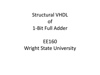
- 1. Structural VHDLof1-Bit Full AdderEE160Wright State University
- 4. In structural modeling, the internal details of an entity are specified by an architecture body that contains interconnected components. For the FA example, we must connect our XOR_2, AND_2, and OR_2 gates appropriately, using intermediate signals where necessary. The next slide shows how the components must be connected together. The yellow wires are necessary intermediate signals. Structural FA
- 5. Structural FA FA_1 A XOR_2 A sig(0) A XOR_2 Sum B Z B B Z Cin A AND_2 B sig(1) Z A Cout OR_2 B Z A AND_2 sig(2) B Z
- 6. Structural FA The left side is the component declaration, the right side is component instantiation. The bolded ports are the component’s ports. The commented U4 shows implicit connection as opposed to explicit, which is functionally equivalent. begin U0: XOR_2 port map(A=>A, B=>B, Z=>sig(0)); U1: XOR_2 port map(A=>sig(0), B=>Cin, Z=>Sum); U2: AND_2 port map(A=>Cin, B=>sig(0), Z=>sig(1)); U3: AND_2 port map(A=>A, B=>B, Z=>sig(2)); U4: OR_2 port map(A=>sig(1), B=>sig(2), Z=>Cout); --U4: OR_2 port map(sig(1), sig(2), Cout); --functionally the same end; architecture STRUCT of FA_1 is component XOR_2 port(A,B:instd_logic; Z:out std_logic); end component; component AND_2 port(A,B:instd_logic; Z:out std_logic); end component; component OR_2 port(A,B:instd_logic; Z:out std_logic); end component; signal sig : std_logic_vector(2 downto 0);
- 7. Now that you’ve written the code for the FA_1, you can use it as a component in an FA_4, or an add/subtract circuit. Remember that you can connect the ports of an entity to the ports of a component (and vice versa), but you need to create local signals to connect a component to another component within an entity. Structural FA