Beginners Guide to TikTok for Search - Rachel Pearson - We are Tilt __ Bright...
THINK!-16_the Blackbox-Whitebox distinction_2
1. THINK !
The Black box-White box distinction
Often, even experienced modelers have problems with the distinction between
what should be modeled at a certain level versus what is known. When the
black box restriction is not followed, it results in messy Use Case descriptions
that are difficult to manage in a requirements changing environment.
This short text is written with the aim to clear some confusions and to make all
people more aware and proactive in the use case driven development
What is a Use Case?
A Use Case is by definition the interaction between a system and a user of the system (the
so called Actor). When we have identified all the actors that interact with the system, we
have to look at each interaction and describe the exchange at the system level in Use case
specification documents (the so called system level use case descriptions).
The main purpose is to identify the Basic flow of events as well as most of the Alternative
& Exceptional flows. It is very important that the described interaction is of “value” for the
actor and that the system is treated as a “black box”;
i.e. we do NOT know anything of the inside
structure or the components which are
present inside the box.
- A simple discussion about the Black box–White box
distinction in Use Case Modeling.
At the System Level, we are simply not interested
in the internal actions of the system. It is therefore
advisable to always begin each step in the text in
the Use case specification documents with either:
“The actor <description of the activity>…” or
“The system < description of the activity> …. “
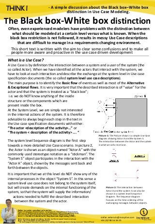
Picture 1: The Picture shows is a simple Use Case
diagram showing Actor A and the System S.
The interaction between the Actor and the system
is what we call a Use Case.
The system level Sequence diagram is the first step
towards a more detailed Use Case scenario. In picture 2,
the Actor is shown as an object named “Actor A” with the
commonly used stereotype notation as a “stickman”. The
“System S” object participates in the interaction with the
“Actor A” object, shown by the messages sent back and
forth between the objects.
It is important that we at this level do NOT show any of the
internal processes in the object “System S”. In this sense a
system level use case does not belong to the system itself,
but will create demands on the internal functioning of the
system, so that the system will supply the information/
actions needed to fulfill the described interaction
between the system and the actor.
Picture 2: The interaction between
Actor A and the system S can also be
shown in a system level Sequence
Diagram. The Sequence diagram
focuses on the time ordering of the
exchanging messages between objects.
Stefan is a senior consultant at Inceptive.
Expert in Exploration, Representation - Visualization & Management of Requirements
with focus on IBM Rational Accelerators for Collaborative Lifecycle Management (CLM).
He is passionate about developing & establishing effective Methods & Processes.
Stefan is a Certified Professional for Requirements Engineering (CPRE).
Stefan Eekenulv is based in Goteborg, Sweden, but likes to speak French in la Grave
after a day of MONOSKI off-pist experiences
"The real voyage of discovery consists not in seeking new landscapes but in having new eyes“ /Marcel Proust
stefan.eekenulv@inceptive.com
+46 (0)708 56 54 05
2. THINK !
Lets say that we have a system which
includes four subunits. For simplicity we
name them 1, 2, 3 and 4. After the
opening of the black box , the four
subunits will now come into play, and
the system level use case between Actor
A and System S, can now be detailed
with the internal messages to the
Subunits.In the same way as for the system level
Use case, we show the internal interactions
between the subunits using a sequence diagram.
It is important to know that the Actor A and the
subunits are on different conceptual levels.
Picture 3: The black box has been opened and the
four subunits are now shown and the internal
messages related to the use case interaction
between Actor A and System S are shown.
Opening the black box creates the white box !
Picture 4: The interaction between Actor A and the subunits
in System S are shown in the same Sequence Diagram.
Internal Use Cases
– Subunit level use cases.
There is nothing to stop us from writing
use cases for the internal communication
between the subunits in System S.
However, when we change conceptual
level, the internal “roles” changes. The
interaction between subunit 2 and
subunit 4, as shown in picture 3 above,
becomes an interaction between the
ACTOR “S 2” and the SYSTEM “4”.
Picture 5a & 5b: The Subunit level Use Case between
ACTOR “S 2” and SYSTEM “4” with white box view of
the internal subunits and their interactions.
The use case description is concentrating on the interaction between the ACTOR “2”
and the SYSTEM “4” and even if we new everything about the internal processes and
subunits in the former subunit 4, that information would NOT be part of this
Subunit level use case description.
3. THINK !
The model structure
When elaborating the use cases for
the “black box” into a description of
the “white box-behavior” we have to be very strict on the Rose model structure. The
basic flow and all the alternative flows for all use case realizations must be modeled in a
interaction diagram (i.e. a sequence diagram or a collaboration diagram)
Picture 6: The interaction between Actor “S 2” and the subunits
in System “4” are shown in the same Sequence Diagram.
Picture 7: Use Case realizations are connected to their
respective Use Cases in the Use Case Realizations diagram.
Modeling of interactions between a system and an actor
when the interaction involves other actors?
If an actor (Actor A) interacts with the system in
a way that will include other actors, we have
to analyze the communication between the
system and the other actors. If the communication
is of no value to those actors alone, and the
interaction is associated with the actor A, this
will be modeled in one use case initiated by the actor A.
Picture 8: Use Case Analysis of Actor A and System
S involving the actors Actor B and Actor C.
If Actor C and Actor B are “passive Actors” to
the system S (i.e. they would not have a
communication with the system if it wasn’t
for Actor A), we will neither write use cases
for the interaction between the system and
Actor B nor between the system and Actor C.
However the use case between the system
and Actor A will include the communication
with those actors as seen in the system level
sequence diagram in picture 9.
Picture 9: System level sequence diagram including all the
actors involved in the Actor A – System S Use case interaction.
4. THINK !
“If you keep track on which level you are dealing
with, Use cases can be very helpful in understanding
and communicating the intention of the interaction.
It is important to remember that what decides if a use
case shall be written or not is the need for structured
written information on the interactions and, most
importantly, how frequent the changes are to this part
of the system.
If the interaction is predicted to change a lot during the
development and very rarely is going to be explained
to non-experts, the written use case is NOT the best
way to represent this knowledge. In these cases (as
often is the case when we go deeper than the system
level) the activity diagram and state machines is much
easier to change and contains a higher degree of
preciseness and logic structure.”
Good luck with your use case modeling !
/ Stefan Eekenulv