
Recomendados
Mais conteúdo relacionado
Mais procurados
Mais procurados (20)
Destaque
Destaque (10)
Semelhante a ROBOMAT
Semelhante a ROBOMAT (20)
ROBOMAT
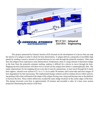
- 1. This project sponsored by General Atomics (GA) focused on the development of a device that can map the interior of a railgun in order to check for bore deterioration. A railgun delivers a projectile at incredibly high speeds by sending a massive amount of current between its two rails through the projectile armature. After each shot, the railgun's bore experiences some deterioration. Furthermore, there is a large amount of aluminum sludge in the bore from the projectile armature melting, making it difficult for a device to move through the bore. Mapping the bore deterioration will allow GA to switch out the railgun bore before it catastrophically fails. The major requirements for the mapping device were that it must be autonomous, it must travel through the 8 meter bore (approx. internal cross section of 2.1 in x 3.1 in) in under 30 minutes, and it must take and store images of bore degradation for later processing. The implemented design solution used two bottom driven rollers and two top guiding rollers that conformed to the shape of the railgun forcing cone; using said forcing cone as the platform to traverse the bore. These rollers effectively avoided the main sludge locations in the corner edges of the bore. This design traversed a test bore in approximately 29 minutes and recorded a video of a laser cross section projection illuminating the interior of the bore.
- 2. The ROBO MAT is an autonomous mapping tool that has the capability to effectively measure railgun bore degradation (specifically designed for General Atomics’ Blitzer Railgun). It is important to note that the ROBO MAT was not tested in the actual Blitzer Railgun Bore due to the time constraint of the project; however, it was tested with a fabricated bore model. As discussed in the main location of melted armature sludge is along the edge corners of the railgun bore. The ROBO MAT design effectively avoided this section of the railgun bore by using the bore upper and lower forcing cone allowing for easier, less-impeded motion. While there is some sludge in the bore on the upper and lower forcing cone areas, it is quite minimal and significantly less pronounced than the sludge on the bore corners. It is important to note that the exact amount, size, and location of the sludge in the bore cannot be completely defined, due to the fact that it changes after each railgun projectile launch test. Thus, the ROBO MAT utilized the fact that while the dispersion of sludge along the forcing cone varies, its intensity and magnitude is always minimal. The ROBO MAT design featured four 3D-printed Acrylonitrile Butadiene Styrene (ABS) plastic rollers. These rollers matched the radius of the railgun forcing cone, thus creating the greatest amount of surface area between the rollers and said forcing cone. This large contact area allowed the rollers to grip the forcing cone, which in turn lead to better traction and movement. Two of the rollers were positioned at the bottom of the chassis and were driven by DC motor. Since these rollers were driven, higher traction was desired, thus the bottom rollers were wrapped in O-rings, increasing the coefficient of friction between the rollers and the forcing cone. The other two rollers were positioned at the top of the chassis and were suspended by springs to create a normal force between the top rollers and the upper forcing cone. It is important to note that the springs were located within the chassis body. The spring suspension system was very important for the ROBO MAT design; it allowed the top-guiding rollers assembly to have a linear motion and move downward as either the bottom rollers went over sludge or as the top roller came into contact with sludge. Furthermore, the top rollers promoted center alignment of the entire cart. The Raspberry Pi B+ microcontroller was the brain of the ROBO MAT. The Raspberry Pi controlled all of the components of the cart and allowed for wireless communication between the cart operator and the cart itself. The bottom two rollers were both driven by the same drivetrain system. The motors were mounted onto the chassis and translated torque to the drive rollers through a multi-gear system. The selection of gear tooth size was twofold: desired output torque and cart speed. These motors were controlled and operated using the Raspberry Pi B+ and an Arduino motor controller board. The motor controller board effectively allowed the Raspberry Pi to control both motors through Pulse Width Modulation (PWM). An essential component was connected to the back of the chassis: the tracer wheel. The tracer wheel assembly consisted of a simple wheel with O-rings for better traction, a torsion spring that held the tracer wheel against the bottom forcing cone, and a high resolution, 360 counts/rev (CPR) encoder to record wheel movement. The torsion spring ensured accuracy of the tracer wheel encoder by making sure the tracer wheel was always in contact with the bottom forcing cone. The Raspberry Pi read the information from the encoder and converted the clicks/rev to distance. The collected distance was displayed and updated on the cart operator’s laptop through the wireless Raspberry Pi
- 3. terminal interface. Thus, the tracer wheel was essential to determine the cart location in the bore. In addition, the tracer wheel allowed the cart operator to determine if the cart had become jammed in the bore by examining the encoder data. If the encoder displayed no change in movement, the cart had become jammed. The optics system used is the direct tool for mapping the bore degradation. This approach was the same as General Atomics’ method. The laser beam hits the conical mirror, creating a projected image of the railgun bore (perpendicular to the direction of motion of the cart) and any deteriorations it may have; this image is then captured using a high resolution camera. Said image is then stored and used for post-process analysis. The differentiation of the optics system between GA’s approach and the ROBO MAT design stemmed from the fact that the ROBO MAT continuously moved through the bore without stopping (GA’s cart stopped each time it captured an image). As a result the laser projected image of the bore is captured through video rather than pictures. However, it should be noted that the ROBO MAT system has the capability to both continuously stop and start moving and to take still images rather than video depending on any different necessary requirements. The video file was saved on the microcontroller mini- SD card for post-process analysis. It is important to note that the scope of this project did not include the analysis of the collected data, only the collection procedure.