SlideShare uma empresa Scribd logo
1 de 72
Baixar para ler offline
Controller Area Network
    q Fundamentals                        q Physical Layer
        • How it all began...                • Message Coding
        • Overview                           • Synchronization
        • Basic Concepts                     • Bit Timing / Bit
    q Data Link Layer                          Construction
       • Bus Access Arbitration              • CAN Bus Lines
       • Frame Formats                    q      CAN Implementations
       • Error Detection                  q      User Benefits
       • Error Handling                   q      Application Examples
       • Protocol Versions                q      Siemens CAN Devices
         (Standard /Extended)


                                                                Siemens Microelectronics, Inc.
                                                                October 98
                                CANPRES Version 2.0             Slide 1


                                Page 1
How it all began...


                                                                     Air
             Engine      Anti-                          Lighting    Con-
             Control     Lock                                       dition                          Power
                        Brakes                                                                      Locks


                                 Dash-
                                 board

                                                                                                    Airbag
                                                        Power
             Trans-     Active                          Seats
             mission   Suspen-                                     Power
             Control     sion                                       Win-
                                                                   dows
                                                                   Siemens Microelectronics, Inc.
                                                                   October 98
                                  CANPRES Version 2.0              Slide 2


•The development of CAN began when more and more electronic
devices were implemented into modern motor vehicles. Examples of
such devices include engine management systems, active suspension,
ABS, gear control, lighting control, air conditioning, airbags and central
locking. All this means more safety and more comfort for the driver and
of course a reduction of fuel consumption and exhaust emissions.


                                 Page 2
How it all began… (cont.)


                                                                       Air
             Engine     Anti-                             Lighting    Con-
             Control    Lock                                          dition                          Power
                       Brakes                                                                         Locks


                                   Dash-
                                   board

                                                                                                      Airbag
                                                          Power
            Trans-      Active                            Seats
            mission    Suspen-                                       Power
            Control      sion                                         Win-
                                                                     dows
                                                                     Siemens Microelectronics, Inc.
                                                                     October 98
                                    CANPRES Version 2.0              Slide 3


• improve the behavior of the vehicle even further, it was necessary
 To
for the different control systems (and their sensors) to exchange
information. This was usually done by discrete interconnection of the
different systems (i.e. point to point wiring). The requirement for
information exchange has then grown to such an extent that a cable
network with a length of up to several miles and many connectors was
required. This produced growing problems concerning material cost,
production time and reliability.


                                   Page 3
How it all began… (cont.)


                                                                          Air
             Engine     Anti-                                 Lighting   Con-
             Control    Lock                                             dition                           Power
                       Brakes                                            CAN                              Locks
              CAN      CAN                                     CAN
                                                                                                          CAN
        High Speed                     Dash-                     Low Speed


                                 CAN


                                                     CAN
                                       board
                                                                                                          CAN
                                                               CAN
                                                                                                          Airbag
              CAN       CAN                                   Power
                                                              Seats      CAN
             Trans-     Active
             mission   Suspen-                                           Power
             Control     sion                                             Win-
                                                                         dows
                                                                         Siemens Microelectronics, Inc.
                                                                         October 98
                                        CANPRES Version 2.0              Slide 4


•The solution to this problem was the connection of the control systems
via a serial bus system. This bus had to fulfill some special
requirements due to its usage in a vehicle.
•With the use of CAN, point-to-point wiring is replaced by one serial bus
connecting all control systems. This is accomplished by adding some
CAN-specific hardware to each control unit that provides the "rules" or
the protocol for transmitting and receiving information via the bus.


                                       Page 4
Overview


                               Specified by Robert Bosch                                                  Industrial
                  CAN          GmbH, Germany
                  Spec
                                      ISO/OSI                       Automotive
                                      SAE
                                                                        à Distributed Controls


                                   CAL, CANopen (CiA),            140

             7   Application Layer DeviceNet (ODVA),              120
                                                                  100
                                   SDS (Honeywell)
                         ...


                                                                  80
                                                                                                          CAN


                                     }
                                                                  60
                                                                                                          Nodes

             2   Data Link Layer                                  40
                                                                  20
                                         CAN                       0


                                                                        1997

                                                                               1998

                                                                                       1999

                                                                                              2000
             1    Physical Layer


                                                                                      Siemens Microelectronics, Inc.
                                                                                      October 98
                                            CANPRES Version 2.0                       Slide 5


•CAN or Controller Area Network is an advanced serial bus system that
efficiently supports distributed control systems. It was initially developed
for the use in motor vehicles by Robert Bosch GmbH, Germany, in the
late 1980s, also holding the CAN license.
•CAN is internationally standardized by the International Standardization
Organization (ISO) and the Society of Automotive Engineers (SAE).
•The CAN protocol uses the Data Link Layer and the Physical Layer in
the ISO - OSI model. There are also a number of higher level protocols
available for CAN.
•CAN is most widely used in the automotive and industrial market
segments. Typical applications for CAN are motor vehicles, utility
vehicles, and industrial automation. Other applications for CAN are
trains, medical equipment, building automation, household appliances,
and office automation. Due to the high volume production in the
automotive and industrial markets, low cost protocol devices are
available.
•There are about 20 million CAN nodes in use worldwide. By the year
2000 the number of nodes is estimated to be 140 million.
•Examples of vehicle bus systems, other than CAN, are A-BUS from
Volkswagen, VAN or Vehicle Area Network, from Peugeot and Renault,
and J1850 from Chrysler, General Motors and Ford.
•CAN is clearly the leading vehicle bus protocol in Europe.


                                           Page 5
Basic Concepts


        n   Multimaster                                                         n Easy
                                    CAN
            Concept                                                          connection/
                                   Nodes
                                                                            disconnection
        n Number of                                                            of nodes
            nodes         Node A                   Node n
        not limited by     e.g.                     e.g.                      n   Broadcast/
          protocol         ABS                     EMS                            Multicast
                                                                                  capability
          n No node
         addressing,
          Message
           identifier          CAN-Bus
           specifies           (logical)
         contents &
            priority

                                                            Siemens Microelectronics, Inc.
                                                            October 98
                                   CANPRES Version 2.0      Slide 6


•CAN is a multi-master bus with an open, linear structure with one logic
bus line and equal nodes. The number of nodes is not limited by the
protocol.
• the CAN protocol, the bus nodes do not have a specific address.
 In
Instead, the address information is contained in the identifiers of the
transmitted messages, indicating the message content and the priority
of the message.
•The number of nodes may be changed dynamically without disturbing
the communication of the other nodes.
•Multicasting and Broadcasting is supported by CAN.


                                   Page 6
Basic Concepts (cont.)


                                   Node A                      Node n
                                                                                                  n Sophisti-
                                   e.g. ABS                 e.g. EMS                              cated Error
         Application
                                                                                                  Detection /
                                     e.g.                                                          Handling
                                                              e.g.
         Host-Controller           80C166                  C167CR
                                                                                               n NRZ Code
                                                           or C515C
                                                                                               + Bit Stuffing
         CAN-Controller            81C9x                        CAN                                  for
                                                                                                Synchroni-
         CAN-Transceiver                                                                          zation

                           CAN_H                   UDiff                                       n   Bus access
                    120                                                      120
         CAN-Bus Ohm                                                         Ohm                      via
                           CAN_L            EMI               40m / 130 ft                         CSMA/CD
                                                               @ 1 Mbps                             w/ AMP
                                                                              Siemens Microelectronics, Inc.
                                                                              October 98
                                              CANPRES Version 2.0             Slide 7


•CAN provides sophisticated error-detection and error handling
mechanisms such as CRC check, and high immunity against
electromagnetic interference. Erroneous messages are automatically
retransmitted. Temporary errors are recovered. Permanent errors are
followed by automatic switch-off of defective nodes. There is
guaranteed system-wide data consistency.
•The CAN protocol uses Non-Return-to-Zero or NRZ bit coding. For
synchronization purposes, Bit Stuffing is used.
•There is a high data transfer rate of 1000 kilobits per second at a
maximum bus length of 40 meters or 130 feet when using a twisted wire
pair which is the most common bus medium used for CAN. Message
length is short with a maximum of 8 data bytes per message and there
is a low latency between transmission request and start of transmission.
•The bus access is handled via the advanced serial communications
protocol Carrier Sense Multiple Access/Collision Detection with Non-
Destructive Arbitration. This means that collision of messages is
avoided by bitwise arbitration without loss of time.


                                              Page 7
Basic Concepts -
       CAN Bus Characteristics - Wired-AND

              Two logic states
                                                                       “ = recessive
                                                                        1”
              possible on the bus:
                                                                       “ = dominant
                                                                        0”
              “ = recessive
               1”
              “ = dominant
               0”

              A   B   C    BUS
              D   D   D     D
                                     As soon as one node nodes transmits
              D   D   R     D
                                     a dominant bit (zero):
              D   R   D     D
                                     Bus is in the dominant state.
              D   R   R     D
              R   D   D     D
              R   D   R     D
                                     Only if all nodes transmit
              R   R   D     D
                                     recessive bits (ones):
              R   R   R     R
                                     Bus is in the recessive state.


                                                                 Siemens Microelectronics, Inc.
                                                                 October 98
                                       CANPRES Version 2.0       Slide 8


•There are two bus states, called "dominant" and "recessive".
•The bus logic uses a "Wired-AND" mechanism, that is, "dominant bits"
(equivalent to the logic level "Zero") overwrite the "recessive" bits
(equivalent to the logic level "One" ).


                                      Page 8
Basic Concepts -
       CAN Bus Characteristics - Wired-AND (cont.)

                                                                                                   5V

                               Bus State: recessive (High)

              CAN-Bus
                                        L                                L             L
           (single logical
              bus line)

                              R T                      R T                     R T
                                recessive


                                                                  recessive


                                                                                 recessive
                             Node A                 Node B                    Node C
                                                                                  Siemens Microelectronics, Inc.
                                                                                  October 98
                                            CANPRES Version 2.0                   Slide 9


•Only if all nodes transmit recessive bits (ones), the Bus is in the
recessive state.


                                            Page 9
Basic Concepts -
       CAN Bus Characteristics - Wired-AND (cont.)

                                                                                                  5V

                              Bus State: dominant (Low)

             CAN-Bus
                                     H                                  L             L
          (single logical
             bus line)

                             R T                      R T                     R T


                                                                 recessive


                                                                                recessive
                               dominant


                            Node A                 Node B                    Node C
                                                                                 Siemens Microelectronics, Inc.
                                                                                 October 98
                                           CANPRES Version 2.0                   Slide 10


• soon as one node transmits a dominant bit (zero), the bus is in the
 As
dominant state.


                                          Page 10
Bus Access and Arbitration: CSMA/CD w/ AMP


                   Node X
                   Node A
                   Node B
                   Node C


                                            Start Identifier Field
                Arbitration                   Bit
                              Node A
                  phase
                              Node B
               Remainder      Node C
                Transmit      CAN Bus
                Request
                               Node B loses Arbitration        Node C loses Arbitration
                                                                     Siemens Microelectronics, Inc.
                                                                     October 98
                                         CANPRES Version 2.0         Slide 11


•The CAN protocol handles bus accesses according to the concept
called “ Carrier Sense Multiple Access with Arbitration on Message
Priority” This arbitration concept avoids collisions of messages whose
         .
transmission was started by more than one node simultaneously and
makes sure the most important message is sent first without time loss.
In the picture above you see the trace of the transmit pins of three bus
nodes called A, B and C, and the resulting bus state according to the
wired-AND principle.
• two or more bus nodes start their transmission at the same time after
 If
having found the bus to be idle, collision of the messages is avoided by
bitwise arbitration. Each node sends the bits of its message identifier
and monitors the bus level.
• a certain time nodes A and C send a dominant identifier bit. Node B
 At
sends a recessive identifier bit but reads back a dominant one. Node B
loses bus arbitration and switches to receive mode. Some bits later
node C loses arbitration against node A. This means that the message
identifier of node A has a lower binary value and therefore a higher
priority than the messages of nodes B and C. In this way, the bus node
with the highest priority message wins arbitration without losing time by
having to repeat the message.
•Nodes B and C automatically try to repeat their transmission once the
bus returns to the idle state. Node B loses against node C, so the
message of node C is transmitted next, followed by node B’ message.
                                                                  s
• is not permitted for different nodes to send messages with the same
 It
identifier as arbitration could fail leading to collisions and errors.
                                        Page 11
Frame Formats - Overview


            q Existing Frame Formats:


                     Data                 Remote                          Error
                    Frame                 Frame                          Frame

                                                                Inter-
                             Overload                          frame
                              Frame                            Space


                                                                          Siemens Microelectronics, Inc.
                                                                          October 98
                                         CANPRES Version 2.0              Slide 12


•These are the existing Frame formats which are now discussed in the
following slides.


                                        Page 12
Frame Formats - Data Frame


                                                              Siemens Microelectronics, Inc.
                                                              October 98
                                        CANPRES Version 2.0   Slide 13


• "Data Frame" is generated by a CAN node when the node wishes to
 A
transmit data. The Standard CAN Data Frame is shown above. The frame
begins with a dominant Start Of Frame bit for hard synchronization of all
nodes.
•The Start of Frame bit is followed by the Arbitration Field consisting of 12 bits:
The 11-bit Identifier, which reflects the contents and priority of the message,
and the Remote Transmission Request bit. The Remote transmission request
bit is used to distinguish a Data Frame (RTR = dominant) from a Remote
Frame (RTR = recessive).
•The next field is the Control Field, consisting of 6 bits. The first bit of this field
is called the IDE bit (Identifier Extension) and is at dominant state to specify
that the frame is a Standard Frame. The following bit is reserved and defined
as a dominant bit. The remaining 4 bits of the Control Field are the Data
Length Code (DLC) and specify the number of bytes of data contained in the
message (0 - 8 bytes).
•The data being sent follows in the Data Field which is of the length defined by
the DLC above (0, 8, 16, ...., 56 or 64 bits).
•The Cyclic Redundancy Field (CRC field) follows and is used to detect
possible transmission errors. The CRC Field consists of a 15 bit CRC
sequence, completed by the recessive CRC Delimiter bit.
•The next field is the Acknowledge Field. During the ACK Slot bit the
transmitting node sends out a recessive bit. Any node that has received an
error free frame acknowledges the correct reception of the frame by sending
back a dominant bit (regardless of whether the node is configured to accept
that specific message or not). From this it can be seen that CAN belongs to
the "in-bit-response" group of protocols. The recessive Acknowledge Delimiter
completes the Acknowledge Slot and may not be overwritten by a dominant
bit.
•                                     Page 13
 Seven recessive bits (End of Frame) end the Data Frame.
Frame Formats - Remote Frame


                                                       Siemens Microelectronics, Inc.
                                                       October 98
                                 CANPRES Version 2.0   Slide 14


•Generally data transmission is performed on an autonomous basis with
the data source node (e.g. a sensor) sending out a Data Frame. It is
also possible, however, for a destination node to request the data from
the source by sending a Remote Frame.
•There are 2 differences between a Data Frame and a Remote Frame.
Firstly the RTR-bit is transmitted as a dominant bit in the Data Frame
and secondly in the Remote Frame there is no Data Field. In the very
unlikely event of a Data Frame and a Remote Frame with the same
identifier being transmitted at the same time, the Data Frame wins
arbitration due to the dominant RTR bit following the identifier. In this
way, the node that transmitted the Remote Frame receives the desired
data immediately.


                                Page 14
Frame Formats - Remote Frame (cont.)


            q Remote Frame scenario


                               How hot is the oil ?
                                                              Node B
               Node A   Remote Frame; Identifier 'oil_tmp'
                                                             (oil temp.-
                                      115 °C !                sensor)

                         Data Frame; Identifier 'oil_tmp';
                          contains desired information         ~~~~
                                                             115°C
                                                              ~~~~~


                                                              Siemens Microelectronics, Inc.
                                                              October 98
                                       CANPRES Version 2.0    Slide 15


• a node wishes to request the data from the source, it sends a
 If
Remote Frame with an identifier that matches the identifier of the
required Data Frame. The appropriate data source node will then send
a Data Frame as a response to this remote request.


                                      Page 15
Frame Formats - Error Frame


               q Active Error Frame: Used for error signaling


                                                                  Siemens Microelectronics, Inc.
                                                                  October 98
                                            CANPRES Version 2.0   Slide 16


• Error Frame is generated by any node that detects a bus error. The Error
 An
Frame consists of 2 fields, an Error Flag field followed by an Error Delimiter
field. The Error Delimiter consists of 8 recessive bits and allows the bus nodes
to restart bus communications cleanly after an error. There are, however, two
forms of Error Flag fields. The form of the Error Flag field depends on the
“error status”of the node that detects the error.
• an “
 If      error-active” node detects a bus error then the node interrupts
transmission of the current message by generating an “       active error flag” The
                                                                               .
“active error flag” is composed of six consecutive dominant bits. This bit
sequence actively violates the bit stuffing rule. All other stations recognize the
resulting bit stuffing error and in turn generate Error Frames themselves. The
Error Flag field therefore consists of between six and twelve consecutive
dominant bits (generated by one or more nodes). The Error Delimiter field
completes the Error Frame. After completion of the Error Frame bus activity
returns to normal and the interrupted node attempts to resend the aborted
message.
• an “
 If     error passive” node detects a bus error then the node transmits an
“passive Error Flag” followed, again, by the Error Delimiter field. The “    passive
Error Flag” consists of six consecutive recessive bits, and therefore the Error
Frame (for an “    error passive” node) consists of 14 recessive bits (i.e. no
dominant bits). From this it follows that, unless the bus error is detected by the
node that is actually transmitting (i.e. is the bus master), the transmission of an
Error Frame by an “    error passive” node will not affect any other node on the
network. If the bus master node generates an “       error passive flag” then this
may cause other nodes to generate error frames due to the resulting bit
stuffing violation.


                                         Page 16
Frame Formats - Overload Frame


          q Overload Frame: Used to delay next CAN message


                                                               Siemens Microelectronics, Inc.
                                                               October 98
                                         CANPRES Version 2.0   Slide 17


• Overload Frame has the same format as an “
 An                                                  active” Error Frame.
An Overload Frame, however can only be generated during Interframe
Space. This is the way then an Overload Frame can be differentiated
from an Error Frame (an Error Frame is sent during the transmission of
a message). The Overload Frame consists of 2 fields, an Overload Flag
followed by an Overload Delimiter. The Overload Flag consists of six
dominant bits followed by Overload Flags generated by other nodes (as
for “active error flag” again giving a maximum of twelve dominant bits).
                       ,
The Overload Delimiter consists of eight recessive bits. An Overload
Frame can be generated by a node if due to internal conditions the
node is not yet able to start reception of the next message. A node may
generate a maximum of 2 sequential Overload Frames to delay the start
of the next message.


                                       Page 17
Frame Formats - Interframe Space


             q Interframe Space: Separates a frame (of whatever type) from a
               following Data or Remote Frame.


                                                                  Siemens Microelectronics, Inc.
                                                                  October 98
                                         CANPRES Version 2.0      Slide 18


•Interframe Space separates a preceeding frame (of whatever type)
from a following Data or Remote Frame. Interframe space is composed
of at least 3 recessive bits, these bits are termed the Intermission. This
time is provided to allow nodes time for internal processing before the
start of the next message frame. After the Intermission, for error active
CAN nodes the bus line remains in the recessive state (Bus Idle) until
the next transmission starts.
•The Interframe Space has a slightly different format for error passive
CAN nodes which were the transmitter of the previous message. In this
case, these nodes have to wait another eight recessive bits called
Suspend Transmission before the bus turns into bus idle for them after
Intermission and they are allowed to send again. Due to this mechanism
error active nodes have the chance to transmit their messages before
the error passive nodes are allowed to start a transmission.


                                       Page 18
Error Detection - Overview


         q Detected Errors:


                      CRC                   Form                     Stuff
                      Error                 Error                    Error


                              ACK                             Bit
                              Error                          Error


                                                                      Siemens Microelectronics, Inc.
                                                                      October 98
                                       CANPRES Version 2.0            Slide 19


•The CAN protocol provides sophisticated error detection mechanisms
discussed in the following slides.


                                      Page 19
Error Detection - Cyclic Redundancy Check


             q Calculated and received CRC Checksum must match...


                      Node A                                            Node B
                                 Calculated               Calculated
           Idle                CRC Checksum:            CRC Checksum:                             Idle
           Receive                1234h                     1234h                                 Receive
           Transmit                                                                               Transmit
                                 Transmitted              Received
                               CRC Checksum:            CRC Checksum:
                                   1234h                    1234h                              match

            CAN_H                       Data Frame


            CAN_L
                                                                 CRC Sequence
                                                                         Siemens Microelectronics, Inc.
                                                                         October 98
                                           CANPRES Version 2.0           Slide 20


•With the Cyclic Redundancy Check, the transmitter calculates a check
sum for the bit sequence from the start of frame bit until the end of the
Data Field.
•This CRC sequence is transmitted in the CRC Field of the CAN frame.
•The receiving node also calculates the CRC sequence using the same
formula and performs a comparison to the received sequence.


                                         Page 20
Error Detection - Cyclic Redundancy Check (cont.)


            q … otherwise Frame was not received correctly (CRC Error)


                     Node A                                            Node B
                                Calculated               Calculated
          Idle                CRC Checksum:            CRC Checksum:                             Idle
          Receive                1234h                    1235h                                  Receive
          Transmit                                                                               Transmit
                                Transmitted              Received
                              CRC Checksum:            CRC Checksum:
                                  1234h                    1234h                            mismatch
           CAN_H                       Error Frame


           CAN_L

                                                                        Siemens Microelectronics, Inc.
                                                                        October 98
                                          CANPRES Version 2.0           Slide 21


• node B detects a mismatch between the calculated and the received
 If
CRC sequence , then a CRC error has occurred.
•Node B discards the message and transmits an Error Frame to request
retransmission of the garbled frame.


                                        Page 21
Error Detection - Acknowledge


                                     Ack. Field                     q A frame
                                                                      must be
                                                                      acknow-
           Node A      Recessive                                      ledged by
            Idle                                                      at least one
                          TX                                          other node
            Receive
                       Dominant
            Transmit                                                      (otherwise
           Node B      Recessive                                          ACK-Error)
            Idle
            Receive       TX
                       Dominant
            Transmit
                       Recessive
           CAN Bus
            Idle
            Active     Dominant


                                                   Ack. Delimiter
                                          Acknowledge Slot
                                                                    Siemens Microelectronics, Inc.
                                                                    October 98
                                    CANPRES Version 2.0             Slide 22


•With the Acknowledge Check the transmitter checks in the
Acknowledge Field of a message to determine if the Acknowledge Slot,
which is sent out as a recessive bit, contains a dominant bit.
• this is the case, at least one other node, (here node B) has received
 If
the frame correctly.
• not, an Acknowledge Error has occured and the message has to be
 If
repeated. No Error Frame is generated, though.


                                   Page 22
Error Detection - Frame Check


                                                          q No dominant
                                                            bits allowed in
                                                            CRC Delimiter,
                                                            ACK Delimiter,
                                                            End of Frame,
                                1      1 7     3            Intermission
                                                            (Form Error)


                                                             Siemens Microelectronics, Inc.
                                                             October 98
                                    CANPRES Version 2.0      Slide 23


•Another error detection mechanism is the Frame Check. If a transmitter
detects a dominant bit in one of the four segments:

CRC Delimiter,
Acknowledge Delimiter,
End of Frame or
Interframe Space

then a Form Error has occurred and an Error Frame is generated. The
message will then be repeated.


                               Page 23
Error Detection - Bit Monitoring


                                                           q A transmitted bit must
                                                             be correctly read back
                                                             from the CAN bus
                                                             (otherwise Bit Error)
                                                           q Dominant bits may
                 11   1          1                           overwrite recessive
                                                             bits only in the
                                                             Arbitration Field and
                                                             in the Acknowledge
                                                             Slot


                                                                Siemens Microelectronics, Inc.
                                                                October 98
                                     CANPRES Version 2.0        Slide 24


• nodes perform Bit Monitoring: A Bit Error occurs if a transmitter
 All

sends a dominant bit but detects a recessive bit on the bus line or,
sends a recessive bit but detects a dominant bit on the bus line.

• Error Frame is generated and the message is repeated.
 An

•When a dominant bit is detected instead of a recessive bit, no error
occurs during the Arbitration Field or the Acknowledge Slot because
these fields must be able to be overwritten by a dominant bit in order to
achieve arbitration and acknowledge functionality.


                                 Page 24
Error Detection - Bit Stuffing Check


                                                       q 6 consecutive
                                                         bits with same
                                                         polarity are not
                                                         allowed between
                                                         Start Of Frame
                                                         and CRC
                                                         Delimiter
                                                         (otherwise Bit
                                                         Stuffing Error)


                                                           Siemens Microelectronics, Inc.
                                                           October 98
                                 CANPRES Version 2.0       Slide 25


• six consecutive bits with the same polarity are detected between
 If
Start of Frame and the CRC Delimiter, the bit stuffing rule has been
violated.
• stuff error occurs and an Error Frame is generated. The message is
 A
then repeated.


                                Page 25
Error Handling


                       Node A                            Node B               Node C


                        Error                              Error              Error
                                                           reco-              reco-
                       detected                           gnized              gnize
            Idle                                                                d
                                                                   Idle                                 Idle
            Receive               Error Frame                      Receive                              Receive
            Transmit                                               Transmit                             Transmit


           CAN_H                   Data Frame


            CAN_L


                                                                              Siemens Microelectronics, Inc.
                                                                              October 98
                                        CANPRES Version 2.0                   Slide 26


•Detected errors are made public to all other nodes via Error Frames.
•The transmission of the erroneous message is aborted and the frame
is repeated as soon as possible.


                                       Page 26
Error Handling (cont.)


                        REC<=127          REC>127
                          and                or              TEC>255
                        TEC<=127          TEC>127


                         Error              Error            Bus
              Reset      active            passive           off


                                  Re-Initialization only
                                                               Siemens Microelectronics, Inc.
                                                               October 98
                                       CANPRES Version 2.0     Slide 27


•Each CAN node is in one of three error states "error active", "error passive" or
"bus off" according to the value of their internal error counters.
•The error-active state is the usual state after reset. The bus node can then
receive and transmit messages and transmit active Error Frames (made of
dominant bits) without any restrictions. During CAN communication, the error
counters are updated according to quite complex rules. For each error on
reception or transmission, the error counters are incremented by a certain
value. For each successful transaction, the error counters are decremented by
a certain value. The error active state is valid as long as both error counters
are smaller than or equal to 127.
• either the receive or the transmit error counter has reached the value of
 If
128, the node switches to the error-passive state. In the error-passive state,
messages can still be received and transmitted, although, after transmission of
a message the node must suspend transmission. It must wait 8 bit times
longer than error-active nodes before it may transmit another message. In
terms of error signaling, only passive Error Frames (made of recessive bits)
may be transmitted by an error-passive node.
• both error counters go below 128 again due to successful bus
 If
communication, the node switches back to the error-active state.
•One feature of the CAN protocol is that faulty nodes withdraw from the bus
automatically. The bus-off state is entered if the transmit error counter
exceeds the value of 255. All bus activities are stopped which makes it
temporarily impossible for the station to participate in the bus communication.
During this state, messages can be neither received nor transmitted. To return
to the error active state and to reset the error counter values, the CAN node
has to be reinitialized.


                                     Page 27
Undetected Errors - an example


                                                     q 2000 h/year
                                                     q 500 kbps
                                                     q 25% bus load

                                                     q 1 undetected error
                                                       every 1000 years


                                                              Siemens Microelectronics, Inc.
                                                              October 98
                               CANPRES Version 2.0            Slide 28


•To understand the error detection capabilities of CAN, imagine a
vehicle equipped with CAN running 2000 hours per year at a CAN bus
speed of 500 kbps with 25% bus load.
•This will result in 1 undetected error every 1000 years.


                             Page 28
CAN Protocol Versions


          q Two CAN protocol versions available:
             • V2.0A (Standard) - 11 bit Message ID’ - 2048 ID’ available
                                                   s          s


               Start of Identifier Control      Data Field              CRC     ACK      End
               Frame 11 bits        Field      (0..8 Bytes)             Field   Field of Frame


              • V2.0B (Extended) - 29 bit Message ID’ -
                                                     s
                more than 536 Million ID’ available
                                         s


               Start of     Identifier       Control      Data Field            CRC     ACK      End
               Frame         29 bits          Field      (0..8 Bytes)           Field   Field of Frame


                                                                                           Siemens Microelectronics, Inc.
                                                                                           October 98
                                                  CANPRES Version 2.0                      Slide 29


•The original CAN specifications (Versions 1.0, 1.2 and 2.0A) specify an
11 bit message identifier. This is known as "Standard CAN".
•Those Data Frames and Remote Frames, which contain an 11-bit
identifier are therefore called Standard Frames.
•With these frames, 211 (=2048) different messages can be identified
(identifiers 0-2047).
•However, the 16 messages with the lowest priority (2032-2047) are
reserved.
•Specification V2.0A has since been updated (to version 2.0B) to
remove this possible message number limitation and meet the SAE
J1939 standard for the use of CAN in trucks.
•Version 2.0B CAN is referred to as "Extended CAN".
•Extended Frames, according to CAN specification V2.0 part B, contain
a 29-bit identifier which allows 229 (over 536 Million) message
identifiers.
•The 29-bit identifier is made up of the 11-bit identifier ("Base ID") and
the 18-bit Extended Identifier ("ID Extension").
•CAN specification Version 2.0B still allows message identifier lengths
of 11 bits to be used.


                                                Page 29
CAN Protocol Versions (cont.)


           q Three Types of CAN Modules available (all handle 11 bit ID’
                                                                       s)
              • 2.0A - Considers 29 bit ID as an error
              • 2.0B Passive - Ignores 29 bit ID messages
              • 2.0B Active - Handles both 11 and 29 bit ID Messages


                                        V2.0B Active
                                        CAN Module

                                       V2.0B Passive
                                        CAN Module

                                        V2.0A CAN
                                         Module

                                                                     Siemens Microelectronics, Inc.
                                                                     October 98
                                            CANPRES Version 2.0      Slide 30


•There are three different types of CAN modules available.
      2.0A - Considers 29 bit ID as an error
      2.0B Passive - Ignores 29 bit ID messages
      2.0B Active - Handles both 11 and 29 bit ID Messages


                                          Page 30
CAN Protocol Versions (cont.)


                                      Frame with               Frame with
                                       11 bit ID                29 bit ID

                   V2.0B Active
                                       Tx/Rx OK                 Tx/Rx OK
                   CAN Module

                  V2.0B Passive
                                       Tx/Rx OK                 Tolerated
                   CAN Module

                    V2.0A CAN
                                       Tx/Rx OK                Bus ERROR
                     Module


         q Care must be taken when mixing protocol versions

                                                                        Siemens Microelectronics, Inc.
                                                                        October 98
                                         CANPRES Version 2.0            Slide 31


•CAN modules specified after CAN V2.0 part A are only able to transmit
and receive Standard Frames according to the Standard CAN protocol.
•Messages using the 29-bit identifier sent to a Standard CAN module
cause errors.
• a device is specified after CAN V2.0 part B, there's one more
 If
distinction. Modules named "V2.0B Passive" can only transmit and
receive Standard Frames but tolerate Extended Frames without
generating Error Frames.
•"V2.0B Active" devices are able to transmit and receive both Standard
and Extended Frames.
•Siemens offers V2.0B Active and V2.0B Passive devices.


                                       Page 31
Message Coding


          q Message Coding: NRZ-Code


                                Signal to                       Signal to
                              transmit a “0”                  transmit a “1”
                            HIGH                       HIGH
                            LOW                        LOW


                   “1”
                   “0”
                           0 1 0 ...

                                                                               Siemens Microelectronics, Inc.
                                                                               October 98
                                        CANPRES Version 2.0                    Slide 32


•The CAN protocol uses Non-Return-to-Zero or NRZ bit coding. This
means that the signal is constant for one whole bit time and only one
time segment is needed to represent one bit.
•Usually, but not always, a "zero" corresponds to a dominant bit, placing
the bus in the dominant state, and a "one" corresponds to a recessive
bit, placing the bus in the recessive state.


                                       Page 32
Bit Stuffing

           q Bit Stuffing ensures sufficient Recessive to Dominant edges
               • Stuff Bit inserted after 5 consecutive bits at the same state
               • Stuff Bit is inverse of previous bit


                                           1 2 3 4 5 67 8 ... 1 2 3 4 5 67 8 ...

                                                                                             data stream
                   No. of
                consecutive
                  bits with
                                                    Stuff             Stuff   Stuff
               same polarity
                                                     Bit               Bit     Bit
                                                                                                bit stream


                                       1        1     1 2 3 4 5 1 2 3...
                                           12345 12345         1
                                                                                      Siemens Microelectronics, Inc.
                                                                                      October 98
                                                CANPRES Version 2.0                   Slide 33


•One characteristic of Non-Return-to-Zero code is that the signal
provides no edges that can be used for resynchronization when
transmitting a large number of consecutive bits with the same polarity.
•Therefore Bit stuffing is used to ensure synchronization of all bus
nodes.
•This means that during the transmission of a message, a maximum of
five consecutive bits may have the same polarity.
•Whenever five consecutive bits of the same polarity have been
transmitted, the transmitter will insert one additional bit of the opposite
polarity into the bit stream before transmitting further bits.
•The receiver also checks the number of bits with the same polarity and
removes the stuff bits again from the bit stream. This is called
"destuffing".


                                             Page 33
Bus Synchronization


          q Hard Synchronization at Start Of Frame bit


                  Intermission /   SOF ID10 ID9                  ID8   ID7
                            Idle
                                    All nodes synchronize on
                                    leading edge of SOF bit
                                    (Hard Synchronization)

          q Re-Synchronization on each Recessive to Dominant edge


                     Re-               Re-                 Re-                Re-
                    synch             synch               synch              synch
                                                                             Siemens Microelectronics, Inc.
                                                                             October 98
                                           CANPRES Version 2.0               Slide 34


• contrast to many other field buses, CAN handles message transfers
 In
synchronously.
• nodes are synchronized at the beginning of each message with the
 All
first falling edge of a frame which belongs to the Start Of Frame bit.
•This is called Hard Synchronization.
• ensure correct sampling up to the last bit, the CAN nodes need to
 To
re-synchronize throughout the entire frame. This is done on each
recessive to dominant edge.


                                         Page 34
Bit Construction

          q 4 Segments, 8-25 Time Quanta (TQ) per bit time
          q Time Quanta generated by programmable divide of Oscillator
          q CAN Baud Rate (= 1 / Bit Time) programmed by selection of appropriate TQ
            length + appropriate number of TQ per bit


                                                                             CAN frame

                                        1 Bit Time
                       1           2                            3   4

                               1 Time
                              Quantum
                                                                        Siemens Microelectronics, Inc.
                                                                        October 98
                                          CANPRES Version 2.0           Slide 35


•One CAN bit time (or one high or low pulse of the NRZ code) is
specified as four non-overlapping time segments.
•Each segment is constructed from an integer multiple of the Time
Quantum.
•The Time Quantum or TQ is the smallest discrete timing resolution
used by a CAN node.
• length is generated by a programmable divide of the CAN node's
 Its
oscillator frequency.
•There is a minimum of 8 and a maximum of 25 Time Quanta per bit.
•The bit time, and therefore the bit rate, is selected by programming the
width of the Time Quantum and the number of Time Quanta in the
various segments.


                                        Page 35
Synchronization Segment


                                       1 Bit Time
                       1


                  Transmit      Synchronization Segment
                    Point


              n    Next bit is output at start of this segment (Transmit only)
              n    Bus State change (if any) expected to occur within this
                   segment by the receivers
              n    Fixed length of 1 Time Quantum
                                                                 Siemens Microelectronics, Inc.
                                                                 October 98
                                          CANPRES Version 2.0    Slide 36


•The first segment within a CAN bit is called the Synchronization
Segment and is used to synchronize the various bus nodes.
•On transmission, at the start of this segment, the current bit level is
output.
• there is a bit state change between the previous bit and the current
 If
bit, then the bus state change is expected to occur within this segment
by the receiving nodes.
•The length of this segment is always 1 Time Quantum.


                                        Page 36
Propagation Segment


                                    1 Bit Time
                                2


                                          Propagation Time Segment


              n   Allows for signal propagation
                  (across network and through nodes)
              n   Programmable length (1..8 Time Quanta)

                                                             Siemens Microelectronics, Inc.
                                                             October 98
                                      CANPRES Version 2.0    Slide 37


•The Propagation Time Segment is used to compensate for signal
delays across the network.
•This is necessary to compensate for signal propagation delays on the
bus line and through the electronic interface circuits of the bus nodes.
•This segment may be 1 to 8 Time Quanta long.


                                    Page 37
Phase Buffer Segment 1


                                      1 Bit Time
                                                               3


                              Phase Buffer                         Sample
                               Segment 1                            Point


               n   Allows for lengthening of bit during Re-synchronization
               n   Bus state is sampled at the end of this segment
               n   Programmable length (1..8 Time Quanta)

                                                                            Siemens Microelectronics, Inc.
                                                                            October 98
                                         CANPRES Version 2.0                Slide 38


•Phase Buffer Segment 1 is used to compensate for edge phase errors.
This segment may be between 1 to 8 Time Quanta long and may be
lengthened during resynchronization.
•The sample point is the point of time at which the bus level is read and
interpreted as the value of the respective bit. Its location is at the end of
Phase Buffer Segment 1 (between the two Phase Buffer Segments).


                                       Page 38
Phase Buffer Segment 2


                                     1 Bit Time
                                                                       4


                                                              Sample               Phase Buffer
                                                               Point                Segment 2


              n   Allows for shortening of bit during Re-synchronization
              n   Programmable length (1..8 Time Quanta)


                                                                           Siemens Microelectronics, Inc.
                                                                           October 98
                                        CANPRES Version 2.0                Slide 39


•Phase Buffer Segment 2 is also used to compensate for edge phase
errors. This segment may be shortened during resynchronization.
•Phase Buffer Segment 2 may be between 1 to 8 Time Quanta long, but
the length has to be at least as long as the information processing time
(see below) and may not be more than the length of Phase Buffer
Segment 1.
•The information processing time begins with the sample point and is
reserved for calculation of the subsequent bit level. It is less than or
equal to two Time Quanta long.


                                      Page 39
Bit Lengthening


                                                                     Needed Sample
                         tq                                              Point
                                                                     Phase       Phase     Next
                               Sync-      Propagation                Buffer      Buffer   Sync-
                              Segment    Time Segment              Segment 1   Segment 2 Segment
         Transmitter
          (slower)

                                 next edge for Re-synchronization delayed by 1 TQ ...
                                                             Phase     Phase               Next
                        Sync-        Propagation             Buffer    Buffer             Sync-
                       Segment      Time Segment           Segment 1 Segment 2           Segment
          Receiver
           (faster)

                                                       expected Sample Point
                                                                                Siemens Microelectronics, Inc.
                                                                                October 98
                                             CANPRES Version 2.0                Slide 40


• a result of resynchronization, Phase Buffer Segment 1 may be
 As
lengthened or Phase Buffer Segment 2 may be shortened to
compensate for oscillator tolerances within the different CAN nodes.
• for example, the transmitter oscillator is slower than the receiver
 If,
oscillator, the next falling edge used for resynchronization may be
delayed. So Phase Buffer Segment 1 is lengthened...


                                           Page 40
Bit Lengthening (cont.)


                                                                      Needed Sample
                         tq                                               Point
                                                                       Phase     Phase     Next
                               Sync-     Propagation                   Buffer    Buffer   Sync-
         Transmitter          Segment   Time Segment                 Segment 1 Segment 2 Segment
          (slower)

                                   Phase Buffer Segment 1 lengthened by 1 TQ

                                                                    Phase        Phase     Next
                        Sync-       Propagation                     Buffer       Buffer   Sync-
                       Segment     Time Segment                   Segment 1    Segment 2 Segment
          Receiver
           (faster)

                                                                     New Sample Point
                                                                                Siemens Microelectronics, Inc.
                                                                                October 98
                                            CANPRES Version 2.0                 Slide 41


• in order to adjust the sample point and the end of the bit time.
 …


                                          Page 41
Bit Shortening


                            bit n                  bit n+1                     Needed Sample
                                                                               Point for bit n+1

             Phase Buffer     Phase Buffer Sync-          Propagation               Phase Buffer       Phase Buffer Sync-
              Segment 1        Segment 2 Segment         Time Segment                Segment 1          Segment 2 Segment


        Transmitter
          (faster)                          next edge for Re-synchronization is 1 TQ too early...

         Receiver
                    Phase Buffer    Phase Buffer Sync-                Propagation          Phase Buffer               Phase Buffer Sync-
         (slower)    Segment 1       Segment 2 Segment               Time Segment           Segment 1                  Segment 2 Segment


                                          tq                                           expected Sample Point
                                                                                             for bit n+1
                                                                                                   Siemens Microelectronics, Inc.
                                                                                                   October 98
                                                         CANPRES Version 2.0                       Slide 42


• on the other hand, the transmitter oscillator is faster than the
 If,
receiver oscillator, the next falling edge used for resynchronization may
be too early. So Phase Buffer Segment 2 in bit N is shortened...


                                                    Page 42
Bit Shortening (cont.)


                            bit n                  bit n+1                      needed
                                                                                Sample
                                                                            Point for bit n+1
             Phase Buffer     Phase Buffer Sync-        Propagation           Phase Buffer       Phase Buffer Sync-
              Segment 1        Segment 2 Segment       Time Segment            Segment 1          Segment 2 Segment


        Transmitter
          (faster) Phase Buffer segment 2 in bit n is shortened by 1 TQ
                                  Phase
        Receiver                  Buffer
                    Phase Buffer Segment Sync-          Propagation           Phase Buffer       Phase Buffer Sync-
        (slower)     Segment 1      2 Segment          Time Segment            Segment 1          Segment 2 Segment


                                                                              new Sample Point
                                                                                 for bit n+1
                                                                                             Siemens Microelectronics, Inc.
                                                                                             October 98
                                                      CANPRES Version 2.0                    Slide 43


• in order to adjust the sample point for bit N+1 and the end of the bit
 …
time


                                                    Page 43
Synchronization Jump Width


          q Amount by which bit length can be adjusted during Re-synch is defined as
            Synchronization Jump Width
             • No of TQ by which Phase Buffer Segment 1 can be lengthened
             • No of TQ by which Phase Buffer Segment 2 can be shortened

          q Programmability of Synchronization Jump Width is mandatory
              • Minimum of 1 Tq, maximum of 4 Tq


                                                                  Siemens Microelectronics, Inc.
                                                                  October 98
                                          CANPRES Version 2.0     Slide 44


•The limit to the amount of lengthening or shortening of the phase buffer
segments is set by the Resynchronization Jump Width.
•The Resynchronization Jump Width may be between 1 and 4 Time
Quanta, but it may not be longer than Phase Buffer Segment 2.


                                        Page 44
Bit Timing


        q For ease of programming many CAN Modules combine Propagation Time
          Segment and Phase Buffer Segment 1
          (i.e. they only use 3 segments)


                                   1 Bit Time

                         Propagation           Phase Buffer
                        Time Segment            Segment 1

                                       +


                             = Timing Segment 1               Timing
                                                             Segment 2
                                                                    Siemens Microelectronics, Inc.
                                                                    October 98
                                       CANPRES Version 2.0          Slide 45


•For many CAN module implementations, the Propagation Time
Segment and Phase Buffer Segment 1 are combined, for ease of
programming, into one segment often called Timing Segment 1.
•Phase Buffer Segment 2 is then known as Timing Segment 2.


                                    Page 45
Why Program the Sample Position ?

           q Early sampling decreases the sensitivity to oscillator tolerances
           q Lower cost oscillators (e.g. ceramic resonators) can be used


                                          1 Bit Time
                                                               Maximum
                                                             Synchronization
                                                             Jump Width (4)


                  Transmit                    Early
                    Point                    Sample
                                              Point

                                                                               Siemens Microelectronics, Inc.
                                                                               October 98
                                             CANPRES Version 2.0               Slide 46


•Programming of the sample point allows "tuning" of the characteristics
to suit the bus.
•Early sampling allows more Time Quanta in the Phase Buffer Segment
2 so the Synchronization Jump Width can be programmed to its
maximum of 4 Time Quanta.
•This maximum capacity to shorten or lengthen the bit time decreases
the sensitivity to node oscillator tolerances, so that lower cost oscillators
such as ceramic resonators may be used.


                                           Page 46
Why Program the Sample Position ? (cont.)


         q Late sampling allows maximum signal propagation time
         q Maximum bus length / Poor bus topologies can be handled


                                      1 Bit Time

                            Time for signal propagation


                Transmit                                       Late
                  Point                                       Sample
                                                               Point

                                                                       Siemens Microelectronics, Inc.
                                                                       October 98
                                        CANPRES Version 2.0            Slide 47


•Late sampling allows more Time Quanta in the Propagation Time
Segment which allows a poorer bus topology and maximum bus length.


                                      Page 47
Relation between Baud Rate and Bus Length

          q Up to 1Mbit / sec @40m bus length (130 feet)


                               1000                                          Bus lines
                                500                                        assumed to be
                               200
                                                                            an electrical
                                                                              medium
                    Bit Rate   100
                                                                            (e.g.twisted
                     [kbps]     50                                              pair)
                                20
                                10
                                 5

                                      0   10    40 100            200   1000         10,000
                                               CAN Bus Length [m]

                                                                                 Siemens Microelectronics, Inc.
                                                                                 October 98
                                                CANPRES Version 2.0              Slide 48


•The maximum CAN bus speed is 1 MBaud, which can be achieved
with a bus length of up to 40 meters when using a twisted wire pair.
•For bus lengths longer than 40 meters the bus speed must be reduced.
• 1000 meter bus can still be realised with a 50 KBaud bus speed.
 A
•For a bus length above 1000 meters special drivers should be used.


                                               Page 48
CAN Bus Line Characteristics - Wired-AND


                                                                                                                        5V
            Two logic states:                                                                  CAN-Bus
            “ = recessive
             1”                                                                             (single logical
            “ = dominant
             0”                               Bus State: dominant                              bus line)


                 A      B       C   BUS
                 D      D       D    D
                 D      D       R    D
                 D      R       D    D    R    T                      R   T                       R         T


                                                                          recessive


                                                                                                            recessive
                                               dominant
                 D      R       R    D
                 R      D       D    D
                 R      D       R    D
                 R      R       D    D
                 R      R       R    R
                                          Node A                      Node B                      Node C


                                                                                      Siemens Microelectronics, Inc.
                                                                                      October 98
                                                CANPRES Version 2.0                   Slide 49


• CAN is serial bus system with one logical bus line. It has an open,
linear bus structure with equal bus nodes. The number of nodes on the
bus is not restricted by the protocol and may be changed dynamically
without disturbing the communication of other nodes. This allows easy
connection and disconnection of bus nodes, e.g. for addition of system
function, error recovery or bus monitoring.
• The CAN bus line has two logic states: a “      recessive” state and a
“dominant” state. The actual bus state is “  wire-AND” of all node states.
This means, that recessive bits (mostly, but not necessarily equivalent
to the logic level "1") are overwritten by dominant bits (mostly logic level
"0"). As long as no bus node is sending a dominant bit, the bus line is in
the recessive state, but a dominant bit from any bus node generates the
dominant bus state.


                                              Page 49
ISO Physical Layer


           q Usual ISO Physical Layer :-
              • Bus wires twisted pair, 120R Termination at each end
              • 2 wires driven with differential signal (CAN_H, CAN_L)


                                         CAN_Txd                                    Optical Fiber
                                                               Optical
                                         CAN_Rxd             Transmitter
                                                              Receiver
                     C16xC..
                     C5xxC..


                               CAN_Txd
                                                                        Physical CAN Bus
                               CAN_Rxd                            (Differential, e.g Twisted Pair)

                                         CAN_Txd
                                                             Differential
                                         CAN_Rxd             Bus Driver


                                                                                        Siemens Microelectronics, Inc.
                                                                                        October 98
                                            CANPRES Version 2.0                         Slide 50


•Therefore, for the CAN bus line, a medium must be chosen that is able
to transmit the two possible bit states “  dominant” and “recessive” One
                                                                      .
of the most common and cheapest ways is to use a twisted wire pair.
The bus lines are then called "CAN_H" and "CAN_L". The two bus lines
CAN_H and CAN_L are driven by the nodes with a differential signal.
The twisted wire pair is terminated by terminating resistors at each end
of the bus line, typically 120 Ohms.
•But also an optical medium would be possible for CAN. In this case,
the recessive state would be represented by the signal “     light off” the
                                                                        ,
dominant state by the signal “  light on”.


                                          Page 50
CAN and EMI

          q CAN is insensitive to electromagnetic interference


                                    V
                        Node A                                      Node B             Node C
                                               CAN_H

                                         U diff
                                             CAN_L
                                                            t
               CAN_H
           120                                                                                                120
           Ohm                                                                                                Ohm
               CAN_L                                        CAN-Bus
                                        EMI


                                                                             Siemens Microelectronics, Inc.
                                                                             October 98
                                              CANPRES Version 2.0            Slide 51


•Due to the differential nature of transmission CAN is insensitive to
electromagnetic interference, because both bus lines are affected in the
same way which leaves the differential signal unaffected.
•To reduce the sensitivity against electromagnetic interference even
more, the bus lines can additionally be shielded. This also reduces the
electromagnetic emission of the bus itself, especially at high baudrates.


                                          Page 51
Standardization Issues


                                                                  CAN
                                                                  High
                                                                 Speed
                   bit rate / kbps        CAN
                                                                 ISO-IS
                                          Low
                                                                 11898
                                         Speed
                                         ISO-IS
                   1000
                                        11519-2                               Engine
                                                              Class C      management,
                    125                                                    Gearbox, ABS
                                        Class B dashboard,
                                                             diagnostics
                    10
                            Class A     body
                                       control
                                                                Real-time capability

                                                                            Siemens Microelectronics, Inc.
                                                                            October 98
                                       CANPRES Version 2.0                  Slide 52


•Vehicle bus system applications can be separated in three different
categories according to their real-time capabilities.
•Class A for a low speed bus with bit rates up to 10 kbps, e.g for body
control applications,
•Class B for a low speed bus with bit rates from 10 kbps to 125 kbps,
e.g. for dashboard and diagnostics,
•Class C for a high speed bus with bit rates from 125 kbps to 1 Mbps for
real time applications like engine management, Gearbox, ABS etc.
•For the use of CAN in vehicles two standards have been defined for
the bus interface:
•CAN High Speed according to ISO-IS 11898 for bit rates between 125
kbps and 1 Mbps
•CAN Low Speed according to ISO-IS 11519-2 for bit rates up to 125
kbps


                                      Page 52
Physical Layer according to ISO-IS 11898


                                                                                  CAN
                           Node 1                            Node 32              High
                                                                                 Speed
                                                                                 ISO-IS
                                                                                 11898
                                       … … ...


                           CAN Bus                           CAN Bus
                            Driver                            Driver
                                     40 m / 130 ft                     0.3 m / 1 ft
                   CAN_H              @ 1 Mbps                         @ 1 Mbps
             120                                                            120
             Ohm                                                            Ohm
                   CAN_L


                                                                       Siemens Microelectronics, Inc.
                                                                       October 98
                                       CANPRES Version 2.0             Slide 53


•This is the structure of a Controller Area Network according to ISO-IS
11898. The bus lines may be up to 40 m (130 ft) long at the maximum
speed of 1 Mbaud and are terminated by termination resistors of 120
Ohms. The bus lines may be longer when decreasing the baud rate. Up
to 30 nodes can be connected with CAN drivers according to this
standard. For the connection of more nodes, stronger drivers or
repeaters have to be used. To avoid reflexions the connection from the
bus lines to the nodes should not exceed 0.3 m (1 ft) at 1 Mbps.


                                     Page 53
Bus Levels according to ISO-IS 11898


                                                                                 CAN
                                                                                 High
                      V   Recessive   Dominan                 Recessive         Speed
                                      t                                         ISO-IS
                      5
                                                                                11898
                      4                UCAN_H
              3.5 V
                      3                U diff
              2.5 V
                      2
              1.5 V
                      1                UCAN_L


                                                                          Siemens Microelectronics, Inc.
                                                                          October 98
                                        CANPRES Version 2.0               Slide 54


•These are the bus levels according to ISO-IS 11898. A recessive bit is
represented by both CAN bus lines driven to a level of about 2.5 V so
that the differential voltage between CAN_H and CAN_L is around 0 V.
• dominant bit is represented by CAN_H going to about 3.5 V and
 A
CAN_L going to about 1.5 V. This results in a differential voltage for a
dominant bit of about 2V.


                                      Page 54
CAN bus connectors according to CiA-DS 102-1


                2: CAN_L              3: 0V (ground)
                                                                                                        CiA
                 bus line                                     4: reserved                               DS
                                                                                                       102-1

          1: reserved               1 2 3 4 5                    5: reserved

             6: 0V
                                                                     9: V+ (opt.
            (ground)
                                     6 7 8 9                       power supply)

                        7: CAN_H                 8: reserved
                         bus line

                                                                      Siemens Microelectronics, Inc.
                                                                      October 98
                                        CANPRES Version 2.0           Slide 55


• be able to use CAN as a industrial field bus in an open system the
 To
CAN in Automation user’ group CiA created a standard called CiA DS
                         s
102-1 which is based on the 11898-standard. One important issue in
this standard is the proposal to use a 9-pole SUB-D connector for the
connection of nodes to the CAN bus lines.
•The bus signals CAN_H and CAN_L are available on pins 7 and 2. The
other pins serve as power or ground wires or are reserved for future
extensions of the standard.


                                       Page 55
Typical CAN Implementations


                                Node A                   Node B

               Application      e.g. ABS                e.g. EMS


                                  e.g.                     e.g.
              Host-Controller   80C166                  C167CR
                                                        or C515C

              CAN-Controller    81C9x                    CAN            (more
                                                                        nodes)

              CAN-Transceiver


              CAN-Bus


                                                                   Siemens Microelectronics, Inc.
                                                                   October 98
                                  CANPRES Version 2.0              Slide 56


• typical CAN node used to control a certain application consists of
 A
different devices.
•The application itself is controlled by a microcontroller, e.g. the
Siemens SAB 80C166.
•To be able to participate in the CAN communication, the
microcontroller has to be connected to a CAN protocol controller, e.g.
the Siemens stand-alone Full-CAN controller 81C90/91.
• meet the requirements of e.g. the ISO 11898 CAN standard, a
 To
CAN transceiver chip is used to connect the node to the CAN bus lines.
• more sophisticated way is to use a microcontroller which already has
 A
a CAN protocol controller on-chip, e.g. one of the Siemens 8051-
compatible 8-bit microcontrollers from the C500 family like the C505C or
the C515C. For applications which need higher performance, one of the
16-bit C166-family members with integrated CAN module could be
used, e.g. the C164CI or the C167CR. This saves costs as the printed
circuit board space is used more efficiently and the user does not have
to worry about setting up the communication between the
microcontroller and the CAN controller.


                                Page 56
Basic CAN controller


                                                 Status/Control
                                                   Registers
                                                                                       L
                                                                                     low            high
                                                                                                                  Host
                                                                                                                  CPU
          CAN                        CAN
                   Bus Interface


          Bus                      Protocol
                                                                        Host            CPU load
                                   Controller     Transmit
                                                                       Inter-
                                                   Buffer
                                                                        face             Tx                      Rx
                                   Acceptance     Receive
                                    Filtering     Buffer(s)


                q Use in CANs with very low baudrates and/or very few messages only


                                                                                Siemens Microelectronics, Inc.
                                                                                October 98
                                                 CANPRES Version 2.0            Slide 57


•There is one more CAN characteristic concerning the interface
between the CAN protocol controller and the host CPU, dividing CAN
chips into "Basic-CAN" and "Full-CAN" devices. This has nothing to do
with the used protocol Version though, which makes it possible to use
both Basic-CAN and Full-CAN devices in the same network.
• the Basic-CAN devices, only basic functions concerning the filtering
 In
and management of CAN messages are implemented in hardware. A
Basic-CAN controller typically provides one transmit buffer for outgoing
messages and one or two receive buffers for incoming messages. In the
receive path, an acceptance filtering is available which allows that only
certain CAN identifiers are stored in the receive buffer.
•Because there are only two buffers for the reception of messages the
host controller is quite busy reading and storing the incoming messages
before they get overwritten by the following ones which results in a quite
high CPU load. Also the answering of Remote Frames with the
corresponding Data Frame has to be handled by the host controller.
Therefore Basic-CAN devices should only be used at low baudrates and
low bus loads with only a few different messages.


                                                Page 57
Full CAN controller


                                                           Status/Control
             CAN                     CAN                     Registers
             Bus
                   Bus Interface
                                   Protocol
                                   Controller               Message
                                                            Object 1
                                                                            Host
                                                                            Inter-                         J
                                                                             face                       low       high

                                   Acceptance               Message
                                    Filtering               Object 2                                     CPU load


                                                                 ...
                                                                                                       Host CPU
                                                            Message
                                                            Object n
                                                            Receive
                                                            Buffer(s)


                                                                                 Siemens Microelectronics, Inc.
                                                                                 October 98
                                                 CANPRES Version 2.0             Slide 58


•Full-CAN devices provide the whole hardware for convenient
acceptance filtering and message management. For each message to
be transmitted or received these devices contain one so called
message object in which all information regarding the message (e.g.
identifier, data bytes etc.) are stored. During the initialisation of the
device, the host CPU defines which messages are to be sent and which
are to be received. Only if the CAN controller receives a message
whose identifier matches with one of the identifiers of the programmed
(receive-) message objects the message is stored and the host CPU is
informed by interrupt. Another advantage is that incoming Remote
Frames can be answered automatically by the Full-CAN controller with
the corresponding Data Frame. In this way, the CPU load is strongly
reduced compared to the Basic-CAN solution. Using Full CAN devices,
high baudrates and high bus loads with many messages can be
handled.
•Many Full-CAN controller provide a "Basic-CAN-Feature": One of their
message objects behaves like a Basic-CAN Receive Buffer, i.e. it can
be programmed in a way that every message is stored there that does
not match with one of the other message objects. This can be very
helpful in applications where the number of message objects is not
enough to receive all desired messages.


                                                Page 58
Complete CAN Capability –
Products at Each Price-Performance Point

   price                                                            C167CR
                                                                                          Flash
                                                                                          ROM
                                                           C164CI
                                                                       OTP
                                                                       ROM
                                    C515C                OTP
                                                         ROM

                                C505C
                                                  OTP
                                                  ROM

                 81C91
              81C90


                                                                      performance
                                                                        Siemens Microelectronics, Inc.
                                                                        October 98
                                   CANPRES Version 2.0                  Slide 59


User Benefits


  q CAN is low cost
     • Serial bus with two wires: good price/performance ratio
     • Low cost protocol devices available driven by high volume production
       in the automotive and industrial markets
  q CAN is reliable
     • Sophisticated error detection and error handling mechanisms results in
       high reliability transmission
     • Example: 500 kbit/s, 25% bus load, 2000 hours per year:
       One undetected error every 1000 years
     • Erroneous messages are detected and repeated
     • Every bus node is informed about an error
     • High immunity to Electromagnetic Interference


                                                                        Siemens Microelectronics, Inc.
                                                                        October 98
                                   CANPRES Version 2.0                  Slide 60


                                          1
Can basic
Can basic
Can basic
Can basic
Can basic
Can basic
Can basic
Can basic
Can basic
Can basic
Can basic
Can basic
Can basic

Mais conteúdo relacionado

Mais procurados

Controller Area Network (Basic Level Presentation)
Controller Area Network (Basic Level Presentation)Controller Area Network (Basic Level Presentation)
Controller Area Network (Basic Level Presentation)Vikas Kumar
 
Controller Area Network(CAN)
Controller Area Network(CAN)Controller Area Network(CAN)
Controller Area Network(CAN)Ashutosh Bhardwaj
 
Controller area network -ppt
Controller area network -pptController area network -ppt
Controller area network -pptvelichetiphani
 
Controller area network (CAN bus) ppt
Controller area network (CAN bus) pptController area network (CAN bus) ppt
Controller area network (CAN bus) pptRaziuddin Khazi
 
Local Interconnect Network
Local Interconnect NetworkLocal Interconnect Network
Local Interconnect NetworkJabez Winston
 
A SEMINAR REPORT ON CAN BUS PROTOCOL
A SEMINAR REPORT ON CAN BUS PROTOCOLA SEMINAR REPORT ON CAN BUS PROTOCOL
A SEMINAR REPORT ON CAN BUS PROTOCOLAbhinaw Tiwari
 
CAN (Controller Area Network)
CAN (Controller Area Network)CAN (Controller Area Network)
CAN (Controller Area Network)Ajay Sukruth
 
CAN (Controller Area Network) Bus Protocol
CAN (Controller Area Network) Bus ProtocolCAN (Controller Area Network) Bus Protocol
CAN (Controller Area Network) Bus ProtocolAbhinaw Tiwari
 
Autosar fundamental
Autosar fundamentalAutosar fundamental
Autosar fundamentalOmkar Rane
 
What is AUTOSAR MCAL? Learn about the software module architecture and device...
What is AUTOSAR MCAL? Learn about the software module architecture and device...What is AUTOSAR MCAL? Learn about the software module architecture and device...
What is AUTOSAR MCAL? Learn about the software module architecture and device...Embitel Technologies (I) PVT LTD
 
Controller area network (can bus)
Controller area network (can bus)Controller area network (can bus)
Controller area network (can bus)nassim unused
 

Mais procurados (20)

Can bus
Can busCan bus
Can bus
 
Controller Area Network (Basic Level Presentation)
Controller Area Network (Basic Level Presentation)Controller Area Network (Basic Level Presentation)
Controller Area Network (Basic Level Presentation)
 
Controller Area Network(CAN)
Controller Area Network(CAN)Controller Area Network(CAN)
Controller Area Network(CAN)
 
CAN Bus
CAN BusCAN Bus
CAN Bus
 
Controller area network -ppt
Controller area network -pptController area network -ppt
Controller area network -ppt
 
Control Area Network
Control Area NetworkControl Area Network
Control Area Network
 
Controller area network (CAN bus) ppt
Controller area network (CAN bus) pptController area network (CAN bus) ppt
Controller area network (CAN bus) ppt
 
Local Interconnect Network
Local Interconnect NetworkLocal Interconnect Network
Local Interconnect Network
 
A SEMINAR REPORT ON CAN BUS PROTOCOL
A SEMINAR REPORT ON CAN BUS PROTOCOLA SEMINAR REPORT ON CAN BUS PROTOCOL
A SEMINAR REPORT ON CAN BUS PROTOCOL
 
CAN (Controller Area Network)
CAN (Controller Area Network)CAN (Controller Area Network)
CAN (Controller Area Network)
 
Lin bus
Lin busLin bus
Lin bus
 
What is AUTOSAR Communiation Stack
What is AUTOSAR Communiation StackWhat is AUTOSAR Communiation Stack
What is AUTOSAR Communiation Stack
 
LIN protocol description
LIN protocol descriptionLIN protocol description
LIN protocol description
 
CAN (Controller Area Network) Bus Protocol
CAN (Controller Area Network) Bus ProtocolCAN (Controller Area Network) Bus Protocol
CAN (Controller Area Network) Bus Protocol
 
Role of CAN BUS in automotives
Role of CAN BUS in automotivesRole of CAN BUS in automotives
Role of CAN BUS in automotives
 
Autosar fundamental
Autosar fundamentalAutosar fundamental
Autosar fundamental
 
Ca npp t
Ca npp tCa npp t
Ca npp t
 
What is AUTOSAR MCAL? Learn about the software module architecture and device...
What is AUTOSAR MCAL? Learn about the software module architecture and device...What is AUTOSAR MCAL? Learn about the software module architecture and device...
What is AUTOSAR MCAL? Learn about the software module architecture and device...
 
Controller area network (can bus)
Controller area network (can bus)Controller area network (can bus)
Controller area network (can bus)
 
CAN F28x
CAN F28xCAN F28x
CAN F28x
 

Semelhante a Can basic

I heat2012 willhopkins-yoursmarthome
I heat2012 willhopkins-yoursmarthomeI heat2012 willhopkins-yoursmarthome
I heat2012 willhopkins-yoursmarthomeJustin Hayward
 
Programming And Controlling Puma Arms
Programming And Controlling Puma ArmsProgramming And Controlling Puma Arms
Programming And Controlling Puma Arms블로그코디
 
Model-Based Approaches for Railway Safety, Reliability and Security: The Expe...
Model-Based Approaches for Railway Safety, Reliability and Security: The Expe...Model-Based Approaches for Railway Safety, Reliability and Security: The Expe...
Model-Based Approaches for Railway Safety, Reliability and Security: The Expe...Francesco Flammini
 
K+S Services, Inc. - Automation Repair Line Cards
K+S Services, Inc. - Automation Repair Line CardsK+S Services, Inc. - Automation Repair Line Cards
K+S Services, Inc. - Automation Repair Line CardsK+S Services, Inc.
 
Embedded Systems in Automobile
Embedded Systems in AutomobileEmbedded Systems in Automobile
Embedded Systems in AutomobileAbhishek Sutrave
 
GS North America:
GS North America:GS North America:
GS North America:guest08bdcb
 
AG & Off-Road Machine Control
AG & Off-Road Machine ControlAG & Off-Road Machine Control
AG & Off-Road Machine Controlprosenberg
 
Air Traffic Management and the Environment (aircraft operations)
Air Traffic Management and the Environment (aircraft operations)Air Traffic Management and the Environment (aircraft operations)
Air Traffic Management and the Environment (aircraft operations)Ambiente - Força Aérea Portuguesa
 
Emulex OneConnect Universal CNA (Deep Dive)
Emulex OneConnect Universal CNA (Deep Dive)Emulex OneConnect Universal CNA (Deep Dive)
Emulex OneConnect Universal CNA (Deep Dive)Emulex Corporation
 
Zilker Labs Mixed-Signal Verification
Zilker Labs Mixed-Signal VerificationZilker Labs Mixed-Signal Verification
Zilker Labs Mixed-Signal VerificationDVClub
 
Linux Power Management Slideshare
Linux Power Management SlideshareLinux Power Management Slideshare
Linux Power Management SlidesharePatrick Bellasi
 
Risk Management - From an Adventure to a Venture... Princess Elisabeth Antarc...
Risk Management - From an Adventure to a Venture... Princess Elisabeth Antarc...Risk Management - From an Adventure to a Venture... Princess Elisabeth Antarc...
Risk Management - From an Adventure to a Venture... Princess Elisabeth Antarc...FERMA
 

Semelhante a Can basic (14)

I heat2012 willhopkins-yoursmarthome
I heat2012 willhopkins-yoursmarthomeI heat2012 willhopkins-yoursmarthome
I heat2012 willhopkins-yoursmarthome
 
Programming And Controlling Puma Arms
Programming And Controlling Puma ArmsProgramming And Controlling Puma Arms
Programming And Controlling Puma Arms
 
Model-Based Approaches for Railway Safety, Reliability and Security: The Expe...
Model-Based Approaches for Railway Safety, Reliability and Security: The Expe...Model-Based Approaches for Railway Safety, Reliability and Security: The Expe...
Model-Based Approaches for Railway Safety, Reliability and Security: The Expe...
 
K+S Services, Inc. - Automation Repair Line Cards
K+S Services, Inc. - Automation Repair Line CardsK+S Services, Inc. - Automation Repair Line Cards
K+S Services, Inc. - Automation Repair Line Cards
 
Embedded Systems in Automobile
Embedded Systems in AutomobileEmbedded Systems in Automobile
Embedded Systems in Automobile
 
GS North America:
GS North America:GS North America:
GS North America:
 
AG & Off-Road Machine Control
AG & Off-Road Machine ControlAG & Off-Road Machine Control
AG & Off-Road Machine Control
 
Smart Grid & Beyond
Smart Grid & BeyondSmart Grid & Beyond
Smart Grid & Beyond
 
Air Traffic Management and the Environment (aircraft operations)
Air Traffic Management and the Environment (aircraft operations)Air Traffic Management and the Environment (aircraft operations)
Air Traffic Management and the Environment (aircraft operations)
 
Emulex OneConnect Universal CNA (Deep Dive)
Emulex OneConnect Universal CNA (Deep Dive)Emulex OneConnect Universal CNA (Deep Dive)
Emulex OneConnect Universal CNA (Deep Dive)
 
Herrington dv club_sept19-1
Herrington dv club_sept19-1Herrington dv club_sept19-1
Herrington dv club_sept19-1
 
Zilker Labs Mixed-Signal Verification
Zilker Labs Mixed-Signal VerificationZilker Labs Mixed-Signal Verification
Zilker Labs Mixed-Signal Verification
 
Linux Power Management Slideshare
Linux Power Management SlideshareLinux Power Management Slideshare
Linux Power Management Slideshare
 
Risk Management - From an Adventure to a Venture... Princess Elisabeth Antarc...
Risk Management - From an Adventure to a Venture... Princess Elisabeth Antarc...Risk Management - From an Adventure to a Venture... Princess Elisabeth Antarc...
Risk Management - From an Adventure to a Venture... Princess Elisabeth Antarc...
 

Último

Lucia Ferretti, Lead Business Designer; Matteo Meschini, Business Designer @T...
Lucia Ferretti, Lead Business Designer; Matteo Meschini, Business Designer @T...Lucia Ferretti, Lead Business Designer; Matteo Meschini, Business Designer @T...
Lucia Ferretti, Lead Business Designer; Matteo Meschini, Business Designer @T...Associazione Digital Days
 
EUDR Info Meeting Ethiopian coffee exporters
EUDR Info Meeting Ethiopian coffee exportersEUDR Info Meeting Ethiopian coffee exporters
EUDR Info Meeting Ethiopian coffee exportersPeter Horsten
 
Cyber Security Training in Office Environment
Cyber Security Training in Office EnvironmentCyber Security Training in Office Environment
Cyber Security Training in Office Environmentelijahj01012
 
APRIL2024_UKRAINE_xml_0000000000000 .pdf
APRIL2024_UKRAINE_xml_0000000000000 .pdfAPRIL2024_UKRAINE_xml_0000000000000 .pdf
APRIL2024_UKRAINE_xml_0000000000000 .pdfRbc Rbcua
 
Church Building Grants To Assist With New Construction, Additions, And Restor...
Church Building Grants To Assist With New Construction, Additions, And Restor...Church Building Grants To Assist With New Construction, Additions, And Restor...
Church Building Grants To Assist With New Construction, Additions, And Restor...Americas Got Grants
 
Supercharge Your eCommerce Stores-acowebs
Supercharge Your eCommerce Stores-acowebsSupercharge Your eCommerce Stores-acowebs
Supercharge Your eCommerce Stores-acowebsGOKUL JS
 
1911 Gold Corporate Presentation Apr 2024.pdf
1911 Gold Corporate Presentation Apr 2024.pdf1911 Gold Corporate Presentation Apr 2024.pdf
1911 Gold Corporate Presentation Apr 2024.pdfShaun Heinrichs
 
Memorándum de Entendimiento (MoU) entre Codelco y SQM
Memorándum de Entendimiento (MoU) entre Codelco y SQMMemorándum de Entendimiento (MoU) entre Codelco y SQM
Memorándum de Entendimiento (MoU) entre Codelco y SQMVoces Mineras
 
How To Simplify Your Scheduling with AI Calendarfly The Hassle-Free Online Bo...
How To Simplify Your Scheduling with AI Calendarfly The Hassle-Free Online Bo...How To Simplify Your Scheduling with AI Calendarfly The Hassle-Free Online Bo...
How To Simplify Your Scheduling with AI Calendarfly The Hassle-Free Online Bo...SOFTTECHHUB
 
Send Files | Sendbig.comSend Files | Sendbig.com
Send Files | Sendbig.comSend Files | Sendbig.comSend Files | Sendbig.comSend Files | Sendbig.com
Send Files | Sendbig.comSend Files | Sendbig.comSendBig4
 
WSMM Technology February.March Newsletter_vF.pdf
WSMM Technology February.March Newsletter_vF.pdfWSMM Technology February.March Newsletter_vF.pdf
WSMM Technology February.March Newsletter_vF.pdfJamesConcepcion7
 
BAILMENT & PLEDGE business law notes.pptx
BAILMENT & PLEDGE business law notes.pptxBAILMENT & PLEDGE business law notes.pptx
BAILMENT & PLEDGE business law notes.pptxran17april2001
 
Pitch Deck Teardown: Xpanceo's $40M Seed deck
Pitch Deck Teardown: Xpanceo's $40M Seed deckPitch Deck Teardown: Xpanceo's $40M Seed deck
Pitch Deck Teardown: Xpanceo's $40M Seed deckHajeJanKamps
 
1911 Gold Corporate Presentation Apr 2024.pdf
1911 Gold Corporate Presentation Apr 2024.pdf1911 Gold Corporate Presentation Apr 2024.pdf
1911 Gold Corporate Presentation Apr 2024.pdfShaun Heinrichs
 
How Generative AI Is Transforming Your Business | Byond Growth Insights | Apr...
How Generative AI Is Transforming Your Business | Byond Growth Insights | Apr...How Generative AI Is Transforming Your Business | Byond Growth Insights | Apr...
How Generative AI Is Transforming Your Business | Byond Growth Insights | Apr...Hector Del Castillo, CPM, CPMM
 
trending-flavors-and-ingredients-in-salty-snacks-us-2024_Redacted-V2.pdf
trending-flavors-and-ingredients-in-salty-snacks-us-2024_Redacted-V2.pdftrending-flavors-and-ingredients-in-salty-snacks-us-2024_Redacted-V2.pdf
trending-flavors-and-ingredients-in-salty-snacks-us-2024_Redacted-V2.pdfMintel Group
 
Intermediate Accounting, Volume 2, 13th Canadian Edition by Donald E. Kieso t...
Intermediate Accounting, Volume 2, 13th Canadian Edition by Donald E. Kieso t...Intermediate Accounting, Volume 2, 13th Canadian Edition by Donald E. Kieso t...
Intermediate Accounting, Volume 2, 13th Canadian Edition by Donald E. Kieso t...ssuserf63bd7
 
Excvation Safety for safety officers reference
Excvation Safety for safety officers referenceExcvation Safety for safety officers reference
Excvation Safety for safety officers referencessuser2c065e
 

Último (20)

Lucia Ferretti, Lead Business Designer; Matteo Meschini, Business Designer @T...
Lucia Ferretti, Lead Business Designer; Matteo Meschini, Business Designer @T...Lucia Ferretti, Lead Business Designer; Matteo Meschini, Business Designer @T...
Lucia Ferretti, Lead Business Designer; Matteo Meschini, Business Designer @T...
 
EUDR Info Meeting Ethiopian coffee exporters
EUDR Info Meeting Ethiopian coffee exportersEUDR Info Meeting Ethiopian coffee exporters
EUDR Info Meeting Ethiopian coffee exporters
 
Cyber Security Training in Office Environment
Cyber Security Training in Office EnvironmentCyber Security Training in Office Environment
Cyber Security Training in Office Environment
 
APRIL2024_UKRAINE_xml_0000000000000 .pdf
APRIL2024_UKRAINE_xml_0000000000000 .pdfAPRIL2024_UKRAINE_xml_0000000000000 .pdf
APRIL2024_UKRAINE_xml_0000000000000 .pdf
 
Church Building Grants To Assist With New Construction, Additions, And Restor...
Church Building Grants To Assist With New Construction, Additions, And Restor...Church Building Grants To Assist With New Construction, Additions, And Restor...
Church Building Grants To Assist With New Construction, Additions, And Restor...
 
Supercharge Your eCommerce Stores-acowebs
Supercharge Your eCommerce Stores-acowebsSupercharge Your eCommerce Stores-acowebs
Supercharge Your eCommerce Stores-acowebs
 
1911 Gold Corporate Presentation Apr 2024.pdf
1911 Gold Corporate Presentation Apr 2024.pdf1911 Gold Corporate Presentation Apr 2024.pdf
1911 Gold Corporate Presentation Apr 2024.pdf
 
WAM Corporate Presentation April 12 2024.pdf
WAM Corporate Presentation April 12 2024.pdfWAM Corporate Presentation April 12 2024.pdf
WAM Corporate Presentation April 12 2024.pdf
 
Memorándum de Entendimiento (MoU) entre Codelco y SQM
Memorándum de Entendimiento (MoU) entre Codelco y SQMMemorándum de Entendimiento (MoU) entre Codelco y SQM
Memorándum de Entendimiento (MoU) entre Codelco y SQM
 
How To Simplify Your Scheduling with AI Calendarfly The Hassle-Free Online Bo...
How To Simplify Your Scheduling with AI Calendarfly The Hassle-Free Online Bo...How To Simplify Your Scheduling with AI Calendarfly The Hassle-Free Online Bo...
How To Simplify Your Scheduling with AI Calendarfly The Hassle-Free Online Bo...
 
Send Files | Sendbig.comSend Files | Sendbig.com
Send Files | Sendbig.comSend Files | Sendbig.comSend Files | Sendbig.comSend Files | Sendbig.com
Send Files | Sendbig.comSend Files | Sendbig.com
 
WSMM Technology February.March Newsletter_vF.pdf
WSMM Technology February.March Newsletter_vF.pdfWSMM Technology February.March Newsletter_vF.pdf
WSMM Technology February.March Newsletter_vF.pdf
 
BAILMENT & PLEDGE business law notes.pptx
BAILMENT & PLEDGE business law notes.pptxBAILMENT & PLEDGE business law notes.pptx
BAILMENT & PLEDGE business law notes.pptx
 
Pitch Deck Teardown: Xpanceo's $40M Seed deck
Pitch Deck Teardown: Xpanceo's $40M Seed deckPitch Deck Teardown: Xpanceo's $40M Seed deck
Pitch Deck Teardown: Xpanceo's $40M Seed deck
 
1911 Gold Corporate Presentation Apr 2024.pdf
1911 Gold Corporate Presentation Apr 2024.pdf1911 Gold Corporate Presentation Apr 2024.pdf
1911 Gold Corporate Presentation Apr 2024.pdf
 
How Generative AI Is Transforming Your Business | Byond Growth Insights | Apr...
How Generative AI Is Transforming Your Business | Byond Growth Insights | Apr...How Generative AI Is Transforming Your Business | Byond Growth Insights | Apr...
How Generative AI Is Transforming Your Business | Byond Growth Insights | Apr...
 
trending-flavors-and-ingredients-in-salty-snacks-us-2024_Redacted-V2.pdf
trending-flavors-and-ingredients-in-salty-snacks-us-2024_Redacted-V2.pdftrending-flavors-and-ingredients-in-salty-snacks-us-2024_Redacted-V2.pdf
trending-flavors-and-ingredients-in-salty-snacks-us-2024_Redacted-V2.pdf
 
Intermediate Accounting, Volume 2, 13th Canadian Edition by Donald E. Kieso t...
Intermediate Accounting, Volume 2, 13th Canadian Edition by Donald E. Kieso t...Intermediate Accounting, Volume 2, 13th Canadian Edition by Donald E. Kieso t...
Intermediate Accounting, Volume 2, 13th Canadian Edition by Donald E. Kieso t...
 
The Bizz Quiz-E-Summit-E-Cell-IITPatna.pptx
The Bizz Quiz-E-Summit-E-Cell-IITPatna.pptxThe Bizz Quiz-E-Summit-E-Cell-IITPatna.pptx
The Bizz Quiz-E-Summit-E-Cell-IITPatna.pptx
 
Excvation Safety for safety officers reference
Excvation Safety for safety officers referenceExcvation Safety for safety officers reference
Excvation Safety for safety officers reference
 

Can basic

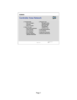
  • 1. Controller Area Network q Fundamentals q Physical Layer • How it all began... • Message Coding • Overview • Synchronization • Basic Concepts • Bit Timing / Bit q Data Link Layer Construction • Bus Access Arbitration • CAN Bus Lines • Frame Formats q CAN Implementations • Error Detection q User Benefits • Error Handling q Application Examples • Protocol Versions q Siemens CAN Devices (Standard /Extended) Siemens Microelectronics, Inc. October 98 CANPRES Version 2.0 Slide 1 Page 1
  • 2. How it all began... Air Engine Anti- Lighting Con- Control Lock dition Power Brakes Locks Dash- board Airbag Power Trans- Active Seats mission Suspen- Power Control sion Win- dows Siemens Microelectronics, Inc. October 98 CANPRES Version 2.0 Slide 2 •The development of CAN began when more and more electronic devices were implemented into modern motor vehicles. Examples of such devices include engine management systems, active suspension, ABS, gear control, lighting control, air conditioning, airbags and central locking. All this means more safety and more comfort for the driver and of course a reduction of fuel consumption and exhaust emissions. Page 2
  • 3. How it all began… (cont.) Air Engine Anti- Lighting Con- Control Lock dition Power Brakes Locks Dash- board Airbag Power Trans- Active Seats mission Suspen- Power Control sion Win- dows Siemens Microelectronics, Inc. October 98 CANPRES Version 2.0 Slide 3 • improve the behavior of the vehicle even further, it was necessary To for the different control systems (and their sensors) to exchange information. This was usually done by discrete interconnection of the different systems (i.e. point to point wiring). The requirement for information exchange has then grown to such an extent that a cable network with a length of up to several miles and many connectors was required. This produced growing problems concerning material cost, production time and reliability. Page 3
  • 4. How it all began… (cont.) Air Engine Anti- Lighting Con- Control Lock dition Power Brakes CAN Locks CAN CAN CAN CAN High Speed Dash- Low Speed CAN CAN board CAN CAN Airbag CAN CAN Power Seats CAN Trans- Active mission Suspen- Power Control sion Win- dows Siemens Microelectronics, Inc. October 98 CANPRES Version 2.0 Slide 4 •The solution to this problem was the connection of the control systems via a serial bus system. This bus had to fulfill some special requirements due to its usage in a vehicle. •With the use of CAN, point-to-point wiring is replaced by one serial bus connecting all control systems. This is accomplished by adding some CAN-specific hardware to each control unit that provides the "rules" or the protocol for transmitting and receiving information via the bus. Page 4
  • 5. Overview Specified by Robert Bosch Industrial CAN GmbH, Germany Spec ISO/OSI Automotive SAE à Distributed Controls CAL, CANopen (CiA), 140 7 Application Layer DeviceNet (ODVA), 120 100 SDS (Honeywell) ... 80 CAN } 60 Nodes 2 Data Link Layer 40 20 CAN 0 1997 1998 1999 2000 1 Physical Layer Siemens Microelectronics, Inc. October 98 CANPRES Version 2.0 Slide 5 •CAN or Controller Area Network is an advanced serial bus system that efficiently supports distributed control systems. It was initially developed for the use in motor vehicles by Robert Bosch GmbH, Germany, in the late 1980s, also holding the CAN license. •CAN is internationally standardized by the International Standardization Organization (ISO) and the Society of Automotive Engineers (SAE). •The CAN protocol uses the Data Link Layer and the Physical Layer in the ISO - OSI model. There are also a number of higher level protocols available for CAN. •CAN is most widely used in the automotive and industrial market segments. Typical applications for CAN are motor vehicles, utility vehicles, and industrial automation. Other applications for CAN are trains, medical equipment, building automation, household appliances, and office automation. Due to the high volume production in the automotive and industrial markets, low cost protocol devices are available. •There are about 20 million CAN nodes in use worldwide. By the year 2000 the number of nodes is estimated to be 140 million. •Examples of vehicle bus systems, other than CAN, are A-BUS from Volkswagen, VAN or Vehicle Area Network, from Peugeot and Renault, and J1850 from Chrysler, General Motors and Ford. •CAN is clearly the leading vehicle bus protocol in Europe. Page 5
  • 6. Basic Concepts n Multimaster n Easy CAN Concept connection/ Nodes disconnection n Number of of nodes nodes Node A Node n not limited by e.g. e.g. n Broadcast/ protocol ABS EMS Multicast capability n No node addressing, Message identifier CAN-Bus specifies (logical) contents & priority Siemens Microelectronics, Inc. October 98 CANPRES Version 2.0 Slide 6 •CAN is a multi-master bus with an open, linear structure with one logic bus line and equal nodes. The number of nodes is not limited by the protocol. • the CAN protocol, the bus nodes do not have a specific address. In Instead, the address information is contained in the identifiers of the transmitted messages, indicating the message content and the priority of the message. •The number of nodes may be changed dynamically without disturbing the communication of the other nodes. •Multicasting and Broadcasting is supported by CAN. Page 6
  • 7. Basic Concepts (cont.) Node A Node n n Sophisti- e.g. ABS e.g. EMS cated Error Application Detection / e.g. Handling e.g. Host-Controller 80C166 C167CR n NRZ Code or C515C + Bit Stuffing CAN-Controller 81C9x CAN for Synchroni- CAN-Transceiver zation CAN_H UDiff n Bus access 120 120 CAN-Bus Ohm Ohm via CAN_L EMI 40m / 130 ft CSMA/CD @ 1 Mbps w/ AMP Siemens Microelectronics, Inc. October 98 CANPRES Version 2.0 Slide 7 •CAN provides sophisticated error-detection and error handling mechanisms such as CRC check, and high immunity against electromagnetic interference. Erroneous messages are automatically retransmitted. Temporary errors are recovered. Permanent errors are followed by automatic switch-off of defective nodes. There is guaranteed system-wide data consistency. •The CAN protocol uses Non-Return-to-Zero or NRZ bit coding. For synchronization purposes, Bit Stuffing is used. •There is a high data transfer rate of 1000 kilobits per second at a maximum bus length of 40 meters or 130 feet when using a twisted wire pair which is the most common bus medium used for CAN. Message length is short with a maximum of 8 data bytes per message and there is a low latency between transmission request and start of transmission. •The bus access is handled via the advanced serial communications protocol Carrier Sense Multiple Access/Collision Detection with Non- Destructive Arbitration. This means that collision of messages is avoided by bitwise arbitration without loss of time. Page 7
  • 8. Basic Concepts - CAN Bus Characteristics - Wired-AND Two logic states “ = recessive 1” possible on the bus: “ = dominant 0” “ = recessive 1” “ = dominant 0” A B C BUS D D D D As soon as one node nodes transmits D D R D a dominant bit (zero): D R D D Bus is in the dominant state. D R R D R D D D R D R D Only if all nodes transmit R R D D recessive bits (ones): R R R R Bus is in the recessive state. Siemens Microelectronics, Inc. October 98 CANPRES Version 2.0 Slide 8 •There are two bus states, called "dominant" and "recessive". •The bus logic uses a "Wired-AND" mechanism, that is, "dominant bits" (equivalent to the logic level "Zero") overwrite the "recessive" bits (equivalent to the logic level "One" ). Page 8
  • 9. Basic Concepts - CAN Bus Characteristics - Wired-AND (cont.) 5V Bus State: recessive (High) CAN-Bus L L L (single logical bus line) R T R T R T recessive recessive recessive Node A Node B Node C Siemens Microelectronics, Inc. October 98 CANPRES Version 2.0 Slide 9 •Only if all nodes transmit recessive bits (ones), the Bus is in the recessive state. Page 9
  • 10. Basic Concepts - CAN Bus Characteristics - Wired-AND (cont.) 5V Bus State: dominant (Low) CAN-Bus H L L (single logical bus line) R T R T R T recessive recessive dominant Node A Node B Node C Siemens Microelectronics, Inc. October 98 CANPRES Version 2.0 Slide 10 • soon as one node transmits a dominant bit (zero), the bus is in the As dominant state. Page 10
  • 11. Bus Access and Arbitration: CSMA/CD w/ AMP Node X Node A Node B Node C Start Identifier Field Arbitration Bit Node A phase Node B Remainder Node C Transmit CAN Bus Request Node B loses Arbitration Node C loses Arbitration Siemens Microelectronics, Inc. October 98 CANPRES Version 2.0 Slide 11 •The CAN protocol handles bus accesses according to the concept called “ Carrier Sense Multiple Access with Arbitration on Message Priority” This arbitration concept avoids collisions of messages whose . transmission was started by more than one node simultaneously and makes sure the most important message is sent first without time loss. In the picture above you see the trace of the transmit pins of three bus nodes called A, B and C, and the resulting bus state according to the wired-AND principle. • two or more bus nodes start their transmission at the same time after If having found the bus to be idle, collision of the messages is avoided by bitwise arbitration. Each node sends the bits of its message identifier and monitors the bus level. • a certain time nodes A and C send a dominant identifier bit. Node B At sends a recessive identifier bit but reads back a dominant one. Node B loses bus arbitration and switches to receive mode. Some bits later node C loses arbitration against node A. This means that the message identifier of node A has a lower binary value and therefore a higher priority than the messages of nodes B and C. In this way, the bus node with the highest priority message wins arbitration without losing time by having to repeat the message. •Nodes B and C automatically try to repeat their transmission once the bus returns to the idle state. Node B loses against node C, so the message of node C is transmitted next, followed by node B’ message. s • is not permitted for different nodes to send messages with the same It identifier as arbitration could fail leading to collisions and errors. Page 11
  • 12. Frame Formats - Overview q Existing Frame Formats: Data Remote Error Frame Frame Frame Inter- Overload frame Frame Space Siemens Microelectronics, Inc. October 98 CANPRES Version 2.0 Slide 12 •These are the existing Frame formats which are now discussed in the following slides. Page 12
  • 13. Frame Formats - Data Frame Siemens Microelectronics, Inc. October 98 CANPRES Version 2.0 Slide 13 • "Data Frame" is generated by a CAN node when the node wishes to A transmit data. The Standard CAN Data Frame is shown above. The frame begins with a dominant Start Of Frame bit for hard synchronization of all nodes. •The Start of Frame bit is followed by the Arbitration Field consisting of 12 bits: The 11-bit Identifier, which reflects the contents and priority of the message, and the Remote Transmission Request bit. The Remote transmission request bit is used to distinguish a Data Frame (RTR = dominant) from a Remote Frame (RTR = recessive). •The next field is the Control Field, consisting of 6 bits. The first bit of this field is called the IDE bit (Identifier Extension) and is at dominant state to specify that the frame is a Standard Frame. The following bit is reserved and defined as a dominant bit. The remaining 4 bits of the Control Field are the Data Length Code (DLC) and specify the number of bytes of data contained in the message (0 - 8 bytes). •The data being sent follows in the Data Field which is of the length defined by the DLC above (0, 8, 16, ...., 56 or 64 bits). •The Cyclic Redundancy Field (CRC field) follows and is used to detect possible transmission errors. The CRC Field consists of a 15 bit CRC sequence, completed by the recessive CRC Delimiter bit. •The next field is the Acknowledge Field. During the ACK Slot bit the transmitting node sends out a recessive bit. Any node that has received an error free frame acknowledges the correct reception of the frame by sending back a dominant bit (regardless of whether the node is configured to accept that specific message or not). From this it can be seen that CAN belongs to the "in-bit-response" group of protocols. The recessive Acknowledge Delimiter completes the Acknowledge Slot and may not be overwritten by a dominant bit. • Page 13 Seven recessive bits (End of Frame) end the Data Frame.
  • 14. Frame Formats - Remote Frame Siemens Microelectronics, Inc. October 98 CANPRES Version 2.0 Slide 14 •Generally data transmission is performed on an autonomous basis with the data source node (e.g. a sensor) sending out a Data Frame. It is also possible, however, for a destination node to request the data from the source by sending a Remote Frame. •There are 2 differences between a Data Frame and a Remote Frame. Firstly the RTR-bit is transmitted as a dominant bit in the Data Frame and secondly in the Remote Frame there is no Data Field. In the very unlikely event of a Data Frame and a Remote Frame with the same identifier being transmitted at the same time, the Data Frame wins arbitration due to the dominant RTR bit following the identifier. In this way, the node that transmitted the Remote Frame receives the desired data immediately. Page 14
  • 15. Frame Formats - Remote Frame (cont.) q Remote Frame scenario How hot is the oil ? Node B Node A Remote Frame; Identifier 'oil_tmp' (oil temp.- 115 °C ! sensor) Data Frame; Identifier 'oil_tmp'; contains desired information ~~~~ 115°C ~~~~~ Siemens Microelectronics, Inc. October 98 CANPRES Version 2.0 Slide 15 • a node wishes to request the data from the source, it sends a If Remote Frame with an identifier that matches the identifier of the required Data Frame. The appropriate data source node will then send a Data Frame as a response to this remote request. Page 15
  • 16. Frame Formats - Error Frame q Active Error Frame: Used for error signaling Siemens Microelectronics, Inc. October 98 CANPRES Version 2.0 Slide 16 • Error Frame is generated by any node that detects a bus error. The Error An Frame consists of 2 fields, an Error Flag field followed by an Error Delimiter field. The Error Delimiter consists of 8 recessive bits and allows the bus nodes to restart bus communications cleanly after an error. There are, however, two forms of Error Flag fields. The form of the Error Flag field depends on the “error status”of the node that detects the error. • an “ If error-active” node detects a bus error then the node interrupts transmission of the current message by generating an “ active error flag” The . “active error flag” is composed of six consecutive dominant bits. This bit sequence actively violates the bit stuffing rule. All other stations recognize the resulting bit stuffing error and in turn generate Error Frames themselves. The Error Flag field therefore consists of between six and twelve consecutive dominant bits (generated by one or more nodes). The Error Delimiter field completes the Error Frame. After completion of the Error Frame bus activity returns to normal and the interrupted node attempts to resend the aborted message. • an “ If error passive” node detects a bus error then the node transmits an “passive Error Flag” followed, again, by the Error Delimiter field. The “ passive Error Flag” consists of six consecutive recessive bits, and therefore the Error Frame (for an “ error passive” node) consists of 14 recessive bits (i.e. no dominant bits). From this it follows that, unless the bus error is detected by the node that is actually transmitting (i.e. is the bus master), the transmission of an Error Frame by an “ error passive” node will not affect any other node on the network. If the bus master node generates an “ error passive flag” then this may cause other nodes to generate error frames due to the resulting bit stuffing violation. Page 16
  • 17. Frame Formats - Overload Frame q Overload Frame: Used to delay next CAN message Siemens Microelectronics, Inc. October 98 CANPRES Version 2.0 Slide 17 • Overload Frame has the same format as an “ An active” Error Frame. An Overload Frame, however can only be generated during Interframe Space. This is the way then an Overload Frame can be differentiated from an Error Frame (an Error Frame is sent during the transmission of a message). The Overload Frame consists of 2 fields, an Overload Flag followed by an Overload Delimiter. The Overload Flag consists of six dominant bits followed by Overload Flags generated by other nodes (as for “active error flag” again giving a maximum of twelve dominant bits). , The Overload Delimiter consists of eight recessive bits. An Overload Frame can be generated by a node if due to internal conditions the node is not yet able to start reception of the next message. A node may generate a maximum of 2 sequential Overload Frames to delay the start of the next message. Page 17
  • 18. Frame Formats - Interframe Space q Interframe Space: Separates a frame (of whatever type) from a following Data or Remote Frame. Siemens Microelectronics, Inc. October 98 CANPRES Version 2.0 Slide 18 •Interframe Space separates a preceeding frame (of whatever type) from a following Data or Remote Frame. Interframe space is composed of at least 3 recessive bits, these bits are termed the Intermission. This time is provided to allow nodes time for internal processing before the start of the next message frame. After the Intermission, for error active CAN nodes the bus line remains in the recessive state (Bus Idle) until the next transmission starts. •The Interframe Space has a slightly different format for error passive CAN nodes which were the transmitter of the previous message. In this case, these nodes have to wait another eight recessive bits called Suspend Transmission before the bus turns into bus idle for them after Intermission and they are allowed to send again. Due to this mechanism error active nodes have the chance to transmit their messages before the error passive nodes are allowed to start a transmission. Page 18
  • 19. Error Detection - Overview q Detected Errors: CRC Form Stuff Error Error Error ACK Bit Error Error Siemens Microelectronics, Inc. October 98 CANPRES Version 2.0 Slide 19 •The CAN protocol provides sophisticated error detection mechanisms discussed in the following slides. Page 19
  • 20. Error Detection - Cyclic Redundancy Check q Calculated and received CRC Checksum must match... Node A Node B Calculated Calculated Idle CRC Checksum: CRC Checksum: Idle Receive 1234h 1234h Receive Transmit Transmit Transmitted Received CRC Checksum: CRC Checksum: 1234h 1234h match CAN_H Data Frame CAN_L CRC Sequence Siemens Microelectronics, Inc. October 98 CANPRES Version 2.0 Slide 20 •With the Cyclic Redundancy Check, the transmitter calculates a check sum for the bit sequence from the start of frame bit until the end of the Data Field. •This CRC sequence is transmitted in the CRC Field of the CAN frame. •The receiving node also calculates the CRC sequence using the same formula and performs a comparison to the received sequence. Page 20
  • 21. Error Detection - Cyclic Redundancy Check (cont.) q … otherwise Frame was not received correctly (CRC Error) Node A Node B Calculated Calculated Idle CRC Checksum: CRC Checksum: Idle Receive 1234h 1235h Receive Transmit Transmit Transmitted Received CRC Checksum: CRC Checksum: 1234h 1234h mismatch CAN_H Error Frame CAN_L Siemens Microelectronics, Inc. October 98 CANPRES Version 2.0 Slide 21 • node B detects a mismatch between the calculated and the received If CRC sequence , then a CRC error has occurred. •Node B discards the message and transmits an Error Frame to request retransmission of the garbled frame. Page 21
  • 22. Error Detection - Acknowledge Ack. Field q A frame must be acknow- Node A Recessive ledged by Idle at least one TX other node Receive Dominant Transmit (otherwise Node B Recessive ACK-Error) Idle Receive TX Dominant Transmit Recessive CAN Bus Idle Active Dominant Ack. Delimiter Acknowledge Slot Siemens Microelectronics, Inc. October 98 CANPRES Version 2.0 Slide 22 •With the Acknowledge Check the transmitter checks in the Acknowledge Field of a message to determine if the Acknowledge Slot, which is sent out as a recessive bit, contains a dominant bit. • this is the case, at least one other node, (here node B) has received If the frame correctly. • not, an Acknowledge Error has occured and the message has to be If repeated. No Error Frame is generated, though. Page 22
  • 23. Error Detection - Frame Check q No dominant bits allowed in CRC Delimiter, ACK Delimiter, End of Frame, 1 1 7 3 Intermission (Form Error) Siemens Microelectronics, Inc. October 98 CANPRES Version 2.0 Slide 23 •Another error detection mechanism is the Frame Check. If a transmitter detects a dominant bit in one of the four segments: CRC Delimiter, Acknowledge Delimiter, End of Frame or Interframe Space then a Form Error has occurred and an Error Frame is generated. The message will then be repeated. Page 23
  • 24. Error Detection - Bit Monitoring q A transmitted bit must be correctly read back from the CAN bus (otherwise Bit Error) q Dominant bits may 11 1 1 overwrite recessive bits only in the Arbitration Field and in the Acknowledge Slot Siemens Microelectronics, Inc. October 98 CANPRES Version 2.0 Slide 24 • nodes perform Bit Monitoring: A Bit Error occurs if a transmitter All sends a dominant bit but detects a recessive bit on the bus line or, sends a recessive bit but detects a dominant bit on the bus line. • Error Frame is generated and the message is repeated. An •When a dominant bit is detected instead of a recessive bit, no error occurs during the Arbitration Field or the Acknowledge Slot because these fields must be able to be overwritten by a dominant bit in order to achieve arbitration and acknowledge functionality. Page 24
  • 25. Error Detection - Bit Stuffing Check q 6 consecutive bits with same polarity are not allowed between Start Of Frame and CRC Delimiter (otherwise Bit Stuffing Error) Siemens Microelectronics, Inc. October 98 CANPRES Version 2.0 Slide 25 • six consecutive bits with the same polarity are detected between If Start of Frame and the CRC Delimiter, the bit stuffing rule has been violated. • stuff error occurs and an Error Frame is generated. The message is A then repeated. Page 25
  • 26. Error Handling Node A Node B Node C Error Error Error reco- reco- detected gnized gnize Idle d Idle Idle Receive Error Frame Receive Receive Transmit Transmit Transmit CAN_H Data Frame CAN_L Siemens Microelectronics, Inc. October 98 CANPRES Version 2.0 Slide 26 •Detected errors are made public to all other nodes via Error Frames. •The transmission of the erroneous message is aborted and the frame is repeated as soon as possible. Page 26
  • 27. Error Handling (cont.) REC<=127 REC>127 and or TEC>255 TEC<=127 TEC>127 Error Error Bus Reset active passive off Re-Initialization only Siemens Microelectronics, Inc. October 98 CANPRES Version 2.0 Slide 27 •Each CAN node is in one of three error states "error active", "error passive" or "bus off" according to the value of their internal error counters. •The error-active state is the usual state after reset. The bus node can then receive and transmit messages and transmit active Error Frames (made of dominant bits) without any restrictions. During CAN communication, the error counters are updated according to quite complex rules. For each error on reception or transmission, the error counters are incremented by a certain value. For each successful transaction, the error counters are decremented by a certain value. The error active state is valid as long as both error counters are smaller than or equal to 127. • either the receive or the transmit error counter has reached the value of If 128, the node switches to the error-passive state. In the error-passive state, messages can still be received and transmitted, although, after transmission of a message the node must suspend transmission. It must wait 8 bit times longer than error-active nodes before it may transmit another message. In terms of error signaling, only passive Error Frames (made of recessive bits) may be transmitted by an error-passive node. • both error counters go below 128 again due to successful bus If communication, the node switches back to the error-active state. •One feature of the CAN protocol is that faulty nodes withdraw from the bus automatically. The bus-off state is entered if the transmit error counter exceeds the value of 255. All bus activities are stopped which makes it temporarily impossible for the station to participate in the bus communication. During this state, messages can be neither received nor transmitted. To return to the error active state and to reset the error counter values, the CAN node has to be reinitialized. Page 27
  • 28. Undetected Errors - an example q 2000 h/year q 500 kbps q 25% bus load q 1 undetected error every 1000 years Siemens Microelectronics, Inc. October 98 CANPRES Version 2.0 Slide 28 •To understand the error detection capabilities of CAN, imagine a vehicle equipped with CAN running 2000 hours per year at a CAN bus speed of 500 kbps with 25% bus load. •This will result in 1 undetected error every 1000 years. Page 28
  • 29. CAN Protocol Versions q Two CAN protocol versions available: • V2.0A (Standard) - 11 bit Message ID’ - 2048 ID’ available s s Start of Identifier Control Data Field CRC ACK End Frame 11 bits Field (0..8 Bytes) Field Field of Frame • V2.0B (Extended) - 29 bit Message ID’ - s more than 536 Million ID’ available s Start of Identifier Control Data Field CRC ACK End Frame 29 bits Field (0..8 Bytes) Field Field of Frame Siemens Microelectronics, Inc. October 98 CANPRES Version 2.0 Slide 29 •The original CAN specifications (Versions 1.0, 1.2 and 2.0A) specify an 11 bit message identifier. This is known as "Standard CAN". •Those Data Frames and Remote Frames, which contain an 11-bit identifier are therefore called Standard Frames. •With these frames, 211 (=2048) different messages can be identified (identifiers 0-2047). •However, the 16 messages with the lowest priority (2032-2047) are reserved. •Specification V2.0A has since been updated (to version 2.0B) to remove this possible message number limitation and meet the SAE J1939 standard for the use of CAN in trucks. •Version 2.0B CAN is referred to as "Extended CAN". •Extended Frames, according to CAN specification V2.0 part B, contain a 29-bit identifier which allows 229 (over 536 Million) message identifiers. •The 29-bit identifier is made up of the 11-bit identifier ("Base ID") and the 18-bit Extended Identifier ("ID Extension"). •CAN specification Version 2.0B still allows message identifier lengths of 11 bits to be used. Page 29
  • 30. CAN Protocol Versions (cont.) q Three Types of CAN Modules available (all handle 11 bit ID’ s) • 2.0A - Considers 29 bit ID as an error • 2.0B Passive - Ignores 29 bit ID messages • 2.0B Active - Handles both 11 and 29 bit ID Messages V2.0B Active CAN Module V2.0B Passive CAN Module V2.0A CAN Module Siemens Microelectronics, Inc. October 98 CANPRES Version 2.0 Slide 30 •There are three different types of CAN modules available. 2.0A - Considers 29 bit ID as an error 2.0B Passive - Ignores 29 bit ID messages 2.0B Active - Handles both 11 and 29 bit ID Messages Page 30
  • 31. CAN Protocol Versions (cont.) Frame with Frame with 11 bit ID 29 bit ID V2.0B Active Tx/Rx OK Tx/Rx OK CAN Module V2.0B Passive Tx/Rx OK Tolerated CAN Module V2.0A CAN Tx/Rx OK Bus ERROR Module q Care must be taken when mixing protocol versions Siemens Microelectronics, Inc. October 98 CANPRES Version 2.0 Slide 31 •CAN modules specified after CAN V2.0 part A are only able to transmit and receive Standard Frames according to the Standard CAN protocol. •Messages using the 29-bit identifier sent to a Standard CAN module cause errors. • a device is specified after CAN V2.0 part B, there's one more If distinction. Modules named "V2.0B Passive" can only transmit and receive Standard Frames but tolerate Extended Frames without generating Error Frames. •"V2.0B Active" devices are able to transmit and receive both Standard and Extended Frames. •Siemens offers V2.0B Active and V2.0B Passive devices. Page 31
  • 32. Message Coding q Message Coding: NRZ-Code Signal to Signal to transmit a “0” transmit a “1” HIGH HIGH LOW LOW “1” “0” 0 1 0 ... Siemens Microelectronics, Inc. October 98 CANPRES Version 2.0 Slide 32 •The CAN protocol uses Non-Return-to-Zero or NRZ bit coding. This means that the signal is constant for one whole bit time and only one time segment is needed to represent one bit. •Usually, but not always, a "zero" corresponds to a dominant bit, placing the bus in the dominant state, and a "one" corresponds to a recessive bit, placing the bus in the recessive state. Page 32
  • 33. Bit Stuffing q Bit Stuffing ensures sufficient Recessive to Dominant edges • Stuff Bit inserted after 5 consecutive bits at the same state • Stuff Bit is inverse of previous bit 1 2 3 4 5 67 8 ... 1 2 3 4 5 67 8 ... data stream No. of consecutive bits with Stuff Stuff Stuff same polarity Bit Bit Bit bit stream 1 1 1 2 3 4 5 1 2 3... 12345 12345 1 Siemens Microelectronics, Inc. October 98 CANPRES Version 2.0 Slide 33 •One characteristic of Non-Return-to-Zero code is that the signal provides no edges that can be used for resynchronization when transmitting a large number of consecutive bits with the same polarity. •Therefore Bit stuffing is used to ensure synchronization of all bus nodes. •This means that during the transmission of a message, a maximum of five consecutive bits may have the same polarity. •Whenever five consecutive bits of the same polarity have been transmitted, the transmitter will insert one additional bit of the opposite polarity into the bit stream before transmitting further bits. •The receiver also checks the number of bits with the same polarity and removes the stuff bits again from the bit stream. This is called "destuffing". Page 33
  • 34. Bus Synchronization q Hard Synchronization at Start Of Frame bit Intermission / SOF ID10 ID9 ID8 ID7 Idle All nodes synchronize on leading edge of SOF bit (Hard Synchronization) q Re-Synchronization on each Recessive to Dominant edge Re- Re- Re- Re- synch synch synch synch Siemens Microelectronics, Inc. October 98 CANPRES Version 2.0 Slide 34 • contrast to many other field buses, CAN handles message transfers In synchronously. • nodes are synchronized at the beginning of each message with the All first falling edge of a frame which belongs to the Start Of Frame bit. •This is called Hard Synchronization. • ensure correct sampling up to the last bit, the CAN nodes need to To re-synchronize throughout the entire frame. This is done on each recessive to dominant edge. Page 34
  • 35. Bit Construction q 4 Segments, 8-25 Time Quanta (TQ) per bit time q Time Quanta generated by programmable divide of Oscillator q CAN Baud Rate (= 1 / Bit Time) programmed by selection of appropriate TQ length + appropriate number of TQ per bit CAN frame 1 Bit Time 1 2 3 4 1 Time Quantum Siemens Microelectronics, Inc. October 98 CANPRES Version 2.0 Slide 35 •One CAN bit time (or one high or low pulse of the NRZ code) is specified as four non-overlapping time segments. •Each segment is constructed from an integer multiple of the Time Quantum. •The Time Quantum or TQ is the smallest discrete timing resolution used by a CAN node. • length is generated by a programmable divide of the CAN node's Its oscillator frequency. •There is a minimum of 8 and a maximum of 25 Time Quanta per bit. •The bit time, and therefore the bit rate, is selected by programming the width of the Time Quantum and the number of Time Quanta in the various segments. Page 35
  • 36. Synchronization Segment 1 Bit Time 1 Transmit Synchronization Segment Point n Next bit is output at start of this segment (Transmit only) n Bus State change (if any) expected to occur within this segment by the receivers n Fixed length of 1 Time Quantum Siemens Microelectronics, Inc. October 98 CANPRES Version 2.0 Slide 36 •The first segment within a CAN bit is called the Synchronization Segment and is used to synchronize the various bus nodes. •On transmission, at the start of this segment, the current bit level is output. • there is a bit state change between the previous bit and the current If bit, then the bus state change is expected to occur within this segment by the receiving nodes. •The length of this segment is always 1 Time Quantum. Page 36
  • 37. Propagation Segment 1 Bit Time 2 Propagation Time Segment n Allows for signal propagation (across network and through nodes) n Programmable length (1..8 Time Quanta) Siemens Microelectronics, Inc. October 98 CANPRES Version 2.0 Slide 37 •The Propagation Time Segment is used to compensate for signal delays across the network. •This is necessary to compensate for signal propagation delays on the bus line and through the electronic interface circuits of the bus nodes. •This segment may be 1 to 8 Time Quanta long. Page 37
  • 38. Phase Buffer Segment 1 1 Bit Time 3 Phase Buffer Sample Segment 1 Point n Allows for lengthening of bit during Re-synchronization n Bus state is sampled at the end of this segment n Programmable length (1..8 Time Quanta) Siemens Microelectronics, Inc. October 98 CANPRES Version 2.0 Slide 38 •Phase Buffer Segment 1 is used to compensate for edge phase errors. This segment may be between 1 to 8 Time Quanta long and may be lengthened during resynchronization. •The sample point is the point of time at which the bus level is read and interpreted as the value of the respective bit. Its location is at the end of Phase Buffer Segment 1 (between the two Phase Buffer Segments). Page 38
  • 39. Phase Buffer Segment 2 1 Bit Time 4 Sample Phase Buffer Point Segment 2 n Allows for shortening of bit during Re-synchronization n Programmable length (1..8 Time Quanta) Siemens Microelectronics, Inc. October 98 CANPRES Version 2.0 Slide 39 •Phase Buffer Segment 2 is also used to compensate for edge phase errors. This segment may be shortened during resynchronization. •Phase Buffer Segment 2 may be between 1 to 8 Time Quanta long, but the length has to be at least as long as the information processing time (see below) and may not be more than the length of Phase Buffer Segment 1. •The information processing time begins with the sample point and is reserved for calculation of the subsequent bit level. It is less than or equal to two Time Quanta long. Page 39
  • 40. Bit Lengthening Needed Sample tq Point Phase Phase Next Sync- Propagation Buffer Buffer Sync- Segment Time Segment Segment 1 Segment 2 Segment Transmitter (slower) next edge for Re-synchronization delayed by 1 TQ ... Phase Phase Next Sync- Propagation Buffer Buffer Sync- Segment Time Segment Segment 1 Segment 2 Segment Receiver (faster) expected Sample Point Siemens Microelectronics, Inc. October 98 CANPRES Version 2.0 Slide 40 • a result of resynchronization, Phase Buffer Segment 1 may be As lengthened or Phase Buffer Segment 2 may be shortened to compensate for oscillator tolerances within the different CAN nodes. • for example, the transmitter oscillator is slower than the receiver If, oscillator, the next falling edge used for resynchronization may be delayed. So Phase Buffer Segment 1 is lengthened... Page 40
  • 41. Bit Lengthening (cont.) Needed Sample tq Point Phase Phase Next Sync- Propagation Buffer Buffer Sync- Transmitter Segment Time Segment Segment 1 Segment 2 Segment (slower) Phase Buffer Segment 1 lengthened by 1 TQ Phase Phase Next Sync- Propagation Buffer Buffer Sync- Segment Time Segment Segment 1 Segment 2 Segment Receiver (faster) New Sample Point Siemens Microelectronics, Inc. October 98 CANPRES Version 2.0 Slide 41 • in order to adjust the sample point and the end of the bit time. … Page 41
  • 42. Bit Shortening bit n bit n+1 Needed Sample Point for bit n+1 Phase Buffer Phase Buffer Sync- Propagation Phase Buffer Phase Buffer Sync- Segment 1 Segment 2 Segment Time Segment Segment 1 Segment 2 Segment Transmitter (faster) next edge for Re-synchronization is 1 TQ too early... Receiver Phase Buffer Phase Buffer Sync- Propagation Phase Buffer Phase Buffer Sync- (slower) Segment 1 Segment 2 Segment Time Segment Segment 1 Segment 2 Segment tq expected Sample Point for bit n+1 Siemens Microelectronics, Inc. October 98 CANPRES Version 2.0 Slide 42 • on the other hand, the transmitter oscillator is faster than the If, receiver oscillator, the next falling edge used for resynchronization may be too early. So Phase Buffer Segment 2 in bit N is shortened... Page 42
  • 43. Bit Shortening (cont.) bit n bit n+1 needed Sample Point for bit n+1 Phase Buffer Phase Buffer Sync- Propagation Phase Buffer Phase Buffer Sync- Segment 1 Segment 2 Segment Time Segment Segment 1 Segment 2 Segment Transmitter (faster) Phase Buffer segment 2 in bit n is shortened by 1 TQ Phase Receiver Buffer Phase Buffer Segment Sync- Propagation Phase Buffer Phase Buffer Sync- (slower) Segment 1 2 Segment Time Segment Segment 1 Segment 2 Segment new Sample Point for bit n+1 Siemens Microelectronics, Inc. October 98 CANPRES Version 2.0 Slide 43 • in order to adjust the sample point for bit N+1 and the end of the bit … time Page 43
  • 44. Synchronization Jump Width q Amount by which bit length can be adjusted during Re-synch is defined as Synchronization Jump Width • No of TQ by which Phase Buffer Segment 1 can be lengthened • No of TQ by which Phase Buffer Segment 2 can be shortened q Programmability of Synchronization Jump Width is mandatory • Minimum of 1 Tq, maximum of 4 Tq Siemens Microelectronics, Inc. October 98 CANPRES Version 2.0 Slide 44 •The limit to the amount of lengthening or shortening of the phase buffer segments is set by the Resynchronization Jump Width. •The Resynchronization Jump Width may be between 1 and 4 Time Quanta, but it may not be longer than Phase Buffer Segment 2. Page 44
  • 45. Bit Timing q For ease of programming many CAN Modules combine Propagation Time Segment and Phase Buffer Segment 1 (i.e. they only use 3 segments) 1 Bit Time Propagation Phase Buffer Time Segment Segment 1 + = Timing Segment 1 Timing Segment 2 Siemens Microelectronics, Inc. October 98 CANPRES Version 2.0 Slide 45 •For many CAN module implementations, the Propagation Time Segment and Phase Buffer Segment 1 are combined, for ease of programming, into one segment often called Timing Segment 1. •Phase Buffer Segment 2 is then known as Timing Segment 2. Page 45
  • 46. Why Program the Sample Position ? q Early sampling decreases the sensitivity to oscillator tolerances q Lower cost oscillators (e.g. ceramic resonators) can be used 1 Bit Time Maximum Synchronization Jump Width (4) Transmit Early Point Sample Point Siemens Microelectronics, Inc. October 98 CANPRES Version 2.0 Slide 46 •Programming of the sample point allows "tuning" of the characteristics to suit the bus. •Early sampling allows more Time Quanta in the Phase Buffer Segment 2 so the Synchronization Jump Width can be programmed to its maximum of 4 Time Quanta. •This maximum capacity to shorten or lengthen the bit time decreases the sensitivity to node oscillator tolerances, so that lower cost oscillators such as ceramic resonators may be used. Page 46
  • 47. Why Program the Sample Position ? (cont.) q Late sampling allows maximum signal propagation time q Maximum bus length / Poor bus topologies can be handled 1 Bit Time Time for signal propagation Transmit Late Point Sample Point Siemens Microelectronics, Inc. October 98 CANPRES Version 2.0 Slide 47 •Late sampling allows more Time Quanta in the Propagation Time Segment which allows a poorer bus topology and maximum bus length. Page 47
  • 48. Relation between Baud Rate and Bus Length q Up to 1Mbit / sec @40m bus length (130 feet) 1000 Bus lines 500 assumed to be 200 an electrical medium Bit Rate 100 (e.g.twisted [kbps] 50 pair) 20 10 5 0 10 40 100 200 1000 10,000 CAN Bus Length [m] Siemens Microelectronics, Inc. October 98 CANPRES Version 2.0 Slide 48 •The maximum CAN bus speed is 1 MBaud, which can be achieved with a bus length of up to 40 meters when using a twisted wire pair. •For bus lengths longer than 40 meters the bus speed must be reduced. • 1000 meter bus can still be realised with a 50 KBaud bus speed. A •For a bus length above 1000 meters special drivers should be used. Page 48
  • 49. CAN Bus Line Characteristics - Wired-AND 5V Two logic states: CAN-Bus “ = recessive 1” (single logical “ = dominant 0” Bus State: dominant bus line) A B C BUS D D D D D D R D D R D D R T R T R T recessive recessive dominant D R R D R D D D R D R D R R D D R R R R Node A Node B Node C Siemens Microelectronics, Inc. October 98 CANPRES Version 2.0 Slide 49 • CAN is serial bus system with one logical bus line. It has an open, linear bus structure with equal bus nodes. The number of nodes on the bus is not restricted by the protocol and may be changed dynamically without disturbing the communication of other nodes. This allows easy connection and disconnection of bus nodes, e.g. for addition of system function, error recovery or bus monitoring. • The CAN bus line has two logic states: a “ recessive” state and a “dominant” state. The actual bus state is “ wire-AND” of all node states. This means, that recessive bits (mostly, but not necessarily equivalent to the logic level "1") are overwritten by dominant bits (mostly logic level "0"). As long as no bus node is sending a dominant bit, the bus line is in the recessive state, but a dominant bit from any bus node generates the dominant bus state. Page 49
  • 50. ISO Physical Layer q Usual ISO Physical Layer :- • Bus wires twisted pair, 120R Termination at each end • 2 wires driven with differential signal (CAN_H, CAN_L) CAN_Txd Optical Fiber Optical CAN_Rxd Transmitter Receiver C16xC.. C5xxC.. CAN_Txd Physical CAN Bus CAN_Rxd (Differential, e.g Twisted Pair) CAN_Txd Differential CAN_Rxd Bus Driver Siemens Microelectronics, Inc. October 98 CANPRES Version 2.0 Slide 50 •Therefore, for the CAN bus line, a medium must be chosen that is able to transmit the two possible bit states “ dominant” and “recessive” One . of the most common and cheapest ways is to use a twisted wire pair. The bus lines are then called "CAN_H" and "CAN_L". The two bus lines CAN_H and CAN_L are driven by the nodes with a differential signal. The twisted wire pair is terminated by terminating resistors at each end of the bus line, typically 120 Ohms. •But also an optical medium would be possible for CAN. In this case, the recessive state would be represented by the signal “ light off” the , dominant state by the signal “ light on”. Page 50
  • 51. CAN and EMI q CAN is insensitive to electromagnetic interference V Node A Node B Node C CAN_H U diff CAN_L t CAN_H 120 120 Ohm Ohm CAN_L CAN-Bus EMI Siemens Microelectronics, Inc. October 98 CANPRES Version 2.0 Slide 51 •Due to the differential nature of transmission CAN is insensitive to electromagnetic interference, because both bus lines are affected in the same way which leaves the differential signal unaffected. •To reduce the sensitivity against electromagnetic interference even more, the bus lines can additionally be shielded. This also reduces the electromagnetic emission of the bus itself, especially at high baudrates. Page 51
  • 52. Standardization Issues CAN High Speed bit rate / kbps CAN ISO-IS Low 11898 Speed ISO-IS 1000 11519-2 Engine Class C management, 125 Gearbox, ABS Class B dashboard, diagnostics 10 Class A body control Real-time capability Siemens Microelectronics, Inc. October 98 CANPRES Version 2.0 Slide 52 •Vehicle bus system applications can be separated in three different categories according to their real-time capabilities. •Class A for a low speed bus with bit rates up to 10 kbps, e.g for body control applications, •Class B for a low speed bus with bit rates from 10 kbps to 125 kbps, e.g. for dashboard and diagnostics, •Class C for a high speed bus with bit rates from 125 kbps to 1 Mbps for real time applications like engine management, Gearbox, ABS etc. •For the use of CAN in vehicles two standards have been defined for the bus interface: •CAN High Speed according to ISO-IS 11898 for bit rates between 125 kbps and 1 Mbps •CAN Low Speed according to ISO-IS 11519-2 for bit rates up to 125 kbps Page 52
  • 53. Physical Layer according to ISO-IS 11898 CAN Node 1 Node 32 High Speed ISO-IS 11898 … … ... CAN Bus CAN Bus Driver Driver 40 m / 130 ft 0.3 m / 1 ft CAN_H @ 1 Mbps @ 1 Mbps 120 120 Ohm Ohm CAN_L Siemens Microelectronics, Inc. October 98 CANPRES Version 2.0 Slide 53 •This is the structure of a Controller Area Network according to ISO-IS 11898. The bus lines may be up to 40 m (130 ft) long at the maximum speed of 1 Mbaud and are terminated by termination resistors of 120 Ohms. The bus lines may be longer when decreasing the baud rate. Up to 30 nodes can be connected with CAN drivers according to this standard. For the connection of more nodes, stronger drivers or repeaters have to be used. To avoid reflexions the connection from the bus lines to the nodes should not exceed 0.3 m (1 ft) at 1 Mbps. Page 53
  • 54. Bus Levels according to ISO-IS 11898 CAN High V Recessive Dominan Recessive Speed t ISO-IS 5 11898 4 UCAN_H 3.5 V 3 U diff 2.5 V 2 1.5 V 1 UCAN_L Siemens Microelectronics, Inc. October 98 CANPRES Version 2.0 Slide 54 •These are the bus levels according to ISO-IS 11898. A recessive bit is represented by both CAN bus lines driven to a level of about 2.5 V so that the differential voltage between CAN_H and CAN_L is around 0 V. • dominant bit is represented by CAN_H going to about 3.5 V and A CAN_L going to about 1.5 V. This results in a differential voltage for a dominant bit of about 2V. Page 54
  • 55. CAN bus connectors according to CiA-DS 102-1 2: CAN_L 3: 0V (ground) CiA bus line 4: reserved DS 102-1 1: reserved 1 2 3 4 5 5: reserved 6: 0V 9: V+ (opt. (ground) 6 7 8 9 power supply) 7: CAN_H 8: reserved bus line Siemens Microelectronics, Inc. October 98 CANPRES Version 2.0 Slide 55 • be able to use CAN as a industrial field bus in an open system the To CAN in Automation user’ group CiA created a standard called CiA DS s 102-1 which is based on the 11898-standard. One important issue in this standard is the proposal to use a 9-pole SUB-D connector for the connection of nodes to the CAN bus lines. •The bus signals CAN_H and CAN_L are available on pins 7 and 2. The other pins serve as power or ground wires or are reserved for future extensions of the standard. Page 55
  • 56. Typical CAN Implementations Node A Node B Application e.g. ABS e.g. EMS e.g. e.g. Host-Controller 80C166 C167CR or C515C CAN-Controller 81C9x CAN (more nodes) CAN-Transceiver CAN-Bus Siemens Microelectronics, Inc. October 98 CANPRES Version 2.0 Slide 56 • typical CAN node used to control a certain application consists of A different devices. •The application itself is controlled by a microcontroller, e.g. the Siemens SAB 80C166. •To be able to participate in the CAN communication, the microcontroller has to be connected to a CAN protocol controller, e.g. the Siemens stand-alone Full-CAN controller 81C90/91. • meet the requirements of e.g. the ISO 11898 CAN standard, a To CAN transceiver chip is used to connect the node to the CAN bus lines. • more sophisticated way is to use a microcontroller which already has A a CAN protocol controller on-chip, e.g. one of the Siemens 8051- compatible 8-bit microcontrollers from the C500 family like the C505C or the C515C. For applications which need higher performance, one of the 16-bit C166-family members with integrated CAN module could be used, e.g. the C164CI or the C167CR. This saves costs as the printed circuit board space is used more efficiently and the user does not have to worry about setting up the communication between the microcontroller and the CAN controller. Page 56
  • 57. Basic CAN controller Status/Control Registers L low high Host CPU CAN CAN Bus Interface Bus Protocol Host CPU load Controller Transmit Inter- Buffer face Tx Rx Acceptance Receive Filtering Buffer(s) q Use in CANs with very low baudrates and/or very few messages only Siemens Microelectronics, Inc. October 98 CANPRES Version 2.0 Slide 57 •There is one more CAN characteristic concerning the interface between the CAN protocol controller and the host CPU, dividing CAN chips into "Basic-CAN" and "Full-CAN" devices. This has nothing to do with the used protocol Version though, which makes it possible to use both Basic-CAN and Full-CAN devices in the same network. • the Basic-CAN devices, only basic functions concerning the filtering In and management of CAN messages are implemented in hardware. A Basic-CAN controller typically provides one transmit buffer for outgoing messages and one or two receive buffers for incoming messages. In the receive path, an acceptance filtering is available which allows that only certain CAN identifiers are stored in the receive buffer. •Because there are only two buffers for the reception of messages the host controller is quite busy reading and storing the incoming messages before they get overwritten by the following ones which results in a quite high CPU load. Also the answering of Remote Frames with the corresponding Data Frame has to be handled by the host controller. Therefore Basic-CAN devices should only be used at low baudrates and low bus loads with only a few different messages. Page 57
  • 58. Full CAN controller Status/Control CAN CAN Registers Bus Bus Interface Protocol Controller Message Object 1 Host Inter- J face low high Acceptance Message Filtering Object 2 CPU load ... Host CPU Message Object n Receive Buffer(s) Siemens Microelectronics, Inc. October 98 CANPRES Version 2.0 Slide 58 •Full-CAN devices provide the whole hardware for convenient acceptance filtering and message management. For each message to be transmitted or received these devices contain one so called message object in which all information regarding the message (e.g. identifier, data bytes etc.) are stored. During the initialisation of the device, the host CPU defines which messages are to be sent and which are to be received. Only if the CAN controller receives a message whose identifier matches with one of the identifiers of the programmed (receive-) message objects the message is stored and the host CPU is informed by interrupt. Another advantage is that incoming Remote Frames can be answered automatically by the Full-CAN controller with the corresponding Data Frame. In this way, the CPU load is strongly reduced compared to the Basic-CAN solution. Using Full CAN devices, high baudrates and high bus loads with many messages can be handled. •Many Full-CAN controller provide a "Basic-CAN-Feature": One of their message objects behaves like a Basic-CAN Receive Buffer, i.e. it can be programmed in a way that every message is stored there that does not match with one of the other message objects. This can be very helpful in applications where the number of message objects is not enough to receive all desired messages. Page 58
  • 59. Complete CAN Capability – Products at Each Price-Performance Point price C167CR Flash ROM C164CI OTP ROM C515C OTP ROM C505C OTP ROM 81C91 81C90 performance Siemens Microelectronics, Inc. October 98 CANPRES Version 2.0 Slide 59 User Benefits q CAN is low cost • Serial bus with two wires: good price/performance ratio • Low cost protocol devices available driven by high volume production in the automotive and industrial markets q CAN is reliable • Sophisticated error detection and error handling mechanisms results in high reliability transmission • Example: 500 kbit/s, 25% bus load, 2000 hours per year: One undetected error every 1000 years • Erroneous messages are detected and repeated • Every bus node is informed about an error • High immunity to Electromagnetic Interference Siemens Microelectronics, Inc. October 98 CANPRES Version 2.0 Slide 60 1