SlideShare uma empresa Scribd logo
1 de 35
Baixar para ler offline
1
Program No. 1
Aim: Write a VHDL program to implement a 3:8 decoder.
Truth Table:
A B C EN D0 D1 D2 D3 D4 D5 D6 D7
0 0 0 1 1 0 0 0 0 0 0 0
1 0 0 1 0 0 0 0 1 0 0 1
0 1 0 1 0 0 1 0 0 0 0 0
1 1 0 1 0 0 0 0 0 0 1 0
0 0 1 1 1 0 0 0 0 0 0 0
1 0 1 0 0 0 0 0 0 0 0 0
0 1 1 0 0 0 0 0 0 0 0 0
1 1 1 1 0 0 0 0 0 0 0 1
0 0 0 1 1 0 0 0 0 0 0 0
Program:
library IEEE;
use IEEE.STD_LOGIC_1164.ALL;
use IEEE.STD_LOGIC_ARITH.ALL;
use IEEE.STD_LOGIC_UNSIGNED.ALL;
---- Uncomment the following library declaration if instantiating
---- any Xilinx primitives in this code.
--library UNISIM;
--use UNISIM.VComponents.all;
entity decoder is
Port ( A : in STD_LOGIC;
B : in STD_LOGIC;
C : in STD_LOGIC;
EN : in STD_LOGIC;
D : out STD_LOGIC_VECTOR (0 to 7));
end decoder;
2
architecture Behavioral of decoder is
begin
process(A,B,C,EN)
variable ABAR,BBAR,CBAR:STD_LOGIC;
begin
ABAR :=NOT A;
BBAR :=NOT B;
CBAR :=NOT C;
if EN='1' then
D(0)<= ABAR AND BBAR AND CBAR;
D(1)<= ABAR AND BBAR AND C;
D(2)<= ABAR AND B AND CBAR;
D(3)<= ABAR AND B AND C;
D(4)<= A AND BBAR AND CBAR;
D(5)<= A AND BBAR AND C;
D(6)<= A AND B AND CBAR;
D(7)<= A AND B AND C;
else
D <= "00000000";
end if;
end process;
end Behavioral;
3
RTL Logic:
Output Waveform:
Result: VHDL Program of a 3 :8 decoder has been implemented
4
Program No. 2
Aim: Write a VHDL program to implement an 8:1 multiplexer.
Truth Table:
S0 S1 S2 A0 A1 A2 A3 A4 A5 A6 A7 Z
0 0 0 0 0 0 0 0 0 0 0 0
1 0 0 0 0 0 0 0 0 0 1 0
0 1 0 1 0 0 0 1 0 1 0 0
1 1 0 1 1 1 1 1 1 1 0 1
0 0 1 1 0 1 1 0 1 1 1 0
1 0 1 0 0 1 0 1 1 1 0 1
0 1 1 1 1 1 0 1 0 1 0 0
1 1 1 1 0 1 1 1 0 0 1 1
0 0 0 1 0 1 1 0 1 0 1 1
Program:-
library IEEE;
use IEEE.STD_LOGIC_1164.ALL;
use IEEE.STD_LOGIC_ARITH.ALL;
use IEEE.STD_LOGIC_UNSIGNED.ALL;
---- Uncomment the following library declaration if instantiating
5
---- any Xilinx primitives in this code.
--library UNISIM;
--use UNISIM.VComponents.all;
entity Ramkrishna_MUX is
Port ( A : in STD_LOGIC_VECTOR (0 to 7);
S : in STD_LOGIC_VECTOR (0 to 2);
Z : out STD_LOGIC);
end Ramkrishna_MUX;
architecture Behavioral of Ramkrishna_MUX is
begin
process (S,A) is
begin
case S is
when "000" => Z<=A(0);
when "001" => Z<=A(1);
when "010" => Z<=A(2);
when "011" => Z<=A(3);
when "100" => Z<=A(4);
when "101" => Z<=A(5);
when "110" => Z<=A(6);
when "111" => Z<=A(7);
when others => Z<='X';
end case;
end process;
end Behavioral;
6
RTL Logic:
Output Waveform:
Result: VHDL Program of 8:1 multiplexer has been implemented using behavioral
modeling.
7
Program No: 3
Aim:- To write a VHDL program to implement a 1:8 demultiplexer.
Truth Table:-
A S2 S1 S0 Z0 Z4 Z2 Z6 Z1 Z5 Z3 Z7
0 0 0 0 0 0 0 0 0 0 0 0
1 1 0 0 - 1 1 1 1 1 1 1
0 0 1 0 - - 0 0 0 0 0 0
1 1 1 0 - - - 1 1 1 1 1
0 0 0 1 - - - - 0 0 0 0
1 1 0 1 - - - - - 1 1 1
0 0 1 1 - - - - - - 0 0
1 1 1 1 - - - - - - - 1
Program:-
library IEEE;
use IEEE.STD_LOGIC_1164.ALL;
use IEEE.STD_LOGIC_ARITH.ALL;
use IEEE.STD_LOGIC_UNSIGNED.ALL;
---- Uncomment the following library declaration if instantiating
---- any Xilinx primitives in this code.
--library UNISIM;
--use UNISIM.VComponents.all;
entity DEMUX is
Port ( A : in STD_LOGIC;
S : in STD_LOGIC_VECTOR(0 TO 2);
Z : out STD_LOGIC_VECTOR(0 TO 7));
end DEMUX;
architecture Behavioral of DEMUX is
BEGIN
8
PROCESS(A,S)
BEGIN
CASE S IS
WHEN "000"=>Z(0)<=A;
WHEN "001"=>Z(1)<=A;
WHEN "010"=>Z(2)<=A;
WHEN "011"=>Z(3)<=A;
WHEN "100"=>Z(4)<=A;
WHEN "101"=>Z(5)<=A;
WHEN "110"=>Z(6)<=A;
WHEN "111"=>Z(7)<=A;
WHEN OTHERS=>Z<="XXXXXXXX";
END CASE;
END PROCESS;
end Behavioral;
9
RTL Diagram:-
Output Waveform:-
Result: A VHDL Program of 1 :8 demultiplexer has been implemented by behavioral
modeling.
10
Program No. 4
Aim: Write a VHDL program to implement 4-bit addition/subtraction.
Truth Table:
Program:
library IEEE;
use IEEE.STD_LOGIC_1164.ALL;
use IEEE.STD_LOGIC_ARITH.ALL;
use IEEE.STD_LOGIC_UNSIGNED.ALL;
---- Uncomment the following library declaration if instantiating
---- any Xilinx primitives in this code.
--library UNISIM;
--use UNISIM.VComponents.all;
entity BIT_ADDER_SUB is
Port ( A : in STD_LOGIC_VECTOR (3 downto 0);
B : in STD_LOGIC_VECTOR (3 downto 0);
M : in STD_LOGIC;
C_IN : inout STD_LOGIC;
C_OUT : out STD_LOGIC;
S : out STD_LOGIC_VECTOR (3 downto 0));
end BIT_ADDER_SUB;
A0 A1 A2 A3 B0 B1 B2 B3 M CIN COUT S0 S1 S2 S3
0 1 0 0 0 0 0 0 1 1 1 0 1 0 0
0 0 1 0 1 0 0 0 0 0 0 1 1 0 0
0 1 1 0 1 1 0 0 1 1 1 1 0 0 0
0 0 0 1 1 0 1 0 0 0 0 1 1 1 0
0 1 0 1 1 1 1 0 1 1 1 1 0 0 0
0 0 1 1 1 0 0 1 0 0 0 1 1 1 1
11
architecture Behavioral of BIT_ADDER_SUB is
begin
PROCESS(A,B,M,C_IN)
VARIABLE C:STD_LOGIC_vector(0 to 3);
VARIABLE B0BAR,B1BAR,B2BAR,B3BAR:STD_LOGIC;
BEGIN
C_IN<=M;
B0BAR:=NOT B(0);
B1BAR:=NOT B(1);
B2BAR:=NOT B(2);
B3BAR:=NOT B(3);
IF M='0' THEN
C(0):=((A(0)AND B(0))OR (A(0)AND C_IN)OR (B(0) AND C_IN));
C(1):=((A(1) AND B(1)) OR (A(1) AND C(0)) OR (B(1) AND C(0)));
C(2):=((A(2) AND B(2)) OR (A(2) AND C(1)) OR (B(2) AND C(1)));
S(0)<=(A(0)XOR B(0) XOR C_IN);
S(1)<=(A(1) XOR B(1) XOR C(0));
S(2)<=(A(2) XOR B(2) XOR C(1));
S(3)<=(A(3) XOR B(3) XOR C(2));
C_OUT<=((A(3) AND B(3))OR (A(3) AND C(2)) OR (B(3) AND C(2)));
ELSE
C(0):=((A(0) AND B0BAR)OR (B0BAR AND C_IN)OR (A(0) AND C_IN));
C(1):=((A(1) AND B1BAR)OR (B1BAR AND C(0))OR (A(1) AND C(0)));
C(2):=((A(2) AND B2BAR) OR (B2BAR AND C(1)) OR (A(2) AND C(1)));
S(0)<=(A(0) XOR B0BAR XOR C_IN);
S(1)<=(A(1) XOR B1BAR XOR C(0));
S(2)<=(A(2) XOR B2BAR XOR C(1));
S(3)<=(A(3) XOR B3BAR XOR C(2));
12
C_OUT<=((A(3)AND B3BAR) OR (B3BAR AND C(2)) OR (A(3) AND C(2)));
END IF;
END PROCESS;
end Behavioral;
13
RTL Logic:
Output Waveform:
Result: VHDL Program to implement 4 bit addition/subtraction have been studied.
14
Program No: 5
Aim: Write a VHDL program to implement a 4-bit comparator.
Truth Table:
A0 A1 A2 A3 B0 B1 B2 B3 AGB AEB ALB
0 0 0 0 0 0 0 0 0 1 0
1 1 1 0 1 0 0 1 1 0 0
0 1 0 0 0 0 0 1 1 0 0
1 0 0 1 1 0 0 1 0 1 0
0 1 0 1 1 0 1 0 0 0 1
0 0 1 1 1 1 1 0 0 0 1
1 0 1 0 1 0 1 0 0 1 0
1 1 1 0 1 0 0 1 1 0 0
0 1 1 0 1 0 0 0 0 0 1
Program:
library IEEE;
use IEEE.STD_LOGIC_1164.ALL;
use IEEE.STD_LOGIC_ARITH.ALL;
use IEEE.STD_LOGIC_UNSIGNED.ALL;
---- Uncomment the following library declaration if instantiating
---- any Xilinx primitives in this code.
--library UNISIM;
--use UNISIM.VComponents.all;
entity COMPARATOR is
Port ( A : in STD_LOGIC_VECTOR (0 to 3);
B : in STD_LOGIC_VECTOR (0 to 3);
AGB : out STD_LOGIC;
AEB : out STD_LOGIC;
ALB : out STD_LOGIC);
end COMPARATOR;
15
architecture Behavioral of COMPARATOR is
begin
PROCESS(A,B)
BEGIN
IF A>B THEN
AGB <='1';
AEB <='0';
ALB <='0';
ELSIF A=B THEN
AGB<='0';
AEB<='1';
ALB<='0';
ELSIF A<B THEN
AGB<='0';
AEB<='0';
ALB<='1';
END IF;
END PROCESS;
END BEHAVIORAL;
16
RTL Logic:
Output Waveform:
Result: A VHDL Program of 4 bit comparator has been implemented.
17
Program No: 6
Aim: Write a VHDL program to implement MOD-10 counter.
Truth Table:
SLOAD CLR Q0 Q1 Q2 Q3
1 1 0 0 0 0
1 0 0 0 0 1
1 0 0 0 1 0
1 0 0 0 1 1
1 0 0 1 0 0
1 0 0 1 0 1
1 0 0 1 1 0
1 0 0 1 1 1
1 0 1 0 0 0
1 0 1 0 0 1
1 0 0 0 0 0
1 0 0 0 0 1
Program:
library IEEE;
use IEEE.STD_LOGIC_1164.ALL;
use IEEE.STD_LOGIC_ARITH.ALL;
use IEEE.STD_LOGIC_UNSIGNED.ALL;
18
---- Uncomment the following library declaration if instantiating
---- any Xilinx primitives in this code.
--library UNISIM;
--use UNISIM.VComponents.all;
entity MOD_10 is
Port ( CLK : in STD_LOGIC;
SLOAD : in STD_LOGIC;
CLR : in STD_LOGIC;
Q : out STD_LOGIC_VECTOR (0 to 3));
end MOD_10;
architecture Behavioral of MOD_10 is
SIGNAL TEMP:STD_LOGIC_VECTOR(0 TO 3);
begin
PROCESS (CLK) IS
BEGIN
IF (CLK'EVENT AND CLK='1') THEN
IF CLR='1' THEN
TEMP <= "0000";
ELSIF SLOAD ='1' THEN
IF TEMP="1001" THEN
TEMP<= "0000";
ELSE TEMP<=TEMP+"0001";
END IF;
END IF;
END IF;
END PROCESS;
Q<=TEMP;
END BEHAVIORAL;
19
RTL Logic:
Output Waveform:
Result: A VHDL Program to generate Mod- 10 up counter has been implemented.
20
Program No. 7
Aim: To write a VHDL program to generate the 1010 sequence detector.
Truth Table:
X Z
0 0
0 0
0 0
0 0
1 0
0 0
1 0
0 1
0 0
0 0
0 0
Program:
library IEEE;
use IEEE.STD_LOGIC_1164.ALL;
use IEEE.STD_LOGIC_ARITH.ALL;
use IEEE.STD_LOGIC_UNSIGNED.ALL;
---- Uncomment the following library declaration if instantiating
---- any Xilinx primitives in this code.
--library UNISIM;
--use UNISIM.VComponents.all;
entity SEQ_DETECTOR is
Port ( X : in STD_LOGIC;
21
CLK : in STD_LOGIC;
Z : out STD_LOGIC);
end SEQ_DETECTOR;
architecture Behavioral of SEQ_DETECTOR is
TYPE STATE_TYPE IS (S0,S1,S2,S3);
SIGNAL CURRENT_STATE,NEXT_STATE:STATE_TYPE;
BEGIN
PROCESS(CURRENT_STATE,X)
begin
CASE CURRENT_STATE IS
WHEN S0=>
IF X='0' THEN
Z<='0';
NEXT_STATE<= S0;
ELSIF X='1' THEN
Z<='0';
NEXT_STATE <=S1;
ELSE
Z<='0';
NEXT_STATE <=S0;
END IF;
WHEN S1=>
IF X='0' THEN
Z<='0';
NEXT_STATE <= S2;
ELSIF X='1' THEN
Z<='0';
NEXT_STATE <=S1;
ELSE Z<= '0';
22
NEXT_STATE <=S0;
END IF;
WHEN S2=>
IF X='0' THEN
Z<='0';
NEXT_STATE<= S0;
ELSIF X='1' THEN
Z<='0';
NEXT_STATE<=S3;
ELSE
Z<='0';
NEXT_STATE <=S0;
END IF;
WHEN S3=>
IF X='0' THEN
Z<='1';
NEXT_STATE<= S1;
ELSIF X='1' THEN
Z<='1';
NEXT_STATE<=S0;
ELSE Z<='0';
NEXT_STATE<=S0;
END IF;
END CASE;
WAIT UNTIL CLK='1'AND CLK'EVENT;
CURRENT_STATE<=NEXT_STATE;
END PROCESS;
end Behavioral;
23
RTL Logic:
Output Waveform:
Result: A VHDL Program to generate the 1010 sequence detector has been studied.
24
Program No. 8
Aim: To write a VHDL program to perform serial to parallel transfer of 4-
bit binary number.
Truth Table:
CLR PR DIN Y(0) Y(1) Y(2) Y(3)
1 1 1 - - - -
1 1 0 1 - - -
1 1 1 0 1 - -
1 1 0 1 0 1 -
1 1 1 0 1 0 1
1 1 0 1 0 1 0
1 1 1 0 1 0 1
1 1 0 1 0 1 0
1 1 1 0 1 0 1
Program:
library IEEE;
use IEEE.STD_LOGIC_1164.ALL;
use IEEE.STD_LOGIC_ARITH.ALL;
use IEEE.STD_LOGIC_UNSIGNED.ALL;
---- Uncomment the following library declaration if instantiating
---- any Xilinx primitives in this code.
--library UNISIM;
--use UNISIM.VComponents.all;
entity SIPO is
Port ( D : in STD_LOGIC;
CLR : in STD_LOGIC;
CLK : in STD_LOGIC;
25
PR : in STD_LOGIC;
Y : out STD_LOGIC_VECTOR(0 TO 3));
end SIPO;
architecture Behavioral of SIPO is
SIGNAL A:STD_LOGIC_VECTOR(0 TO 3);
begin
PROCESS(CLR,CLK,PR,D)
BEGIN
IF(CLR='1' AND PR='1' AND CLK='1' AND CLK'EVENT)THEN
A(0)<=D;
A(1)<=A(0);
A(2)<=A(1);
A(3)<=A(2);
Y<=A;
ELSIF(CLR='1' AND PR='0')THEN
Y<="1111";
ELSIF (CLR='0' AND PR='1')THEN
Y<="0000";
END IF;
END PROCESS;
end Behavioral;
26
RTL LOGIC:
Output Waveform:
Result: A VHDL program of serial to parallel transfer of 4 bit binary number has been
verified.
27
Program No. 9
Aim: To write a program to perform parallel to serial transfer of 4-bit binary
number.
Truth Table:
Din Clk Load Dout
0 1 1 -
0 0 0 0
1 1 1 0
1 0 0 1
2 1 1 0
2 0 0 2
3 1 1 0
3 0 0 3
Program:
library IEEE;
use IEEE.STD_LOGIC_1164.ALL;
use IEEE.STD_LOGIC_ARITH.ALL;
use IEEE.STD_LOGIC_UNSIGNED.ALL;
---- Uncomment the following library declaration if instantiating
---- any Xilinx primitives in this code.
--library UNISIM;
--use UNISIM.VComponents.all;
entity PISO is
Port ( din : in STD_LOGIC_VECTOR (3 downto 0);
load_shtbar : in STD_LOGIC;
clk : in STD_LOGIC;
dout : out STD_LOGIC);
28
end PISO;
architecture Behavioral of PISO is
signal sr_bit:std_logic_vector(3 downto 0):="0000";
begin
process(clk)
begin
if (clk='1' and clk'event)then
if(load_shtbar ='1')then
sr_bit <=din;
else
sr_bit<='0'& sr_bit(3 downto 1);
end if;
dout<=sr_bit(0);
end if;
end process;
end Behavioral;
29
RTL Logic:
Output Waveform
Result: A VHDL program of parallel to serial transfer of 4 bit binary number has been
verified.
30
Program No: 10
Aim: Write a VHDL program to implement BCD to Seven segments
Decoder.
Truth Table:
BCD
0
BCD
1
BCD
2
BCD
3
LED
0
LED
1
LED
2
LED
3
LED
4
LED
5
LED
6
0 0 0 0 0 1 1 1 1 1 1
1 0 0 0 1 1 1 1 1 1 1
0 1 0 0 1 1 0 0 1 1 0
1 1 0 0 0 0 0 0 0 0 0
0 0 1 0 1 0 1 1 0 1 1
1 0 1 0 0 0 0 0 0 0 0
0 1 1 0 1 1 1 1 1 0 1
1 1 1 0 0 0 0 0 0 0 0
0 0 0 1 0 0 0 0 1 1 0
Program:
library IEEE;
use IEEE.STD_LOGIC_1164.ALL;
use IEEE.STD_LOGIC_ARITH.ALL;
use IEEE.STD_LOGIC_UNSIGNED.ALL;
---- Uncomment the following library declaration if instantiating
---- any Xilinx primitives in this code.
--library UNISIM;
--use UNISIM.VComponents.all;
entity BCD_7SEGMENT is
Port ( BCD : in STD_LOGIC_VECTOR (3 downto 0);
LED : out STD_LOGIC_VECTOR (6 downto 0));
31
end BCD_7SEGMENT;
architecture Behavioral of BCD_7SEGMENT is
BEGIN
PROCESS(BCD)IS
begin
CASE BCD IS
WHEN "0000"=>LED<="1111110";
WHEN "0001"=>LED<="0110000";
WHEN "0010"=>LED<="1101101";
WHEN "0011"=>LED<="1111001";
WHEN "0100"=>LED<="0110011";
WHEN "0101"=>LED<="1011011";
WHEN "0110"=>LED<="1011111";
WHEN "0111"=>LED<="1110000";
WHEN "1000"=>LED<="1111111";
WHEN "1001"=>LED<="1111011";
WHEN OTHERS=>LED<="0000000";
END CASE;
END PROCESS;
end Behavioral;
32
RTL Logic:
Output Waveform:
Result: A VHDL Program of BCD to SEVEN SEGMENT display has been
implemented.
33
Program No. 11
Aim: Write a program to convert 8 bit vector into an integer.
Truth Table:
Program:
library IEEE;
use IEEE.STD_LOGIC_1164.ALL;
use IEEE.STD_LOGIC_ARITH.ALL;
use IEEE.STD_LOGIC_UNSIGNED.ALL;
---- Uncomment the following library declaration if instantiating
---- any Xilinx primitives in this code.
--library UNISIM;
--use UNISIM.VComponents.all;
entity CONVERTOR is
Port ( A : in BIT_VECTOR (0 to 7);
OP : out INTEGER RANGE 0 to 255);
end CONVERTOR;
A3 A2 A1 A0 S0 S1 S2 S3 S4 S5 S6
0 0 0 0 0 1 1 1 1 1 1
0 0 0 1 0 1 1 0 0 0 0
0 0 1 0 1 1 0 1 1 0 1
0 0 1 1 1 1 1 1 0 0 1
0 1 0 0 0 1 1 0 0 1 1
0 1 0 1 1 0 1 1 0 1 1
0 1 1 0 0 0 1 1 1 1 1
0 1 1 1 1 1 1 0 0 0 0
1 0 0 0 1 1 1 1 1 1 1
1 0 0 1 1 1 1 0 0 1 1
* * * * 0 1 1 1 1 1 1
34
architecture Behavioral of CONVERTOR is
IMPURE FUNCTION CONV(X:BIT_VECTOR(0 TO 7))
RETURN INTEGER IS
VARIABLE T:INTEGER;
begin
T:=0;
FOR I IN 0 TO 7 LOOP
IF A(I)='1' THEN
T:=T+2**I;
END IF;
END LOOP;
RETURN T;
END FUNCTION CONV;
BEGIN
OP<=CONV(A);
end Behavioral;
35
RTL Logic:
WAVEFORM:
RESULT: A program to convert 8 bit vector into an integer have been studied.

Mais conteúdo relacionado

Mais procurados

Mais procurados (20)

Radix 4 booth
Radix 4 boothRadix 4 booth
Radix 4 booth
 
Vhdl lab manual
Vhdl lab manualVhdl lab manual
Vhdl lab manual
 
Experiment write-vhdl-code-for-realize-all-logic-gates
Experiment write-vhdl-code-for-realize-all-logic-gatesExperiment write-vhdl-code-for-realize-all-logic-gates
Experiment write-vhdl-code-for-realize-all-logic-gates
 
PIC Microcontrollers
PIC MicrocontrollersPIC Microcontrollers
PIC Microcontrollers
 
VHDL PROGRAMS FEW EXAMPLES
VHDL PROGRAMS FEW EXAMPLESVHDL PROGRAMS FEW EXAMPLES
VHDL PROGRAMS FEW EXAMPLES
 
Verilog hdl
Verilog hdlVerilog hdl
Verilog hdl
 
Transistor Transistor Logic
Transistor Transistor LogicTransistor Transistor Logic
Transistor Transistor Logic
 
Verilog Test Bench
Verilog Test BenchVerilog Test Bench
Verilog Test Bench
 
VHDL
VHDLVHDL
VHDL
 
Multiplexers & Demultiplexers
Multiplexers & DemultiplexersMultiplexers & Demultiplexers
Multiplexers & Demultiplexers
 
Demultiplexer with vhdl code
Demultiplexer  with vhdl codeDemultiplexer  with vhdl code
Demultiplexer with vhdl code
 
Verilog presentation final
Verilog presentation finalVerilog presentation final
Verilog presentation final
 
Fpga & VHDL
Fpga & VHDLFpga & VHDL
Fpga & VHDL
 
Verilog Tasks and functions
Verilog Tasks and functionsVerilog Tasks and functions
Verilog Tasks and functions
 
Session 2,3 FPGAs
Session 2,3 FPGAsSession 2,3 FPGAs
Session 2,3 FPGAs
 
PLD's
PLD'sPLD's
PLD's
 
CMOS Logic Circuits
CMOS Logic CircuitsCMOS Logic Circuits
CMOS Logic Circuits
 
FPGA
FPGAFPGA
FPGA
 
Divide by N clock
Divide by N clockDivide by N clock
Divide by N clock
 
VHDL-PRESENTATION.ppt
VHDL-PRESENTATION.pptVHDL-PRESENTATION.ppt
VHDL-PRESENTATION.ppt
 

Destaque

VLSI Lab manual PDF
VLSI Lab manual PDFVLSI Lab manual PDF
VLSI Lab manual PDFUR11EC098
 
All VLSI programs
All VLSI programsAll VLSI programs
All VLSI programsGouthaman V
 
Dlc{binary to gray code conversion} ppt
Dlc{binary to gray code conversion} pptDlc{binary to gray code conversion} ppt
Dlc{binary to gray code conversion} pptTanish Gupta
 
Binary to grey code conversion
Binary to grey code conversionBinary to grey code conversion
Binary to grey code conversionSunny
 
BCD,GRAY and EXCESS 3 codes
BCD,GRAY and EXCESS 3 codesBCD,GRAY and EXCESS 3 codes
BCD,GRAY and EXCESS 3 codesstudent
 
Introduction to FPGA, VHDL
Introduction to FPGA, VHDL  Introduction to FPGA, VHDL
Introduction to FPGA, VHDL Amr Rashed
 
Fundamentals of FPGA
Fundamentals of FPGAFundamentals of FPGA
Fundamentals of FPGAvelamakuri
 

Destaque (13)

VLSI Lab manual PDF
VLSI Lab manual PDFVLSI Lab manual PDF
VLSI Lab manual PDF
 
All VLSI programs
All VLSI programsAll VLSI programs
All VLSI programs
 
Fpga
FpgaFpga
Fpga
 
Dlc{binary to gray code conversion} ppt
Dlc{binary to gray code conversion} pptDlc{binary to gray code conversion} ppt
Dlc{binary to gray code conversion} ppt
 
23 gray codes
23 gray codes23 gray codes
23 gray codes
 
Shift Registers
Shift RegistersShift Registers
Shift Registers
 
Binary to grey code conversion
Binary to grey code conversionBinary to grey code conversion
Binary to grey code conversion
 
VHDL CODE
VHDL CODE VHDL CODE
VHDL CODE
 
BCD,GRAY and EXCESS 3 codes
BCD,GRAY and EXCESS 3 codesBCD,GRAY and EXCESS 3 codes
BCD,GRAY and EXCESS 3 codes
 
Counters
CountersCounters
Counters
 
Introduction to FPGA, VHDL
Introduction to FPGA, VHDL  Introduction to FPGA, VHDL
Introduction to FPGA, VHDL
 
Fundamentals of FPGA
Fundamentals of FPGAFundamentals of FPGA
Fundamentals of FPGA
 
FPGA
FPGAFPGA
FPGA
 

Semelhante a VHDL Program to Generate 1010 Sequence Detector

Semelhante a VHDL Program to Generate 1010 Sequence Detector (20)

Digital system design practical file
Digital system design practical fileDigital system design practical file
Digital system design practical file
 
Digital System Design Lab Report - VHDL ECE
Digital System Design Lab Report - VHDL ECEDigital System Design Lab Report - VHDL ECE
Digital System Design Lab Report - VHDL ECE
 
Vhdl programming
Vhdl programmingVhdl programming
Vhdl programming
 
Arithmatic logic unit using VHDL (gates)
Arithmatic logic unit using VHDL (gates)Arithmatic logic unit using VHDL (gates)
Arithmatic logic unit using VHDL (gates)
 
Practical file
Practical filePractical file
Practical file
 
Vhdl
VhdlVhdl
Vhdl
 
VHDL Part 4
VHDL Part 4VHDL Part 4
VHDL Part 4
 
Session 02 _rtl_design_with_vhdl 101
Session 02 _rtl_design_with_vhdl 101Session 02 _rtl_design_with_vhdl 101
Session 02 _rtl_design_with_vhdl 101
 
Introduction to VHDL
Introduction to VHDLIntroduction to VHDL
Introduction to VHDL
 
Digital system design lab manual
Digital system design lab manualDigital system design lab manual
Digital system design lab manual
 
Session1
Session1Session1
Session1
 
Fpga creating counter with internal clock
Fpga   creating counter with internal clockFpga   creating counter with internal clock
Fpga creating counter with internal clock
 
Vhdl basic unit-2
Vhdl basic unit-2Vhdl basic unit-2
Vhdl basic unit-2
 
Vhdl
VhdlVhdl
Vhdl
 
Vhdlbputspdas
VhdlbputspdasVhdlbputspdas
Vhdlbputspdas
 
Basic-VHDL-Constructs1.ppt
Basic-VHDL-Constructs1.pptBasic-VHDL-Constructs1.ppt
Basic-VHDL-Constructs1.ppt
 
Lecture3 combinational blocks
Lecture3 combinational blocksLecture3 combinational blocks
Lecture3 combinational blocks
 
Pipeline stalling in vhdl
Pipeline stalling in vhdlPipeline stalling in vhdl
Pipeline stalling in vhdl
 
hdl timer ppt.pptx
hdl timer ppt.pptxhdl timer ppt.pptx
hdl timer ppt.pptx
 
vhdll.docx
vhdll.docxvhdll.docx
vhdll.docx
 

Mais de Rkrishna Mishra

Speed checker on highway using 8051
Speed checker on highway using 8051Speed checker on highway using 8051
Speed checker on highway using 8051Rkrishna Mishra
 
Introduction of Cloud computing
Introduction of Cloud computingIntroduction of Cloud computing
Introduction of Cloud computingRkrishna Mishra
 
Traffic light controller
Traffic light controllerTraffic light controller
Traffic light controllerRkrishna Mishra
 
Project Report On Micro-controller Embedded System
Project Report On Micro-controller Embedded SystemProject Report On Micro-controller Embedded System
Project Report On Micro-controller Embedded SystemRkrishna Mishra
 

Mais de Rkrishna Mishra (6)

Speed checker on highway using 8051
Speed checker on highway using 8051Speed checker on highway using 8051
Speed checker on highway using 8051
 
Introduction of Cloud computing
Introduction of Cloud computingIntroduction of Cloud computing
Introduction of Cloud computing
 
Java Basics
Java BasicsJava Basics
Java Basics
 
Java Programming Basics
Java Programming BasicsJava Programming Basics
Java Programming Basics
 
Traffic light controller
Traffic light controllerTraffic light controller
Traffic light controller
 
Project Report On Micro-controller Embedded System
Project Report On Micro-controller Embedded SystemProject Report On Micro-controller Embedded System
Project Report On Micro-controller Embedded System
 

Último

Judging the Relevance and worth of ideas part 2.pptx
Judging the Relevance  and worth of ideas part 2.pptxJudging the Relevance  and worth of ideas part 2.pptx
Judging the Relevance and worth of ideas part 2.pptxSherlyMaeNeri
 
Keynote by Prof. Wurzer at Nordex about IP-design
Keynote by Prof. Wurzer at Nordex about IP-designKeynote by Prof. Wurzer at Nordex about IP-design
Keynote by Prof. Wurzer at Nordex about IP-designMIPLM
 
Roles & Responsibilities in Pharmacovigilance
Roles & Responsibilities in PharmacovigilanceRoles & Responsibilities in Pharmacovigilance
Roles & Responsibilities in PharmacovigilanceSamikshaHamane
 
INTRODUCTION TO CATHOLIC CHRISTOLOGY.pptx
INTRODUCTION TO CATHOLIC CHRISTOLOGY.pptxINTRODUCTION TO CATHOLIC CHRISTOLOGY.pptx
INTRODUCTION TO CATHOLIC CHRISTOLOGY.pptxHumphrey A Beña
 
Gas measurement O2,Co2,& ph) 04/2024.pptx
Gas measurement O2,Co2,& ph) 04/2024.pptxGas measurement O2,Co2,& ph) 04/2024.pptx
Gas measurement O2,Co2,& ph) 04/2024.pptxDr.Ibrahim Hassaan
 
ACC 2024 Chronicles. Cardiology. Exam.pdf
ACC 2024 Chronicles. Cardiology. Exam.pdfACC 2024 Chronicles. Cardiology. Exam.pdf
ACC 2024 Chronicles. Cardiology. Exam.pdfSpandanaRallapalli
 
Earth Day Presentation wow hello nice great
Earth Day Presentation wow hello nice greatEarth Day Presentation wow hello nice great
Earth Day Presentation wow hello nice greatYousafMalik24
 
Q4 English4 Week3 PPT Melcnmg-based.pptx
Q4 English4 Week3 PPT Melcnmg-based.pptxQ4 English4 Week3 PPT Melcnmg-based.pptx
Q4 English4 Week3 PPT Melcnmg-based.pptxnelietumpap1
 
Field Attribute Index Feature in Odoo 17
Field Attribute Index Feature in Odoo 17Field Attribute Index Feature in Odoo 17
Field Attribute Index Feature in Odoo 17Celine George
 
Grade 9 Q4-MELC1-Active and Passive Voice.pptx
Grade 9 Q4-MELC1-Active and Passive Voice.pptxGrade 9 Q4-MELC1-Active and Passive Voice.pptx
Grade 9 Q4-MELC1-Active and Passive Voice.pptxChelloAnnAsuncion2
 
USPS® Forced Meter Migration - How to Know if Your Postage Meter Will Soon be...
USPS® Forced Meter Migration - How to Know if Your Postage Meter Will Soon be...USPS® Forced Meter Migration - How to Know if Your Postage Meter Will Soon be...
USPS® Forced Meter Migration - How to Know if Your Postage Meter Will Soon be...Postal Advocate Inc.
 
Full Stack Web Development Course for Beginners
Full Stack Web Development Course  for BeginnersFull Stack Web Development Course  for Beginners
Full Stack Web Development Course for BeginnersSabitha Banu
 
Science 7 Quarter 4 Module 2: Natural Resources.pptx
Science 7 Quarter 4 Module 2: Natural Resources.pptxScience 7 Quarter 4 Module 2: Natural Resources.pptx
Science 7 Quarter 4 Module 2: Natural Resources.pptxMaryGraceBautista27
 
Difference Between Search & Browse Methods in Odoo 17
Difference Between Search & Browse Methods in Odoo 17Difference Between Search & Browse Methods in Odoo 17
Difference Between Search & Browse Methods in Odoo 17Celine George
 
ISYU TUNGKOL SA SEKSWLADIDA (ISSUE ABOUT SEXUALITY
ISYU TUNGKOL SA SEKSWLADIDA (ISSUE ABOUT SEXUALITYISYU TUNGKOL SA SEKSWLADIDA (ISSUE ABOUT SEXUALITY
ISYU TUNGKOL SA SEKSWLADIDA (ISSUE ABOUT SEXUALITYKayeClaireEstoconing
 
Barangay Council for the Protection of Children (BCPC) Orientation.pptx
Barangay Council for the Protection of Children (BCPC) Orientation.pptxBarangay Council for the Protection of Children (BCPC) Orientation.pptx
Barangay Council for the Protection of Children (BCPC) Orientation.pptxCarlos105
 
ANG SEKTOR NG agrikultura.pptx QUARTER 4
ANG SEKTOR NG agrikultura.pptx QUARTER 4ANG SEKTOR NG agrikultura.pptx QUARTER 4
ANG SEKTOR NG agrikultura.pptx QUARTER 4MiaBumagat1
 

Último (20)

Judging the Relevance and worth of ideas part 2.pptx
Judging the Relevance  and worth of ideas part 2.pptxJudging the Relevance  and worth of ideas part 2.pptx
Judging the Relevance and worth of ideas part 2.pptx
 
Keynote by Prof. Wurzer at Nordex about IP-design
Keynote by Prof. Wurzer at Nordex about IP-designKeynote by Prof. Wurzer at Nordex about IP-design
Keynote by Prof. Wurzer at Nordex about IP-design
 
Roles & Responsibilities in Pharmacovigilance
Roles & Responsibilities in PharmacovigilanceRoles & Responsibilities in Pharmacovigilance
Roles & Responsibilities in Pharmacovigilance
 
INTRODUCTION TO CATHOLIC CHRISTOLOGY.pptx
INTRODUCTION TO CATHOLIC CHRISTOLOGY.pptxINTRODUCTION TO CATHOLIC CHRISTOLOGY.pptx
INTRODUCTION TO CATHOLIC CHRISTOLOGY.pptx
 
Gas measurement O2,Co2,& ph) 04/2024.pptx
Gas measurement O2,Co2,& ph) 04/2024.pptxGas measurement O2,Co2,& ph) 04/2024.pptx
Gas measurement O2,Co2,& ph) 04/2024.pptx
 
ACC 2024 Chronicles. Cardiology. Exam.pdf
ACC 2024 Chronicles. Cardiology. Exam.pdfACC 2024 Chronicles. Cardiology. Exam.pdf
ACC 2024 Chronicles. Cardiology. Exam.pdf
 
Earth Day Presentation wow hello nice great
Earth Day Presentation wow hello nice greatEarth Day Presentation wow hello nice great
Earth Day Presentation wow hello nice great
 
Q4 English4 Week3 PPT Melcnmg-based.pptx
Q4 English4 Week3 PPT Melcnmg-based.pptxQ4 English4 Week3 PPT Melcnmg-based.pptx
Q4 English4 Week3 PPT Melcnmg-based.pptx
 
OS-operating systems- ch04 (Threads) ...
OS-operating systems- ch04 (Threads) ...OS-operating systems- ch04 (Threads) ...
OS-operating systems- ch04 (Threads) ...
 
Field Attribute Index Feature in Odoo 17
Field Attribute Index Feature in Odoo 17Field Attribute Index Feature in Odoo 17
Field Attribute Index Feature in Odoo 17
 
Grade 9 Q4-MELC1-Active and Passive Voice.pptx
Grade 9 Q4-MELC1-Active and Passive Voice.pptxGrade 9 Q4-MELC1-Active and Passive Voice.pptx
Grade 9 Q4-MELC1-Active and Passive Voice.pptx
 
USPS® Forced Meter Migration - How to Know if Your Postage Meter Will Soon be...
USPS® Forced Meter Migration - How to Know if Your Postage Meter Will Soon be...USPS® Forced Meter Migration - How to Know if Your Postage Meter Will Soon be...
USPS® Forced Meter Migration - How to Know if Your Postage Meter Will Soon be...
 
LEFT_ON_C'N_ PRELIMS_EL_DORADO_2024.pptx
LEFT_ON_C'N_ PRELIMS_EL_DORADO_2024.pptxLEFT_ON_C'N_ PRELIMS_EL_DORADO_2024.pptx
LEFT_ON_C'N_ PRELIMS_EL_DORADO_2024.pptx
 
Full Stack Web Development Course for Beginners
Full Stack Web Development Course  for BeginnersFull Stack Web Development Course  for Beginners
Full Stack Web Development Course for Beginners
 
Science 7 Quarter 4 Module 2: Natural Resources.pptx
Science 7 Quarter 4 Module 2: Natural Resources.pptxScience 7 Quarter 4 Module 2: Natural Resources.pptx
Science 7 Quarter 4 Module 2: Natural Resources.pptx
 
Difference Between Search & Browse Methods in Odoo 17
Difference Between Search & Browse Methods in Odoo 17Difference Between Search & Browse Methods in Odoo 17
Difference Between Search & Browse Methods in Odoo 17
 
ISYU TUNGKOL SA SEKSWLADIDA (ISSUE ABOUT SEXUALITY
ISYU TUNGKOL SA SEKSWLADIDA (ISSUE ABOUT SEXUALITYISYU TUNGKOL SA SEKSWLADIDA (ISSUE ABOUT SEXUALITY
ISYU TUNGKOL SA SEKSWLADIDA (ISSUE ABOUT SEXUALITY
 
Barangay Council for the Protection of Children (BCPC) Orientation.pptx
Barangay Council for the Protection of Children (BCPC) Orientation.pptxBarangay Council for the Protection of Children (BCPC) Orientation.pptx
Barangay Council for the Protection of Children (BCPC) Orientation.pptx
 
ANG SEKTOR NG agrikultura.pptx QUARTER 4
ANG SEKTOR NG agrikultura.pptx QUARTER 4ANG SEKTOR NG agrikultura.pptx QUARTER 4
ANG SEKTOR NG agrikultura.pptx QUARTER 4
 
Raw materials used in Herbal Cosmetics.pptx
Raw materials used in Herbal Cosmetics.pptxRaw materials used in Herbal Cosmetics.pptx
Raw materials used in Herbal Cosmetics.pptx
 

VHDL Program to Generate 1010 Sequence Detector

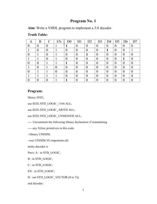
  • 1. 1 Program No. 1 Aim: Write a VHDL program to implement a 3:8 decoder. Truth Table: A B C EN D0 D1 D2 D3 D4 D5 D6 D7 0 0 0 1 1 0 0 0 0 0 0 0 1 0 0 1 0 0 0 0 1 0 0 1 0 1 0 1 0 0 1 0 0 0 0 0 1 1 0 1 0 0 0 0 0 0 1 0 0 0 1 1 1 0 0 0 0 0 0 0 1 0 1 0 0 0 0 0 0 0 0 0 0 1 1 0 0 0 0 0 0 0 0 0 1 1 1 1 0 0 0 0 0 0 0 1 0 0 0 1 1 0 0 0 0 0 0 0 Program: library IEEE; use IEEE.STD_LOGIC_1164.ALL; use IEEE.STD_LOGIC_ARITH.ALL; use IEEE.STD_LOGIC_UNSIGNED.ALL; ---- Uncomment the following library declaration if instantiating ---- any Xilinx primitives in this code. --library UNISIM; --use UNISIM.VComponents.all; entity decoder is Port ( A : in STD_LOGIC; B : in STD_LOGIC; C : in STD_LOGIC; EN : in STD_LOGIC; D : out STD_LOGIC_VECTOR (0 to 7)); end decoder;
  • 2. 2 architecture Behavioral of decoder is begin process(A,B,C,EN) variable ABAR,BBAR,CBAR:STD_LOGIC; begin ABAR :=NOT A; BBAR :=NOT B; CBAR :=NOT C; if EN='1' then D(0)<= ABAR AND BBAR AND CBAR; D(1)<= ABAR AND BBAR AND C; D(2)<= ABAR AND B AND CBAR; D(3)<= ABAR AND B AND C; D(4)<= A AND BBAR AND CBAR; D(5)<= A AND BBAR AND C; D(6)<= A AND B AND CBAR; D(7)<= A AND B AND C; else D <= "00000000"; end if; end process; end Behavioral;
  • 3. 3 RTL Logic: Output Waveform: Result: VHDL Program of a 3 :8 decoder has been implemented
  • 4. 4 Program No. 2 Aim: Write a VHDL program to implement an 8:1 multiplexer. Truth Table: S0 S1 S2 A0 A1 A2 A3 A4 A5 A6 A7 Z 0 0 0 0 0 0 0 0 0 0 0 0 1 0 0 0 0 0 0 0 0 0 1 0 0 1 0 1 0 0 0 1 0 1 0 0 1 1 0 1 1 1 1 1 1 1 0 1 0 0 1 1 0 1 1 0 1 1 1 0 1 0 1 0 0 1 0 1 1 1 0 1 0 1 1 1 1 1 0 1 0 1 0 0 1 1 1 1 0 1 1 1 0 0 1 1 0 0 0 1 0 1 1 0 1 0 1 1 Program:- library IEEE; use IEEE.STD_LOGIC_1164.ALL; use IEEE.STD_LOGIC_ARITH.ALL; use IEEE.STD_LOGIC_UNSIGNED.ALL; ---- Uncomment the following library declaration if instantiating
  • 5. 5 ---- any Xilinx primitives in this code. --library UNISIM; --use UNISIM.VComponents.all; entity Ramkrishna_MUX is Port ( A : in STD_LOGIC_VECTOR (0 to 7); S : in STD_LOGIC_VECTOR (0 to 2); Z : out STD_LOGIC); end Ramkrishna_MUX; architecture Behavioral of Ramkrishna_MUX is begin process (S,A) is begin case S is when "000" => Z<=A(0); when "001" => Z<=A(1); when "010" => Z<=A(2); when "011" => Z<=A(3); when "100" => Z<=A(4); when "101" => Z<=A(5); when "110" => Z<=A(6); when "111" => Z<=A(7); when others => Z<='X'; end case; end process; end Behavioral;
  • 6. 6 RTL Logic: Output Waveform: Result: VHDL Program of 8:1 multiplexer has been implemented using behavioral modeling.
  • 7. 7 Program No: 3 Aim:- To write a VHDL program to implement a 1:8 demultiplexer. Truth Table:- A S2 S1 S0 Z0 Z4 Z2 Z6 Z1 Z5 Z3 Z7 0 0 0 0 0 0 0 0 0 0 0 0 1 1 0 0 - 1 1 1 1 1 1 1 0 0 1 0 - - 0 0 0 0 0 0 1 1 1 0 - - - 1 1 1 1 1 0 0 0 1 - - - - 0 0 0 0 1 1 0 1 - - - - - 1 1 1 0 0 1 1 - - - - - - 0 0 1 1 1 1 - - - - - - - 1 Program:- library IEEE; use IEEE.STD_LOGIC_1164.ALL; use IEEE.STD_LOGIC_ARITH.ALL; use IEEE.STD_LOGIC_UNSIGNED.ALL; ---- Uncomment the following library declaration if instantiating ---- any Xilinx primitives in this code. --library UNISIM; --use UNISIM.VComponents.all; entity DEMUX is Port ( A : in STD_LOGIC; S : in STD_LOGIC_VECTOR(0 TO 2); Z : out STD_LOGIC_VECTOR(0 TO 7)); end DEMUX; architecture Behavioral of DEMUX is BEGIN
  • 8. 8 PROCESS(A,S) BEGIN CASE S IS WHEN "000"=>Z(0)<=A; WHEN "001"=>Z(1)<=A; WHEN "010"=>Z(2)<=A; WHEN "011"=>Z(3)<=A; WHEN "100"=>Z(4)<=A; WHEN "101"=>Z(5)<=A; WHEN "110"=>Z(6)<=A; WHEN "111"=>Z(7)<=A; WHEN OTHERS=>Z<="XXXXXXXX"; END CASE; END PROCESS; end Behavioral;
  • 9. 9 RTL Diagram:- Output Waveform:- Result: A VHDL Program of 1 :8 demultiplexer has been implemented by behavioral modeling.
  • 10. 10 Program No. 4 Aim: Write a VHDL program to implement 4-bit addition/subtraction. Truth Table: Program: library IEEE; use IEEE.STD_LOGIC_1164.ALL; use IEEE.STD_LOGIC_ARITH.ALL; use IEEE.STD_LOGIC_UNSIGNED.ALL; ---- Uncomment the following library declaration if instantiating ---- any Xilinx primitives in this code. --library UNISIM; --use UNISIM.VComponents.all; entity BIT_ADDER_SUB is Port ( A : in STD_LOGIC_VECTOR (3 downto 0); B : in STD_LOGIC_VECTOR (3 downto 0); M : in STD_LOGIC; C_IN : inout STD_LOGIC; C_OUT : out STD_LOGIC; S : out STD_LOGIC_VECTOR (3 downto 0)); end BIT_ADDER_SUB; A0 A1 A2 A3 B0 B1 B2 B3 M CIN COUT S0 S1 S2 S3 0 1 0 0 0 0 0 0 1 1 1 0 1 0 0 0 0 1 0 1 0 0 0 0 0 0 1 1 0 0 0 1 1 0 1 1 0 0 1 1 1 1 0 0 0 0 0 0 1 1 0 1 0 0 0 0 1 1 1 0 0 1 0 1 1 1 1 0 1 1 1 1 0 0 0 0 0 1 1 1 0 0 1 0 0 0 1 1 1 1
  • 11. 11 architecture Behavioral of BIT_ADDER_SUB is begin PROCESS(A,B,M,C_IN) VARIABLE C:STD_LOGIC_vector(0 to 3); VARIABLE B0BAR,B1BAR,B2BAR,B3BAR:STD_LOGIC; BEGIN C_IN<=M; B0BAR:=NOT B(0); B1BAR:=NOT B(1); B2BAR:=NOT B(2); B3BAR:=NOT B(3); IF M='0' THEN C(0):=((A(0)AND B(0))OR (A(0)AND C_IN)OR (B(0) AND C_IN)); C(1):=((A(1) AND B(1)) OR (A(1) AND C(0)) OR (B(1) AND C(0))); C(2):=((A(2) AND B(2)) OR (A(2) AND C(1)) OR (B(2) AND C(1))); S(0)<=(A(0)XOR B(0) XOR C_IN); S(1)<=(A(1) XOR B(1) XOR C(0)); S(2)<=(A(2) XOR B(2) XOR C(1)); S(3)<=(A(3) XOR B(3) XOR C(2)); C_OUT<=((A(3) AND B(3))OR (A(3) AND C(2)) OR (B(3) AND C(2))); ELSE C(0):=((A(0) AND B0BAR)OR (B0BAR AND C_IN)OR (A(0) AND C_IN)); C(1):=((A(1) AND B1BAR)OR (B1BAR AND C(0))OR (A(1) AND C(0))); C(2):=((A(2) AND B2BAR) OR (B2BAR AND C(1)) OR (A(2) AND C(1))); S(0)<=(A(0) XOR B0BAR XOR C_IN); S(1)<=(A(1) XOR B1BAR XOR C(0)); S(2)<=(A(2) XOR B2BAR XOR C(1)); S(3)<=(A(3) XOR B3BAR XOR C(2));
  • 12. 12 C_OUT<=((A(3)AND B3BAR) OR (B3BAR AND C(2)) OR (A(3) AND C(2))); END IF; END PROCESS; end Behavioral;
  • 13. 13 RTL Logic: Output Waveform: Result: VHDL Program to implement 4 bit addition/subtraction have been studied.
  • 14. 14 Program No: 5 Aim: Write a VHDL program to implement a 4-bit comparator. Truth Table: A0 A1 A2 A3 B0 B1 B2 B3 AGB AEB ALB 0 0 0 0 0 0 0 0 0 1 0 1 1 1 0 1 0 0 1 1 0 0 0 1 0 0 0 0 0 1 1 0 0 1 0 0 1 1 0 0 1 0 1 0 0 1 0 1 1 0 1 0 0 0 1 0 0 1 1 1 1 1 0 0 0 1 1 0 1 0 1 0 1 0 0 1 0 1 1 1 0 1 0 0 1 1 0 0 0 1 1 0 1 0 0 0 0 0 1 Program: library IEEE; use IEEE.STD_LOGIC_1164.ALL; use IEEE.STD_LOGIC_ARITH.ALL; use IEEE.STD_LOGIC_UNSIGNED.ALL; ---- Uncomment the following library declaration if instantiating ---- any Xilinx primitives in this code. --library UNISIM; --use UNISIM.VComponents.all; entity COMPARATOR is Port ( A : in STD_LOGIC_VECTOR (0 to 3); B : in STD_LOGIC_VECTOR (0 to 3); AGB : out STD_LOGIC; AEB : out STD_LOGIC; ALB : out STD_LOGIC); end COMPARATOR;
  • 15. 15 architecture Behavioral of COMPARATOR is begin PROCESS(A,B) BEGIN IF A>B THEN AGB <='1'; AEB <='0'; ALB <='0'; ELSIF A=B THEN AGB<='0'; AEB<='1'; ALB<='0'; ELSIF A<B THEN AGB<='0'; AEB<='0'; ALB<='1'; END IF; END PROCESS; END BEHAVIORAL;
  • 16. 16 RTL Logic: Output Waveform: Result: A VHDL Program of 4 bit comparator has been implemented.
  • 17. 17 Program No: 6 Aim: Write a VHDL program to implement MOD-10 counter. Truth Table: SLOAD CLR Q0 Q1 Q2 Q3 1 1 0 0 0 0 1 0 0 0 0 1 1 0 0 0 1 0 1 0 0 0 1 1 1 0 0 1 0 0 1 0 0 1 0 1 1 0 0 1 1 0 1 0 0 1 1 1 1 0 1 0 0 0 1 0 1 0 0 1 1 0 0 0 0 0 1 0 0 0 0 1 Program: library IEEE; use IEEE.STD_LOGIC_1164.ALL; use IEEE.STD_LOGIC_ARITH.ALL; use IEEE.STD_LOGIC_UNSIGNED.ALL;
  • 18. 18 ---- Uncomment the following library declaration if instantiating ---- any Xilinx primitives in this code. --library UNISIM; --use UNISIM.VComponents.all; entity MOD_10 is Port ( CLK : in STD_LOGIC; SLOAD : in STD_LOGIC; CLR : in STD_LOGIC; Q : out STD_LOGIC_VECTOR (0 to 3)); end MOD_10; architecture Behavioral of MOD_10 is SIGNAL TEMP:STD_LOGIC_VECTOR(0 TO 3); begin PROCESS (CLK) IS BEGIN IF (CLK'EVENT AND CLK='1') THEN IF CLR='1' THEN TEMP <= "0000"; ELSIF SLOAD ='1' THEN IF TEMP="1001" THEN TEMP<= "0000"; ELSE TEMP<=TEMP+"0001"; END IF; END IF; END IF; END PROCESS; Q<=TEMP; END BEHAVIORAL;
  • 19. 19 RTL Logic: Output Waveform: Result: A VHDL Program to generate Mod- 10 up counter has been implemented.
  • 20. 20 Program No. 7 Aim: To write a VHDL program to generate the 1010 sequence detector. Truth Table: X Z 0 0 0 0 0 0 0 0 1 0 0 0 1 0 0 1 0 0 0 0 0 0 Program: library IEEE; use IEEE.STD_LOGIC_1164.ALL; use IEEE.STD_LOGIC_ARITH.ALL; use IEEE.STD_LOGIC_UNSIGNED.ALL; ---- Uncomment the following library declaration if instantiating ---- any Xilinx primitives in this code. --library UNISIM; --use UNISIM.VComponents.all; entity SEQ_DETECTOR is Port ( X : in STD_LOGIC;
  • 21. 21 CLK : in STD_LOGIC; Z : out STD_LOGIC); end SEQ_DETECTOR; architecture Behavioral of SEQ_DETECTOR is TYPE STATE_TYPE IS (S0,S1,S2,S3); SIGNAL CURRENT_STATE,NEXT_STATE:STATE_TYPE; BEGIN PROCESS(CURRENT_STATE,X) begin CASE CURRENT_STATE IS WHEN S0=> IF X='0' THEN Z<='0'; NEXT_STATE<= S0; ELSIF X='1' THEN Z<='0'; NEXT_STATE <=S1; ELSE Z<='0'; NEXT_STATE <=S0; END IF; WHEN S1=> IF X='0' THEN Z<='0'; NEXT_STATE <= S2; ELSIF X='1' THEN Z<='0'; NEXT_STATE <=S1; ELSE Z<= '0';
  • 22. 22 NEXT_STATE <=S0; END IF; WHEN S2=> IF X='0' THEN Z<='0'; NEXT_STATE<= S0; ELSIF X='1' THEN Z<='0'; NEXT_STATE<=S3; ELSE Z<='0'; NEXT_STATE <=S0; END IF; WHEN S3=> IF X='0' THEN Z<='1'; NEXT_STATE<= S1; ELSIF X='1' THEN Z<='1'; NEXT_STATE<=S0; ELSE Z<='0'; NEXT_STATE<=S0; END IF; END CASE; WAIT UNTIL CLK='1'AND CLK'EVENT; CURRENT_STATE<=NEXT_STATE; END PROCESS; end Behavioral;
  • 23. 23 RTL Logic: Output Waveform: Result: A VHDL Program to generate the 1010 sequence detector has been studied.
  • 24. 24 Program No. 8 Aim: To write a VHDL program to perform serial to parallel transfer of 4- bit binary number. Truth Table: CLR PR DIN Y(0) Y(1) Y(2) Y(3) 1 1 1 - - - - 1 1 0 1 - - - 1 1 1 0 1 - - 1 1 0 1 0 1 - 1 1 1 0 1 0 1 1 1 0 1 0 1 0 1 1 1 0 1 0 1 1 1 0 1 0 1 0 1 1 1 0 1 0 1 Program: library IEEE; use IEEE.STD_LOGIC_1164.ALL; use IEEE.STD_LOGIC_ARITH.ALL; use IEEE.STD_LOGIC_UNSIGNED.ALL; ---- Uncomment the following library declaration if instantiating ---- any Xilinx primitives in this code. --library UNISIM; --use UNISIM.VComponents.all; entity SIPO is Port ( D : in STD_LOGIC; CLR : in STD_LOGIC; CLK : in STD_LOGIC;
  • 25. 25 PR : in STD_LOGIC; Y : out STD_LOGIC_VECTOR(0 TO 3)); end SIPO; architecture Behavioral of SIPO is SIGNAL A:STD_LOGIC_VECTOR(0 TO 3); begin PROCESS(CLR,CLK,PR,D) BEGIN IF(CLR='1' AND PR='1' AND CLK='1' AND CLK'EVENT)THEN A(0)<=D; A(1)<=A(0); A(2)<=A(1); A(3)<=A(2); Y<=A; ELSIF(CLR='1' AND PR='0')THEN Y<="1111"; ELSIF (CLR='0' AND PR='1')THEN Y<="0000"; END IF; END PROCESS; end Behavioral;
  • 26. 26 RTL LOGIC: Output Waveform: Result: A VHDL program of serial to parallel transfer of 4 bit binary number has been verified.
  • 27. 27 Program No. 9 Aim: To write a program to perform parallel to serial transfer of 4-bit binary number. Truth Table: Din Clk Load Dout 0 1 1 - 0 0 0 0 1 1 1 0 1 0 0 1 2 1 1 0 2 0 0 2 3 1 1 0 3 0 0 3 Program: library IEEE; use IEEE.STD_LOGIC_1164.ALL; use IEEE.STD_LOGIC_ARITH.ALL; use IEEE.STD_LOGIC_UNSIGNED.ALL; ---- Uncomment the following library declaration if instantiating ---- any Xilinx primitives in this code. --library UNISIM; --use UNISIM.VComponents.all; entity PISO is Port ( din : in STD_LOGIC_VECTOR (3 downto 0); load_shtbar : in STD_LOGIC; clk : in STD_LOGIC; dout : out STD_LOGIC);
  • 28. 28 end PISO; architecture Behavioral of PISO is signal sr_bit:std_logic_vector(3 downto 0):="0000"; begin process(clk) begin if (clk='1' and clk'event)then if(load_shtbar ='1')then sr_bit <=din; else sr_bit<='0'& sr_bit(3 downto 1); end if; dout<=sr_bit(0); end if; end process; end Behavioral;
  • 29. 29 RTL Logic: Output Waveform Result: A VHDL program of parallel to serial transfer of 4 bit binary number has been verified.
  • 30. 30 Program No: 10 Aim: Write a VHDL program to implement BCD to Seven segments Decoder. Truth Table: BCD 0 BCD 1 BCD 2 BCD 3 LED 0 LED 1 LED 2 LED 3 LED 4 LED 5 LED 6 0 0 0 0 0 1 1 1 1 1 1 1 0 0 0 1 1 1 1 1 1 1 0 1 0 0 1 1 0 0 1 1 0 1 1 0 0 0 0 0 0 0 0 0 0 0 1 0 1 0 1 1 0 1 1 1 0 1 0 0 0 0 0 0 0 0 0 1 1 0 1 1 1 1 1 0 1 1 1 1 0 0 0 0 0 0 0 0 0 0 0 1 0 0 0 0 1 1 0 Program: library IEEE; use IEEE.STD_LOGIC_1164.ALL; use IEEE.STD_LOGIC_ARITH.ALL; use IEEE.STD_LOGIC_UNSIGNED.ALL; ---- Uncomment the following library declaration if instantiating ---- any Xilinx primitives in this code. --library UNISIM; --use UNISIM.VComponents.all; entity BCD_7SEGMENT is Port ( BCD : in STD_LOGIC_VECTOR (3 downto 0); LED : out STD_LOGIC_VECTOR (6 downto 0));
  • 31. 31 end BCD_7SEGMENT; architecture Behavioral of BCD_7SEGMENT is BEGIN PROCESS(BCD)IS begin CASE BCD IS WHEN "0000"=>LED<="1111110"; WHEN "0001"=>LED<="0110000"; WHEN "0010"=>LED<="1101101"; WHEN "0011"=>LED<="1111001"; WHEN "0100"=>LED<="0110011"; WHEN "0101"=>LED<="1011011"; WHEN "0110"=>LED<="1011111"; WHEN "0111"=>LED<="1110000"; WHEN "1000"=>LED<="1111111"; WHEN "1001"=>LED<="1111011"; WHEN OTHERS=>LED<="0000000"; END CASE; END PROCESS; end Behavioral;
  • 32. 32 RTL Logic: Output Waveform: Result: A VHDL Program of BCD to SEVEN SEGMENT display has been implemented.
  • 33. 33 Program No. 11 Aim: Write a program to convert 8 bit vector into an integer. Truth Table: Program: library IEEE; use IEEE.STD_LOGIC_1164.ALL; use IEEE.STD_LOGIC_ARITH.ALL; use IEEE.STD_LOGIC_UNSIGNED.ALL; ---- Uncomment the following library declaration if instantiating ---- any Xilinx primitives in this code. --library UNISIM; --use UNISIM.VComponents.all; entity CONVERTOR is Port ( A : in BIT_VECTOR (0 to 7); OP : out INTEGER RANGE 0 to 255); end CONVERTOR; A3 A2 A1 A0 S0 S1 S2 S3 S4 S5 S6 0 0 0 0 0 1 1 1 1 1 1 0 0 0 1 0 1 1 0 0 0 0 0 0 1 0 1 1 0 1 1 0 1 0 0 1 1 1 1 1 1 0 0 1 0 1 0 0 0 1 1 0 0 1 1 0 1 0 1 1 0 1 1 0 1 1 0 1 1 0 0 0 1 1 1 1 1 0 1 1 1 1 1 1 0 0 0 0 1 0 0 0 1 1 1 1 1 1 1 1 0 0 1 1 1 1 0 0 1 1 * * * * 0 1 1 1 1 1 1
  • 34. 34 architecture Behavioral of CONVERTOR is IMPURE FUNCTION CONV(X:BIT_VECTOR(0 TO 7)) RETURN INTEGER IS VARIABLE T:INTEGER; begin T:=0; FOR I IN 0 TO 7 LOOP IF A(I)='1' THEN T:=T+2**I; END IF; END LOOP; RETURN T; END FUNCTION CONV; BEGIN OP<=CONV(A); end Behavioral;
  • 35. 35 RTL Logic: WAVEFORM: RESULT: A program to convert 8 bit vector into an integer have been studied.