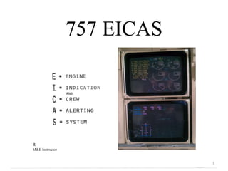
SlideShare uma empresa Scribd logo
1 de 22
757 EICAS


R
M&E Instructor


                             1
757 EICAS

• DESCRIPTION AND OPERATION

• COMPONENTS

• MAINTENANCE

• Q&A


                              2
The engine Indication and Crew Alerting System
(EICAS) includes two color Display Units
(DU), two computers, and two control panels. In
addition to these components we have
cancel/recall switches , and captain’s and first
officer’s master caution lights, jointly perform
the various EICAS functions.

The EICAS computer process and formats data
to display all engine and airplane system
information required by the crew. Only one
computer is used at any particular time for
displaying the data on both display units. The left
computer is always the primary one and right is
secondary. Manual computer selection can be
done on the display control panel.


                                                      3
4
EICAS DISPLAY CATEGORIES
EICAS is designed to categorize alerts and displays
according to function and usage. This results in three
modes of display:

•Operational Mode
•Status Mode
•Maintenance mode

Operational Mode display those engine parameters
required on the ground and in flight operation and
provide monitoring of the airplane and engine
subsystems. The upper DU is dedicated full time to
primary engine parameters and alert messages for
monitoring by the crew. The lower DU shows
secondary engine parameters.

Status Mode provide subsystem parameters as well
as status messages on the lower DU. This are used
by the crew to determine readiness of the airplane
for dispatch and closely associated with the MEL.

Maintenance Mode provide airplane subsystems
parameters and maintenance messages on the lower
DU. This data is available on the ground only for
post-flight maintenance and troubleshooting action.


                                                                    5
EICAS OPERATIONAL MODE

Primary engine parameters displayed on the upper DU
are EPR, N1 and EGT.
This are required to set and monitor thrust. All primary
parameters are displayed by a digital readout and an
analog pointer.
Alert Messages are display in the upper DU left corner.

Secondary Engine Parameters – N2, N3, fuel flow, oil
pressure, oil temperature, oil quantity and vibration –
are displayed on the lower DU at power up or when
manually selected on the display selector panel.
Secondary parameters are displayed by a digital
readout and an analog pointer.

EICAS automatically display engine exceedance
condition and the respective color for fast crew
attention and action.


                                                                    6
EICAS ALERT MESSAGES & CANCEL/RECALL


Alert messages displayed on the upper DU are divided by   Cancel and Recall switches control the display of this
priority:                                                 messages, Cancel remove any caution and advisory messages
• Warnings - Red required immediate action.               from the upper display and will show the next page of Messages
• Cautions - Yellow.                                      if any. RECALL switch will return to view those Messages that
                                                          are still applicable.
• Advisories -Yellow and are indented.
                                                          Warning Messages can not be canceled due to the level of
• White - data or communication.                          importance related to them.


                                                                                                                           7
EICAS DISPLAY CONTROL PANEL

The display select panel provides all control function to the
EICAS computer units system operation both in flight and on the
ground. The display select panel functions include:
• Display format selection:                                     • Display brightness control:
       ENG and STATUS.                                                upper and lower.
•Recording subsystem parameters:                                • Thrust reference setting control:
        EVENT RECORD
                                                                        AUTO/MANUAL
• Computer source selection:                                    • Clearing/display engine exceedance data:
        L, both and R.                                                 MAX IND RESET


                                                                                                             8
EICAS STATUS MODE
The Status Mode display is selected by manually pressing
the STATUS switch on the display select panel. Data
needed by the crew to determined readiness for dispatch is
displayed on the upper left corner.
On the upper right corner the following are displayed

• HYD QTY and PSI.
•APU RPM/EGT all displayed in digital format.
• Crew O2 PSI.


In addition on the lower left corner analog pointers are
used to indicate the position of the Rudder, Elevators and
Aileron control surfaces.

The status mode can be useful in flight for anticipating
possible ground maintenance action that will be required if
equipped or activated prior dispatch. For this function, a
STATUS cue is provided in the upper left corner lower DU
whenever a change in status Msg occurs while the status
page is not being displayed.
For specific messages refer to the FIM, if a DU fails in
flight, the status cue and status displays are inhibited until
airplane is on the ground.


                                                                      9
EICAS MAINTENACE MODE/PANEL


There are five maintenance formats with on the EICAS
Maintenance Mode. They are designed to provide maintenance            • Environmental Control Systems/Messages - ECS/MSG
information to aid the ground crew in troubleshooting and             • Electrical/Hydraulic - ELEC/HYD
verification testing of the major subsystems. They are also used to
record systems parameters on the ground or at the time of an in-      •Performance/Auxiliary Power Unit – PERF/APU
flight fault for later readout on the ground                          • Engine Exceedance – ENG EXCD
The five different formats are displayed in the lower DU and          •The Configuration Porting – CONF/MCDP
access from the EICAS Maintenance Panel this provides all the
controls functions for maintenance and troubleshooting                The EICAS maintenance panel contains BITE switch to initiate
information , the I/O signals interfaces with the air-ground relay    the SELF bite function of the two computers.
and the display panel:                                                Also on the Maintenance control panel contains the
                                                                      AUTO/MANUAL EVENT read switches and REC/ERASE
                                                                      switches.


                                                                                                                                10
11
EICAS AUTO AND MANUAL EVENT DISPLAY & RECORDING
EICAS feature automatic event recording of
the subsystems parameters . Whenever certain
auto or manual events messages are initiated
by one of the following subjects:
• APU subsystem.
• Electrical subsystem.
• Engine performance
• Environmental control system.
• Hydraulic subsystem.

This events are recorded on a nonvolatile
memory for later readout and evaluation. The
AUTO (or MANUAL) switch on the
maintenance panel is use to access and erase
this pages.

The Manual Event recording will store
discrete from engine parameters or either the
ECS/MSG, ELEC/HYD, or PERF/APU
maintenance formats. The last data stored
overwrites previously stored data, only the last
data is available for review.


                                                                  12
RH IDG High out temp
Date and time
                       13
ENGINE EXCEEDANCE DATA
To erase the auto recorded values of engines exceedance, call up the Since the Stored exceedance are automatically displayed when the
ENG EXCD page by pressing the ENG EXCD switch on the                 form is called up, the AUTO or MAN events read switches do not
maintenance panel and then press the ERASE switch.                   have to be used. You must also clear exceedance from the Display
                                                                     Select Panel.


                                                                                                                                 14
EICAS COMPUTERS
The EICAS computer are located in the main electronic             and the circuit breakers are located on the overhead P11 panel.
equipment compartment on the E4-2 rack. The computer unit         Normally (AUTO) the left computer is on command of displays
perform all interface, data processing, control and display       and the right computer is on backup mode in case the left fails.
generation function required and is software controlled.          Manual selection of the active computer is provided by selecting
                                                                  L or R rather than the AUTO position .
The front case has no system lights, BITE or controls. There is a
connector for software load with the appropriate tool or          Care should be taken when replacing this computer due to
equipment. There is also a data load point in the flight deck     electrostatic sensitivity devise.
behind the F/O on P61.

115 VAC is supplied from the respective right and left ac buses


                  P61 data port


                                                                                                                                15
16
DISPLAY UNITS (DU)

The EICAS display units (DU) provide a multicolor
(red, yellow, cyan (light blue), magenta (pink), white, and green)
CRT presentation of EICAS data.

Video display and deflection signals from the EICAS switching
modules are provided to drive the CRTs.

Manual and automatic intensity signals are provided from the
display select panel and from remote light sensors in the upper
right corner of the front panel.

EICAS DU problems that are detected within each unit
like, beam stuck on or off, failure discrete, or over temperature
will cause the unit to shut down automatically.

The DU are interchangeable, to remove, unscrew the handle, lift
and pull out, refer to the AMM for proper procedure.


                                                                     17
18
EICAS BITE OPERATION


EICAS BITE test can only be accomplished when the airplane is on the
ground and the parking brake set.

The EICAS self test mode is initiated by pressing the TEST switch on
the EICAS maintenance panel.
After depressing the TEST switch, the DUs will display:

       •Identical formats with the message “TEST IN PROCESS”.
       •Master CAUTION lights and the beeper tone are acute.
       •Level B aural command output signal are generated.
       •The master WARNING lights, the CONFIG light and siren are
       activated.
       •The takeoff ground signal is generated.
       •The SEI comes on if selected on auto.

The computer will test the interface and circuits of the complete
EICAS system and will display all characters and colors. The FIM is
used for any faults noted.

When the test is completed a massage: TEST OK, SELF TEST
COMPLETED or TEST FAIL is displayed.


                                                                          19
20
STANDBY ENGINE INDICATOR


The Standby Engine Indicator(SEI) provides primary
Engine information to the flight crew in the event of an
EICAS failure, which will result n the loss of the normal
primary engine Parameters displays.

 When operating , the SEI presents digital LCD Displays
of the primary engine parameters. This displays include
EPR, N1, EGT and N3 and the max values are shown on
red decals next to the digits. The SEI is controlled by a
switch on the front with two positions, ON and AUTO.

To perform a display test, a spring loaded switch located
opposite to the On/off switch is used, the digital numbers
will read ones and eight.

This is a LRU and does not required special software. The
engine placards must be removed from the old and
installed on the new one.


                                                               21
Q&A


      22

Mais conteúdo relacionado

Mais procurados

5.1 Electronic Instrument Systems
5.1 Electronic Instrument Systems5.1 Electronic Instrument Systems
5.1 Electronic Instrument Systems
lpapadop
 
B747 Electrical Power
B747 Electrical PowerB747 Electrical Power
B747 Electrical Power
theoryce
 

Mais procurados (20)

B737 NG Autoflight Part 1
B737 NG Autoflight Part 1B737 NG Autoflight Part 1
B737 NG Autoflight Part 1
 
How to Fly a Boeing 737 - Quick & Easy Basics
How to Fly a Boeing 737 - Quick & Easy BasicsHow to Fly a Boeing 737 - Quick & Easy Basics
How to Fly a Boeing 737 - Quick & Easy Basics
 
B737NG Aircraft general
B737NG Aircraft generalB737NG Aircraft general
B737NG Aircraft general
 
B737 NG Engines
B737 NG EnginesB737 NG Engines
B737 NG Engines
 
Alaska Airlines Airbus Study Presentation 2
Alaska Airlines Airbus Study Presentation 2Alaska Airlines Airbus Study Presentation 2
Alaska Airlines Airbus Study Presentation 2
 
B737 NG Communications
B737 NG CommunicationsB737 NG Communications
B737 NG Communications
 
B737 NG Air Systems
B737 NG Air SystemsB737 NG Air Systems
B737 NG Air Systems
 
B737NG FMC
B737NG FMCB737NG FMC
B737NG FMC
 
EASA PART-66 MODULE 5.15 : TYPICAL AIRCRAFT INSTRUMENT SYSTEMS
EASA PART-66 MODULE 5.15 : TYPICAL AIRCRAFT INSTRUMENT SYSTEMSEASA PART-66 MODULE 5.15 : TYPICAL AIRCRAFT INSTRUMENT SYSTEMS
EASA PART-66 MODULE 5.15 : TYPICAL AIRCRAFT INSTRUMENT SYSTEMS
 
B737 NG APU
B737 NG APUB737 NG APU
B737 NG APU
 
Fire protection
Fire protectionFire protection
Fire protection
 
5.1 Electronic Instrument Systems
5.1 Electronic Instrument Systems5.1 Electronic Instrument Systems
5.1 Electronic Instrument Systems
 
B737 NG Fuel System.
B737 NG Fuel System.B737 NG Fuel System.
B737 NG Fuel System.
 
B737mrg exterior inspection
B737mrg exterior inspectionB737mrg exterior inspection
B737mrg exterior inspection
 
EASA part 66 module exam Module - 5 EFIS(Electronic Flight instrument system)
EASA part 66 module exam Module - 5 EFIS(Electronic Flight instrument system)EASA part 66 module exam Module - 5 EFIS(Electronic Flight instrument system)
EASA part 66 module exam Module - 5 EFIS(Electronic Flight instrument system)
 
737 ng cl differences jakub muransky
737 ng cl differences jakub muransky737 ng cl differences jakub muransky
737 ng cl differences jakub muransky
 
B737NG Anti ice and rain
B737NG Anti ice and rainB737NG Anti ice and rain
B737NG Anti ice and rain
 
B737 NG Flight controls
B737 NG Flight controlsB737 NG Flight controls
B737 NG Flight controls
 
B747 Electrical Power
B747 Electrical PowerB747 Electrical Power
B747 Electrical Power
 
Avionics
AvionicsAvionics
Avionics
 

Destaque

757 767 study guide
757 767 study guide757 767 study guide
757 767 study guide
aviation319
 
5.15 Typical electronic digital aircraft systems
5.15 Typical electronic digital aircraft systems5.15 Typical electronic digital aircraft systems
5.15 Typical electronic digital aircraft systems
lpapadop
 
Fc744 Landingear
Fc744 LandingearFc744 Landingear
Fc744 Landingear
theoryce
 
Aircraft instrumentsystems
Aircraft instrumentsystemsAircraft instrumentsystems
Aircraft instrumentsystems
Mahnil
 
Piston engine powerplant
Piston engine powerplantPiston engine powerplant
Piston engine powerplant
Johan Andhira
 
Guia para el manejo del paciente intoxicado
Guia para el manejo del paciente intoxicadoGuia para el manejo del paciente intoxicado
Guia para el manejo del paciente intoxicado
nAyblancO
 
Communication in business life
Communication in business lifeCommunication in business life
Communication in business life
Filip Buček
 

Destaque (18)

757 767 study guide
757 767 study guide757 767 study guide
757 767 study guide
 
indicating recording systems
indicating recording systemsindicating recording systems
indicating recording systems
 
5.15 Typical electronic digital aircraft systems
5.15 Typical electronic digital aircraft systems5.15 Typical electronic digital aircraft systems
5.15 Typical electronic digital aircraft systems
 
Fc744 Landingear
Fc744 LandingearFc744 Landingear
Fc744 Landingear
 
Armature & field coil inspection
Armature & field coil inspectionArmature & field coil inspection
Armature & field coil inspection
 
Aines
AinesAines
Aines
 
Aircraft instrumentsystems
Aircraft instrumentsystemsAircraft instrumentsystems
Aircraft instrumentsystems
 
Piston engine powerplant
Piston engine powerplantPiston engine powerplant
Piston engine powerplant
 
EASA PART-66 MODULE 8.1 : PHYSICS OF ATMOSPHERE
EASA PART-66 MODULE 8.1 : PHYSICS OF ATMOSPHEREEASA PART-66 MODULE 8.1 : PHYSICS OF ATMOSPHERE
EASA PART-66 MODULE 8.1 : PHYSICS OF ATMOSPHERE
 
Guia para el manejo del paciente intoxicado
Guia para el manejo del paciente intoxicadoGuia para el manejo del paciente intoxicado
Guia para el manejo del paciente intoxicado
 
1 -efis
1  -efis1  -efis
1 -efis
 
Jacobiano
JacobianoJacobiano
Jacobiano
 
Communication in business life
Communication in business lifeCommunication in business life
Communication in business life
 
The pharaoh’s curses—the constraint from god
The pharaoh’s curses—the constraint from godThe pharaoh’s curses—the constraint from god
The pharaoh’s curses—the constraint from god
 
Stokvis Tapes
Stokvis TapesStokvis Tapes
Stokvis Tapes
 
Best Practice Guideline to Managing On-site Vermiculture Technologies
Best Practice Guideline to Managing On-site Vermiculture TechnologiesBest Practice Guideline to Managing On-site Vermiculture Technologies
Best Practice Guideline to Managing On-site Vermiculture Technologies
 
ijhff
ijhffijhff
ijhff
 
C53200
C53200C53200
C53200
 

Semelhante a 757 EICAS

mat IW 3saaaaaaaaaaaaaaaaaaaaaaaaaaaaaaaaaaaaaaaaaaaaaaaaaaaaaaaaaaaaaa
mat IW 3saaaaaaaaaaaaaaaaaaaaaaaaaaaaaaaaaaaaaaaaaaaaaaaaaaaaaaaaaaaaaamat IW 3saaaaaaaaaaaaaaaaaaaaaaaaaaaaaaaaaaaaaaaaaaaaaaaaaaaaaaaaaaaaaa
mat IW 3saaaaaaaaaaaaaaaaaaaaaaaaaaaaaaaaaaaaaaaaaaaaaaaaaaaaaaaaaaaaaa
ArifQuliyev3
 
Case IH AFS Pro 700 AFS Field Performer Large Tractors Trip Computer Precisio...
Case IH AFS Pro 700 AFS Field Performer Large Tractors Trip Computer Precisio...Case IH AFS Pro 700 AFS Field Performer Large Tractors Trip Computer Precisio...
Case IH AFS Pro 700 AFS Field Performer Large Tractors Trip Computer Precisio...
f8jsekkdkdm
 
Case IH AFS Pro 700 AFS Field Performer Large Tractors Trip Computer Precisio...
Case IH AFS Pro 700 AFS Field Performer Large Tractors Trip Computer Precisio...Case IH AFS Pro 700 AFS Field Performer Large Tractors Trip Computer Precisio...
Case IH AFS Pro 700 AFS Field Performer Large Tractors Trip Computer Precisio...
fis9ekkddmmd
 
Case IH AFS Pro600 AFS Pro700 AFS Field Performer Large Tractors Trip Compute...
Case IH AFS Pro600 AFS Pro700 AFS Field Performer Large Tractors Trip Compute...Case IH AFS Pro600 AFS Pro700 AFS Field Performer Large Tractors Trip Compute...
Case IH AFS Pro600 AFS Pro700 AFS Field Performer Large Tractors Trip Compute...
f8jsekkdkdm
 
Case IH AFS Pro600 AFS Pro700 AFS Field Performer Large Tractors Trip Compute...
Case IH AFS Pro600 AFS Pro700 AFS Field Performer Large Tractors Trip Compute...Case IH AFS Pro600 AFS Pro700 AFS Field Performer Large Tractors Trip Compute...
Case IH AFS Pro600 AFS Pro700 AFS Field Performer Large Tractors Trip Compute...
fis9ekkddmmd
 
Chapter 43
Chapter 43Chapter 43
Chapter 43
mcfalltj
 
2 8085 microprocessor
2 8085 microprocessor2 8085 microprocessor
2 8085 microprocessor
aditidey19
 

Semelhante a 757 EICAS (20)

Fabianesparzappt
FabianesparzapptFabianesparzappt
Fabianesparzappt
 
mat IW 3saaaaaaaaaaaaaaaaaaaaaaaaaaaaaaaaaaaaaaaaaaaaaaaaaaaaaaaaaaaaaa
mat IW 3saaaaaaaaaaaaaaaaaaaaaaaaaaaaaaaaaaaaaaaaaaaaaaaaaaaaaaaaaaaaaamat IW 3saaaaaaaaaaaaaaaaaaaaaaaaaaaaaaaaaaaaaaaaaaaaaaaaaaaaaaaaaaaaaa
mat IW 3saaaaaaaaaaaaaaaaaaaaaaaaaaaaaaaaaaaaaaaaaaaaaaaaaaaaaaaaaaaaaa
 
Case IH AFS Pro 700 AFS Field Performer Large Tractors Trip Computer Precisio...
Case IH AFS Pro 700 AFS Field Performer Large Tractors Trip Computer Precisio...Case IH AFS Pro 700 AFS Field Performer Large Tractors Trip Computer Precisio...
Case IH AFS Pro 700 AFS Field Performer Large Tractors Trip Computer Precisio...
 
Case IH AFS Pro 700 AFS Field Performer Large Tractors Trip Computer Precisio...
Case IH AFS Pro 700 AFS Field Performer Large Tractors Trip Computer Precisio...Case IH AFS Pro 700 AFS Field Performer Large Tractors Trip Computer Precisio...
Case IH AFS Pro 700 AFS Field Performer Large Tractors Trip Computer Precisio...
 
Fadal Diagnostics Maintenance Manual
Fadal Diagnostics Maintenance ManualFadal Diagnostics Maintenance Manual
Fadal Diagnostics Maintenance Manual
 
The ultimate guide to engine data management 800 system
The ultimate guide to engine data management 800 systemThe ultimate guide to engine data management 800 system
The ultimate guide to engine data management 800 system
 
Case IH AFS Pro600 AFS Pro700 AFS Field Performer Large Tractors Trip Compute...
Case IH AFS Pro600 AFS Pro700 AFS Field Performer Large Tractors Trip Compute...Case IH AFS Pro600 AFS Pro700 AFS Field Performer Large Tractors Trip Compute...
Case IH AFS Pro600 AFS Pro700 AFS Field Performer Large Tractors Trip Compute...
 
Case IH AFS Pro600 AFS Pro700 AFS Field Performer Large Tractors Trip Compute...
Case IH AFS Pro600 AFS Pro700 AFS Field Performer Large Tractors Trip Compute...Case IH AFS Pro600 AFS Pro700 AFS Field Performer Large Tractors Trip Compute...
Case IH AFS Pro600 AFS Pro700 AFS Field Performer Large Tractors Trip Compute...
 
2020 r1 1ok
2020 r1 1ok2020 r1 1ok
2020 r1 1ok
 
Chapter 43
Chapter 43Chapter 43
Chapter 43
 
Power plex
Power plexPower plex
Power plex
 
Volvo
VolvoVolvo
Volvo
 
ATA 31.pdf
ATA 31.pdfATA 31.pdf
ATA 31.pdf
 
Schneideratv 58 usermanual
Schneideratv 58 usermanualSchneideratv 58 usermanual
Schneideratv 58 usermanual
 
Features & specification of edm 960 twin system
Features & specification of edm 960 twin systemFeatures & specification of edm 960 twin system
Features & specification of edm 960 twin system
 
EASA Part-66 Module 5.6 : Basic Computer Structure
EASA Part-66 Module  5.6 : Basic Computer StructureEASA Part-66 Module  5.6 : Basic Computer Structure
EASA Part-66 Module 5.6 : Basic Computer Structure
 
2 8085 microprocessor
2 8085 microprocessor2 8085 microprocessor
2 8085 microprocessor
 
Plc tg fi
Plc tg fiPlc tg fi
Plc tg fi
 

Último

Último (20)

Beyond_Borders_Understanding_Anime_and_Manga_Fandom_A_Comprehensive_Audience_...
Beyond_Borders_Understanding_Anime_and_Manga_Fandom_A_Comprehensive_Audience_...Beyond_Borders_Understanding_Anime_and_Manga_Fandom_A_Comprehensive_Audience_...
Beyond_Borders_Understanding_Anime_and_Manga_Fandom_A_Comprehensive_Audience_...
 
How to Manage Global Discount in Odoo 17 POS
How to Manage Global Discount in Odoo 17 POSHow to Manage Global Discount in Odoo 17 POS
How to Manage Global Discount in Odoo 17 POS
 
Interdisciplinary_Insights_Data_Collection_Methods.pptx
Interdisciplinary_Insights_Data_Collection_Methods.pptxInterdisciplinary_Insights_Data_Collection_Methods.pptx
Interdisciplinary_Insights_Data_Collection_Methods.pptx
 
REMIFENTANIL: An Ultra short acting opioid.pptx
REMIFENTANIL: An Ultra short acting opioid.pptxREMIFENTANIL: An Ultra short acting opioid.pptx
REMIFENTANIL: An Ultra short acting opioid.pptx
 
Fostering Friendships - Enhancing Social Bonds in the Classroom
Fostering Friendships - Enhancing Social Bonds  in the ClassroomFostering Friendships - Enhancing Social Bonds  in the Classroom
Fostering Friendships - Enhancing Social Bonds in the Classroom
 
UGC NET Paper 1 Mathematical Reasoning & Aptitude.pdf
UGC NET Paper 1 Mathematical Reasoning & Aptitude.pdfUGC NET Paper 1 Mathematical Reasoning & Aptitude.pdf
UGC NET Paper 1 Mathematical Reasoning & Aptitude.pdf
 
Food safety_Challenges food safety laboratories_.pdf
Food safety_Challenges food safety laboratories_.pdfFood safety_Challenges food safety laboratories_.pdf
Food safety_Challenges food safety laboratories_.pdf
 
SOC 101 Demonstration of Learning Presentation
SOC 101 Demonstration of Learning PresentationSOC 101 Demonstration of Learning Presentation
SOC 101 Demonstration of Learning Presentation
 
Key note speaker Neum_Admir Softic_ENG.pdf
Key note speaker Neum_Admir Softic_ENG.pdfKey note speaker Neum_Admir Softic_ENG.pdf
Key note speaker Neum_Admir Softic_ENG.pdf
 
FSB Advising Checklist - Orientation 2024
FSB Advising Checklist - Orientation 2024FSB Advising Checklist - Orientation 2024
FSB Advising Checklist - Orientation 2024
 
Understanding Accommodations and Modifications
Understanding  Accommodations and ModificationsUnderstanding  Accommodations and Modifications
Understanding Accommodations and Modifications
 
NO1 Top Black Magic Specialist In Lahore Black magic In Pakistan Kala Ilam Ex...
NO1 Top Black Magic Specialist In Lahore Black magic In Pakistan Kala Ilam Ex...NO1 Top Black Magic Specialist In Lahore Black magic In Pakistan Kala Ilam Ex...
NO1 Top Black Magic Specialist In Lahore Black magic In Pakistan Kala Ilam Ex...
 
On_Translating_a_Tamil_Poem_by_A_K_Ramanujan.pptx
On_Translating_a_Tamil_Poem_by_A_K_Ramanujan.pptxOn_Translating_a_Tamil_Poem_by_A_K_Ramanujan.pptx
On_Translating_a_Tamil_Poem_by_A_K_Ramanujan.pptx
 
How to Give a Domain for a Field in Odoo 17
How to Give a Domain for a Field in Odoo 17How to Give a Domain for a Field in Odoo 17
How to Give a Domain for a Field in Odoo 17
 
Plant propagation: Sexual and Asexual propapagation.pptx
Plant propagation: Sexual and Asexual propapagation.pptxPlant propagation: Sexual and Asexual propapagation.pptx
Plant propagation: Sexual and Asexual propapagation.pptx
 
ICT role in 21st century education and it's challenges.
ICT role in 21st century education and it's challenges.ICT role in 21st century education and it's challenges.
ICT role in 21st century education and it's challenges.
 
Micro-Scholarship, What it is, How can it help me.pdf
Micro-Scholarship, What it is, How can it help me.pdfMicro-Scholarship, What it is, How can it help me.pdf
Micro-Scholarship, What it is, How can it help me.pdf
 
Sensory_Experience_and_Emotional_Resonance_in_Gabriel_Okaras_The_Piano_and_Th...
Sensory_Experience_and_Emotional_Resonance_in_Gabriel_Okaras_The_Piano_and_Th...Sensory_Experience_and_Emotional_Resonance_in_Gabriel_Okaras_The_Piano_and_Th...
Sensory_Experience_and_Emotional_Resonance_in_Gabriel_Okaras_The_Piano_and_Th...
 
Kodo Millet PPT made by Ghanshyam bairwa college of Agriculture kumher bhara...
Kodo Millet  PPT made by Ghanshyam bairwa college of Agriculture kumher bhara...Kodo Millet  PPT made by Ghanshyam bairwa college of Agriculture kumher bhara...
Kodo Millet PPT made by Ghanshyam bairwa college of Agriculture kumher bhara...
 
Sociology 101 Demonstration of Learning Exhibit
Sociology 101 Demonstration of Learning ExhibitSociology 101 Demonstration of Learning Exhibit
Sociology 101 Demonstration of Learning Exhibit
 

757 EICAS

  • 2. 757 EICAS • DESCRIPTION AND OPERATION • COMPONENTS • MAINTENANCE • Q&A 2
  • 3. The engine Indication and Crew Alerting System (EICAS) includes two color Display Units (DU), two computers, and two control panels. In addition to these components we have cancel/recall switches , and captain’s and first officer’s master caution lights, jointly perform the various EICAS functions. The EICAS computer process and formats data to display all engine and airplane system information required by the crew. Only one computer is used at any particular time for displaying the data on both display units. The left computer is always the primary one and right is secondary. Manual computer selection can be done on the display control panel. 3
  • 4. 4
  • 5. EICAS DISPLAY CATEGORIES EICAS is designed to categorize alerts and displays according to function and usage. This results in three modes of display: •Operational Mode •Status Mode •Maintenance mode Operational Mode display those engine parameters required on the ground and in flight operation and provide monitoring of the airplane and engine subsystems. The upper DU is dedicated full time to primary engine parameters and alert messages for monitoring by the crew. The lower DU shows secondary engine parameters. Status Mode provide subsystem parameters as well as status messages on the lower DU. This are used by the crew to determine readiness of the airplane for dispatch and closely associated with the MEL. Maintenance Mode provide airplane subsystems parameters and maintenance messages on the lower DU. This data is available on the ground only for post-flight maintenance and troubleshooting action. 5
  • 6. EICAS OPERATIONAL MODE Primary engine parameters displayed on the upper DU are EPR, N1 and EGT. This are required to set and monitor thrust. All primary parameters are displayed by a digital readout and an analog pointer. Alert Messages are display in the upper DU left corner. Secondary Engine Parameters – N2, N3, fuel flow, oil pressure, oil temperature, oil quantity and vibration – are displayed on the lower DU at power up or when manually selected on the display selector panel. Secondary parameters are displayed by a digital readout and an analog pointer. EICAS automatically display engine exceedance condition and the respective color for fast crew attention and action. 6
  • 7. EICAS ALERT MESSAGES & CANCEL/RECALL Alert messages displayed on the upper DU are divided by Cancel and Recall switches control the display of this priority: messages, Cancel remove any caution and advisory messages • Warnings - Red required immediate action. from the upper display and will show the next page of Messages • Cautions - Yellow. if any. RECALL switch will return to view those Messages that are still applicable. • Advisories -Yellow and are indented. Warning Messages can not be canceled due to the level of • White - data or communication. importance related to them. 7
  • 8. EICAS DISPLAY CONTROL PANEL The display select panel provides all control function to the EICAS computer units system operation both in flight and on the ground. The display select panel functions include: • Display format selection: • Display brightness control: ENG and STATUS. upper and lower. •Recording subsystem parameters: • Thrust reference setting control:  EVENT RECORD  AUTO/MANUAL • Computer source selection: • Clearing/display engine exceedance data:  L, both and R.  MAX IND RESET 8
  • 9. EICAS STATUS MODE The Status Mode display is selected by manually pressing the STATUS switch on the display select panel. Data needed by the crew to determined readiness for dispatch is displayed on the upper left corner. On the upper right corner the following are displayed • HYD QTY and PSI. •APU RPM/EGT all displayed in digital format. • Crew O2 PSI. In addition on the lower left corner analog pointers are used to indicate the position of the Rudder, Elevators and Aileron control surfaces. The status mode can be useful in flight for anticipating possible ground maintenance action that will be required if equipped or activated prior dispatch. For this function, a STATUS cue is provided in the upper left corner lower DU whenever a change in status Msg occurs while the status page is not being displayed. For specific messages refer to the FIM, if a DU fails in flight, the status cue and status displays are inhibited until airplane is on the ground. 9
  • 10. EICAS MAINTENACE MODE/PANEL There are five maintenance formats with on the EICAS Maintenance Mode. They are designed to provide maintenance • Environmental Control Systems/Messages - ECS/MSG information to aid the ground crew in troubleshooting and • Electrical/Hydraulic - ELEC/HYD verification testing of the major subsystems. They are also used to record systems parameters on the ground or at the time of an in- •Performance/Auxiliary Power Unit – PERF/APU flight fault for later readout on the ground • Engine Exceedance – ENG EXCD The five different formats are displayed in the lower DU and •The Configuration Porting – CONF/MCDP access from the EICAS Maintenance Panel this provides all the controls functions for maintenance and troubleshooting The EICAS maintenance panel contains BITE switch to initiate information , the I/O signals interfaces with the air-ground relay the SELF bite function of the two computers. and the display panel: Also on the Maintenance control panel contains the AUTO/MANUAL EVENT read switches and REC/ERASE switches. 10
  • 11. 11
  • 12. EICAS AUTO AND MANUAL EVENT DISPLAY & RECORDING EICAS feature automatic event recording of the subsystems parameters . Whenever certain auto or manual events messages are initiated by one of the following subjects: • APU subsystem. • Electrical subsystem. • Engine performance • Environmental control system. • Hydraulic subsystem. This events are recorded on a nonvolatile memory for later readout and evaluation. The AUTO (or MANUAL) switch on the maintenance panel is use to access and erase this pages. The Manual Event recording will store discrete from engine parameters or either the ECS/MSG, ELEC/HYD, or PERF/APU maintenance formats. The last data stored overwrites previously stored data, only the last data is available for review. 12
  • 13. RH IDG High out temp Date and time 13
  • 14. ENGINE EXCEEDANCE DATA To erase the auto recorded values of engines exceedance, call up the Since the Stored exceedance are automatically displayed when the ENG EXCD page by pressing the ENG EXCD switch on the form is called up, the AUTO or MAN events read switches do not maintenance panel and then press the ERASE switch. have to be used. You must also clear exceedance from the Display Select Panel. 14
  • 15. EICAS COMPUTERS The EICAS computer are located in the main electronic and the circuit breakers are located on the overhead P11 panel. equipment compartment on the E4-2 rack. The computer unit Normally (AUTO) the left computer is on command of displays perform all interface, data processing, control and display and the right computer is on backup mode in case the left fails. generation function required and is software controlled. Manual selection of the active computer is provided by selecting L or R rather than the AUTO position . The front case has no system lights, BITE or controls. There is a connector for software load with the appropriate tool or Care should be taken when replacing this computer due to equipment. There is also a data load point in the flight deck electrostatic sensitivity devise. behind the F/O on P61. 115 VAC is supplied from the respective right and left ac buses P61 data port 15
  • 16. 16
  • 17. DISPLAY UNITS (DU) The EICAS display units (DU) provide a multicolor (red, yellow, cyan (light blue), magenta (pink), white, and green) CRT presentation of EICAS data. Video display and deflection signals from the EICAS switching modules are provided to drive the CRTs. Manual and automatic intensity signals are provided from the display select panel and from remote light sensors in the upper right corner of the front panel. EICAS DU problems that are detected within each unit like, beam stuck on or off, failure discrete, or over temperature will cause the unit to shut down automatically. The DU are interchangeable, to remove, unscrew the handle, lift and pull out, refer to the AMM for proper procedure. 17
  • 18. 18
  • 19. EICAS BITE OPERATION EICAS BITE test can only be accomplished when the airplane is on the ground and the parking brake set. The EICAS self test mode is initiated by pressing the TEST switch on the EICAS maintenance panel. After depressing the TEST switch, the DUs will display: •Identical formats with the message “TEST IN PROCESS”. •Master CAUTION lights and the beeper tone are acute. •Level B aural command output signal are generated. •The master WARNING lights, the CONFIG light and siren are activated. •The takeoff ground signal is generated. •The SEI comes on if selected on auto. The computer will test the interface and circuits of the complete EICAS system and will display all characters and colors. The FIM is used for any faults noted. When the test is completed a massage: TEST OK, SELF TEST COMPLETED or TEST FAIL is displayed. 19
  • 20. 20
  • 21. STANDBY ENGINE INDICATOR The Standby Engine Indicator(SEI) provides primary Engine information to the flight crew in the event of an EICAS failure, which will result n the loss of the normal primary engine Parameters displays. When operating , the SEI presents digital LCD Displays of the primary engine parameters. This displays include EPR, N1, EGT and N3 and the max values are shown on red decals next to the digits. The SEI is controlled by a switch on the front with two positions, ON and AUTO. To perform a display test, a spring loaded switch located opposite to the On/off switch is used, the digital numbers will read ones and eight. This is a LRU and does not required special software. The engine placards must be removed from the old and installed on the new one. 21
  • 22. Q&A 22