Osisko Gold Royalties Ltd - Corporate Presentation, April 10, 2024
A Fully Integrated RF Front End for DVB-SH
1. A Fully Integrated RF Front-End for DVB-SH
H. García-Vázquez1, D. Ramos-Valido1, A. Juanicorena2, C. Luján-Martínez3,
Sunil L. Khemchandani1, J. del Pino1.
1 Institute for Applied Microelectronics, Departamento de Ingeniería Electrónica y Automática, Universidad de Las Palmas de Gran Canaria ,
2 CEIT and Tecnun (University of Navarra), Electronics and Communications dept,
3 Departamento de Ingeniería Electrónica, Escuela Superior de Ingenieros, Universidad de Sevilla.
Published in
XXV Design of Circuits and Integrated Systems Conference.
Lanzarote, Spain, 2010.
Abstract
This paper describes a RF front-end for DVB-SH (2.17-2.2 GHz) implemented in UMC CMOS 90 nm process. This
receiver includes a Low Noise Amplifier (LNA), a Single-to-Differential Converter and a Mixer. The LNA is based on
cascode topology combined with a narrow band impedance matching and LC tank load. The Single-to-Differential
Converter generates a pair of differential output signals from a single input, which have balanced amplitude and
phase. This converter is followed by a Gilbert Cell based quadrature mixer. Post-layout simulations show a
conversion gain of 33.3-32.7 dB, a 2.2 dB of noise figure, an input return loss (S11) of -15 dB and an output
compression point of 0.3 dBm. This combination draws 21.78 mW from a 1.2 V supply.
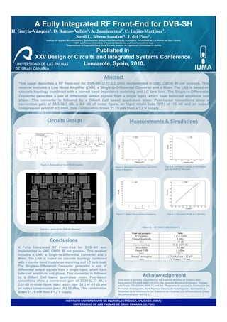
Circuits Design
Measurements & Simulations
Figure 3. Schematic of the DVB-SH receiver.
Figure 5. Simulated input return loss (S11) Figure 6. Simulation results of conversion
versus frequency. gain for DVB-SH Receiver.
0
Figure 7. Noise Figure versus frequency. Figure 8. Simulated P1dB at 2.185 GHz.
TABLE III. RF FRONT END RESULTS
Figure 4. Layout of the DVB-SH Receiver.
Conclusions
A Fully Integrated RF Front-End for DVB-SH was
implemented in UMC CMOS 90 nm process. This receiver
includes a LNA, a Single-to-Differential Converter and a
Mixer. The LNA is based on cascode topology combined
with a narrow band impedance matching and LC tank load.
The Single-to-Differential Converter generates a pair of
differential output signals from a single input, which have
balanced amplitude and phase. This converter is followed
by a Gilbert Cell based quadrature mixer. Post-layout Acknowledgement
simulations show a conversion gain of 33.26-32.73 dB, a This work is partially supported by the Spanish Ministry of Science and
Innovation (TEC2008-06881-C03-01), the Spanish Ministry of Industry, Tourism
2.24 dB of noise figure, input return loss (S11) of -15 dB and and Trade (TSI-020400-2008-71) and the “Programa de ayudas de Formación del
an output compression point of 0.29 dBm. This combination Personal investigador, de la Agencia Canaria de Investigación, Innovación y
draws 21.78 mW from a 1.2 V supply. Sociedad de la Información del Gobierno de Canarias y la cofinanciación y tasa
de cofinanciación del F.S.E.”.
INSTITUTO UNIVERSITARIO DE MICROELECTRÓNICA APLICADA (IUMA)
UNIVERSIDAD DE LAS PALMAS DE GRAN CANARIA (ULPGC)