Geophysical methods of soil/Foundation testing
•Transferir como PPT, PDF•
40 gostaram•23,485 visualizações

Geophysical methods of soil/Foundation testing

Recomendados
Mais conteúdo relacionado
Mais procurados
Mais procurados (20)
Destaque
Destaque (9)
Semelhante a Geophysical methods of soil/Foundation testing
Semelhante a Geophysical methods of soil/Foundation testing (20)
Mais de Pirpasha Ujede
Mais de Pirpasha Ujede (8)
Último
Último (20)
Geophysical methods of soil/Foundation testing
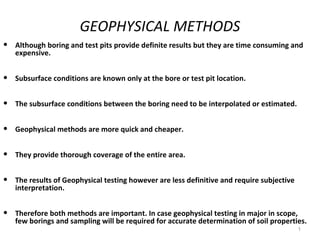
- 1. GEOPHYSICAL METHODS • Although boring and test pits provide definite results but they are time consuming and expensive. • Subsurface conditions are known only at the bore or test pit location. • The subsurface conditions between the boring need to be interpolated or estimated. • Geophysical methods are more quick and cheaper. • They provide thorough coverage of the entire area. • The results of Geophysical testing however are less definitive and require subjective interpretation. • Therefore both methods are important. In case geophysical testing in major in scope, few borings and sampling will be required for accurate determination of soil properties. 1
- 2. Geophysical methods:- Geophysical methods indicate general boundaries of drastically dissimilar layers. Most commonly used geophysical methods are:- 1.Seismic or Refraction method 2.Resistivity method
- 3. Seismic or Refraction method:- A shock wave propagates in an elastic medium with velocity, v = (M/ρ)1/2 M– modulus and ρ - mass density Wave velocity In soils 150 to 3000 m/s In rocks 1500 to 6000 m/s. Responses of a shock wave eminating from a source are picked up by geophone at known distance.
- 4. Fig. seismic refraction method
- 6. The depth of rock underlying the soil or depth of water table can be obtained. Shock waves eminating from a dynamite charge forming a source, S travel through soil & are picked up at geophones 1,2,3,…..etc. at distances d1,d2,d3…..etc. One shock wave travels directly through the top soil layer with a velocity v1 and another gets refracted with a greater velocity v2.
- 8. • The break in curve represents point of simultaneous arrival of primary & refracted waves, and its distance is known as critical distance. • The wave velocity through the rock layer is many time greater than through soil layer. • So, time of arrival by a longer route is shorter than that by the shorter route through the top soil.
- 9. d 2 − d1 Velocity, v1 = t 2 − t1 d5 − d4 Velocity, v2 = t5 − t4 The depth of rock H1 is obtained as, D V 2 −V 1 H1 = 2 V 2 + V 1 Seismic refraction method is fast. • This method is reliable in establishing profile of different strata.
- 10. The type of material in various layers can be determined by comparing the velocities obtained with the standard velocities given in table below: Type of Granite Sand Shale Hard Loose Loose Loose Rock/Soil Stone clay gravel sand sand (wet) (wet) (dry) Velocity 4000 1500 1300 600 500 500 250 (m/sec) to to to to to to to 6000 3000 3000 1500 1000 1500 600
- 11. LIMITATIONS OF THE SEISMIC METHODS The methods cannot be used if hard layer with a greater seismic velocity overlies a softer layer with a smaller seismic velocity. The methods cannot be used for the areas covered by concrete, asphalt pavements or any other artificial hard crust, having a high seismic velocity. If the area contains some underground features, such as buried conduits, irregularly dipping strata, and irregular water table, the interpretation of the results becomes very difficult. If the surface layer is frozen, the method cannot be successfully used, as it corresponds to a case of harder layer overlying a softer layer. The methods require sophisticated and costly equipment. For proper interpretations of the seismic survey results, the services of an expert are required.
- 12. Resistivity method:- Electrical resistivity method is based on the measurement & recording changes in mean resistivity of various soils. Electrical conductivity of a soil layer depends upon the concentration of ionized salts in the soil pores. Each soil has its own resistivity depending upon water content, compaction & composition.
- 13. • Low for saturated silt. • High for loose dry gravel or solid rock. • Dense rocks with few voids and little water content have high resistivity i.e. 100 to 10,000 ohm-m. • Soft saturated clays and organic deposits have low resistivity i.e. 5 to 150 ohm-m. • For a homogeneous isotropic material electrical resistivity, ρ is given as,
- 14. d d d Fig. electrical resistivity
- 16. • ρ= 2 x3.14dE • Where, I ρ = mean resistivity (ohm-m) D= distance between electrodes (cm) E= potential drop between outer electrodes (volts) I = current flowing between outer electrodes (amperes) R= resistance (ohm).
- 17. • Procedure:- It consists of using four equally spaced electrodes along a straight line. An electric current I is passed into the ground through end electrodes and induced potential is measured between the interior electrodes. The spacing is changed and the procedure is repeated. Marked change in potential indicates the presence of a stratum of different resistivity.