SlideShare uma empresa Scribd logo
1 de 11
Baixar para ler offline
6


The Rio Grande project - Argentina


6.1   Introduction

The Rio Grande pumped storage project is located on the Rio Grande river near the
town of Santa Rosa de Calamucita in the Province of Cordoba in Argentina. It has an
installed capacity of 1000 MW and provides electrical storage facilities for the power
grid and, in particular, for a nuclear power plant about 50 km away from Rio Grande.
   The project is owned by Agua y Energia Electrica, the principal Argentinean
electrical utility organisation. Preliminary feasibility studies were carried out by the
owner and these were followed by detailed design studies by Studio G. Pietrangeli of
Rome. The scheme was partly financed by Italy and some of the construction was
done by Condote de Agua, an Italian contractor. Golder Associates were involved in
the design and supervision of support installed to control the stability of most of the
major underground excavations.
   The main underground facilities are located in massive gneiss of very good
quality. The upper reservoir is impounded behind a rockfill dam and water is fed
directly from the intakes down twin penstocks which then bifurcate to feed into the
four pump-turbines. These turbines, together with valves and the control equipment,
are housed in a large underground cavern with a span of 25 m and a height of 44 m.
   Draft tubes from the turbines feed into twin tunnels which, with a down-stream
surge shaft, form the surge control system for this project. The twin tunnels join just
downstream of the surge tank and discharge into a single tailrace tunnel with a span
of 12 m and height of 18 m. This tailrace tunnel is about 6 km long and was
constructed by a full- face drill-and-blast top heading, with a span of 12 m and height
of 8m, followed by a 10 m benching operation. A view of the top heading is given in
Figure 6.1.

6.2   Tailrace tunnel support

 Because of the excellent quality of the gneiss, most of the underground excavations
did not require support and minimal provision for support was made in the contract
documents. Assessment of underground stability and installation of support, where
required, was done on a ‘design-as-you-go’ basis which proved to be very effective
and economical. Recent reports from site, many years after the start of construction
and commissioning of the plant, show that there have been no problems with rockfalls
or underground instability.
ĐƯỢC CHIA SẺ BỞI: WWW.GEOSOFTVN.COM
                       (Nếu thấy hữu ích hãy vote và chia sẻ nhé bạn)

                  SHARE BY: WWW.GEOSOFTVN.COM
                     (If you find useful, please vote and share other)

                ACTION PAR: WWW.GEOSOFTVN.COM
              (Si vous trouvez utiles, s'il vous plaît vote et d'actions, autres)

                  SHARE ПО: WWW.GEOSOFTVN.COM
(Если вы найдете полезную, пожалуйста, голосовать и обмениваться другой)

             シェア:WWW.GEOSOFTVN.COM
         (見つかった場合は、投票を共有、他のご便利です)

                  共享:WWW.GEOSOFTVN.COM
                (如果您发现有用,请投票和分享其他)
Tailrace tunnel support                                                                        83


Figure 6.1: The 12 m span 8 m high top heading for the tailrace tunnel was constructed by
full-face drill-and-blast and, because of the excellent quality of the massive gneiss, was
largely unsupported.


Figure 6.2: Mechanically anchored rockbolts of the type used on the Rio Grande project.
These bolts were tensioned to 70% of their yield load upon installation and then, at a later
stage, were re-tensioned and fully grouted.
84                                           Chapter 6: The Rio Grande project - Argentina


               Figure 6.3: A wedge failure in the roof of the top heading of
               the Rio Grande tailrace tunnel.


   Decisions on support were made on the basis of inspection of the excavated faces
by a resident team of geotechnical engineers. Where the appearance of the face
indicated that a zone of heavily jointed rock, usually associated with faulting, was
being entered, the top heading was reduced to a 6 m span by 8 m high pilot tunnel to
limit the volume of unstable rock which could be released from the roof. This pilot
tunnel was large enough to accommodate the seven-boom jumbo, as illustrated in
Figure 6.4, but small enough to limit the size of roof falls to manageable proportions.
Bolting from inside the pilot heading was used to pre-support the potentially unstable
wedges and blocks in the roof.
   In the case of the tailrace tunnel, which is itself a large excavation, the support
comprised mechanically anchored and cement grouted rockbolts as illustrated in
Figure 6.2, with mesh reinforced shotcrete where required. These bolts were
generally installed to control the type of wedge failure illustrated in Figure 6.3. In the
case of particularly large wedges, calculations of the factor of safety and support
requirements were carried out on a programmable calculator, using an early version
of the program UNWEDGE.
Support for power cavern                                                                 85


Figure 6.4: A 6 m wide heading driven ahead of the tunnel face to permit pre-reinforcement
of potentially unstable wedges in the roof. The seven-boom jumbo is seen working in the
heading.

6.3   Support for power cavern

A cross-section of the power cavern is given in Figure 6.5 and this figure includes the
five main excavation stages for the cavern. Careful mapping of significant structural
features in the roof and walls of the central access drive at the top of the cavern
provided information for estimating potentially unstable blocks and wedges which
could form in the roof of the cavern. Figure 6.6 illustrates a number of such wedges in
one section of the cavern roof. At each stage of the cavern excavation, long rockbolts
(up to 10 m length) were installed to stabilise wedges or blocks which had been
determined as being potentially unstable.
   Because gneiss has usually undergone some tectonic deformation during its
geological history, projection of structural features from visible exposures tends to be
an imprecise process. Consequently, the potentially unstable blocks and wedges had
to be reassessed after each excavation step revealed new information. The structural
plan illustrated in Figure 6.6 had to be modified many times during excavation and
that shown is the final plan prepared after the full cavern roof had been exposed.
   A general view of the cavern excavation is given in Figure 6.7. This photograph
was taken when the bulk of the cavern had been completed and only a few benches in
the bottom of the cavern remained to be excavated. The enlarged top of the cavern is
to accommodate the overhanging crane that is supported on columns from the cavern
floor. An alternative design for this cavern would have been to support the crane on
concrete beams anchored to the walls as is commonly done in good quality rock.
86   Chapter 6: The Rio Grande project - Argentina


              Figure 6.5: Cavern profile and
              excavation stages.


             Figure 6.6: A plan of the traces of
             geological features mapped in part of
             the cavern roof. The shaded areas
             represent potentially unstable wedges
             requiring reinforcement.
Discussion of support design and costs                                               87


               Figure 6.7: A view of the 25 m span Rio Grande power
               cavern during excavation of the lower benches.

6.4   Discussion of support design and costs

Apart from rockbolts installed to control isolated structurally controlled blocks and
wedges in the roof and sidewalls and some areas of closely jointed rock which were
shotcreted, the cavern was unsupported. While this was successful for this particular
project, it is not the approach which should generally be used for a critical excavation
such as an underground powerhouse.
   The damage resulting from even a small rockfall in such a cavern is out of all
proportion to the savings achieved by eliminating pattern rockbolting and full
shotcrete lining. Hence, in addition to the rockbolts installed to control structural
instability, as described earlier, I would recommend a normal pattern of 25 mm
diameter, 5 m long bolts (20% of the excavation span) on a 2.5 m grid. In addition, I
would recommend the placement of 50 mm of fibre-reinforced micro-silica shotcrete
88                                         Chapter 6: The Rio Grande project - Argentina


over the entire roof and upper sidewalls of the cavern. Based on current north
American costs, this additional support, involving approximately 600 rockbolts and
about 300 m3 of shotcrete, would have cost approximately US $200,000. In terms of
the overall project cost and the increased long-term security in the cavern, this would
normally be regarded as a good investment.
   In contrast, consider the 6 km long tailrace tunnel in which the consequences of a
small rockfall are minimal. Assume that a pattern of 4 m long bolts on a 2 m grid (say
10 bolts per section) and a 50 mm shotcrete thickness had been specified for the roof
and upper sidewalls of the tailrace tunnel. This would involve 30,000 bolts and 5,400
m3 of shotcrete at a total cost approaching US $5 million. This example illustrates the
need to give careful consideration to the function and risks associated with each
underground excavation before deciding upon the support system to be used.

6.5   Analysis using UNWEDGE program

   UNWEDGE, described in the previous chapter, is a user-friendly micro-computer
program which can be used to analyse the geometry and the stability of wedges
defined by intersecting structural discontinuities in the rock mass surrounding an
underground excavation. The analysis is based upon the assumption that the wedges,
defined by three intersecting discontinuities, are subjected to gravitational loading
only. In other words, the stress field in the rock mass surrounding the excavation is
not taken into account. While this assumption leads to some inaccuracy in the
analysis, it generally leads to a lower factor of safety than that which would occur if
the in situ stresses were taken into account.
   The application of the program UNWEDGE to the analysis of a potentially
unstable wedge in the Rio Grande cavern is illustrated in the following discussion.
6.5.1 Input Data

The dips and dip directions of a number of planes (maximum 20) can be entered
directly into the pop-up table which appears when the ‘Input data’ option is chosen or
this information can be entered in the form of a DIPS file. Once the data has been
read into the program, the great circles representing the discontinuities are displayed
on the screen as illustrated in Figure 6.8 and the user is prompted to select the three
joint planes to be included in the analysis. Once the information on these planes has
been entered, the unit weight of the rock and the shear strengths of the joints are
entered. Finally, the water pressure acting on the joint surface is entered. In most
cases, the default water pressure of 0 will be chosen but the user may check the
sensitivity of the wedge to pore water pressure by entering appropriate values.
   In the case of the rock mass surrounding the Rio Grande Cavern, the dips and dip
directions of the following four sets of joints are included in Figure 6.8:
            1   50/131   infrequently occurring joints
            2   88/225   shear joint set
            3   85/264   shear joint set
            4   50/345   tension joint set
   Joints 2, 3 and 4 form the central wedge illustrated in Figure 6.6 and these joints
have been included in the analysis which follows.
Analysis using UNWEDGE program                                                       89


               Figure 6.8: Great circles representing four joint sets which
               occur in the rock mass surrounding the Rio Grande cavern -
               imported as a DIPS file.


6.5.2 Input of excavation cross-section

In setting up this analysis, the co-ordinates shown in Figure 6.9 were used to define
the cavern profile. These co-ordinates must be entered sequentially and must form a
closed figure. The profile is formed from straight line and arc segments and a
sufficient number of co-ordinates should be entered to ensure that a smooth profile is
generated.

6.5.3 Determination of wedge geometry

Depending upon the shape of the cross-section, a maximum of six wedges can be
formed with three intersecting joint planes. Selecting the ‘View Wedges’ option
initiates the calculation which determines the shape and size of these wedges. The
two wedges formed on the cavern end walls can be viewed by activating the ‘View
Ends’ option.
    Figure 6.10 shows the wedges formed in the case of the Rio Grande power cavern
for the three joint planes 2, 3 and 4 defined in Figure 6.8. The right hand bar contains
information on the weight of each of these wedges, the failure mode and the
calculated factor of safety. Obviously, the most dangerous wedge in this situation is
the wedge formed in the roof while the wedge formed in the floor is stable and need
not be considered further in this analysis.
90                                          Chapter 6: The Rio Grande project - Argentina


           Figure 6.9: Co-ordinates used to define the profile of the cavern.


     Figure 6.10: Perspective view of the wedges formed in the rock mass
     surrounding the Rio Grande power cavern.
Analysis using UNWEDGE program                                                         91


6.5.4 Installation and analysis of rockbolts

The program UNWEDGE automatically determined the largest wedge which can
occur in the rock mass adjacent to the excavation profile. In the case of the roof
wedge, shown in Figure 6.10, the wedge extends over the full 25 m span of the cavern
and weighs 11,610 tonnes. While, in exceptional circumstances, such wedges may
occur, the limited extent of joints in many rock masses will restrict the size of the
wedges to much smaller dimensions than those determined by UNWEDGE for the
large excavations. As illustrated in Figure 6.6, the span of the central roof wedge
(measured normal to the cavern axis) is about 5.5 m and the trace length of joint
number 4 (50/345) is approximately 10 m.
   When one of the wedges is selected for more detailed analysis a ‘Size’ option is
displayed and this allows the user to define the size of the wedge in terms of the area
of the face on the excavation surface, the volume of the wedge, the height of the apex
of the wedge or the length of one of the joint traces. In this case a trace length of 10 m
is entered for the joint defined by 50/345 and the resulting wedge is illustrated in
Figure 6.11. This wedge weighs 255 tonnes and will require about seven 50 tonne
capacity fully grouted cables to give a factor of safety of about 1.5 which is
considered appropriate for a cavern of this type.


                       Figure 6.11: Perspective view of roof wedge
                       in the Rig Grande cavern roof. The size of
                       this wedge has been defined by setting the
                       trace length of the 50/345 joint to 10 m.

   UNWEDGE allows the user to add a layer of shotcrete and calculates the factor of
safety increase as a result of such an addition. Since the shotcrete can only be added
once the surface of the wedge is fully exposed it is not taken into account in
calculating the support required to stabilise the wedge. The increase in safety factor
which occurs after the shotcrete has set can be regarded as a long term bonus and it
does allow the user to choose a slightly lower factor of safety for the immediate
support of the wedge.

Mais conteúdo relacionado

Mais procurados

20150421031337318
2015042103133731820150421031337318
20150421031337318James Prs
 
(2010) - Yates M, Krzeminski M, Berthier D, Hamidi B - The Application of Jet...
(2010) - Yates M, Krzeminski M, Berthier D, Hamidi B - The Application of Jet...(2010) - Yates M, Krzeminski M, Berthier D, Hamidi B - The Application of Jet...
(2010) - Yates M, Krzeminski M, Berthier D, Hamidi B - The Application of Jet...Michal Krzeminski
 
Ppt report on offshore Platform Designs
Ppt report on offshore Platform DesignsPpt report on offshore Platform Designs
Ppt report on offshore Platform DesignsSUBHAM DEY
 
NATM (New Austrian Tunneling Method ) in Tunneling
NATM (New Austrian Tunneling Method ) in TunnelingNATM (New Austrian Tunneling Method ) in Tunneling
NATM (New Austrian Tunneling Method ) in TunnelingHamed Zarei
 
Underground Coal Mining Study
Underground Coal Mining StudyUnderground Coal Mining Study
Underground Coal Mining StudyOnur Tuncay
 
Offshore Petroleum Production Systems
Offshore Petroleum Production SystemsOffshore Petroleum Production Systems
Offshore Petroleum Production SystemsSahyog Shishodia
 
GI For Tunnel Projects
GI For Tunnel ProjectsGI For Tunnel Projects
GI For Tunnel ProjectsKeith Kong
 
tunnelling scope, construction techniques and necessity
tunnelling scope, construction techniques and necessitytunnelling scope, construction techniques and necessity
tunnelling scope, construction techniques and necessityShashank Gaurav
 
Longwall mining at shallow depth
Longwall mining at shallow depthLongwall mining at shallow depth
Longwall mining at shallow depthMD.Suresh Kumar
 
Design of openpit mining
Design of openpit miningDesign of openpit mining
Design of openpit miningSATYANARAYANA I
 
Effect of l b ratio of stone column on bearing capacity and relative settleme...
Effect of l b ratio of stone column on bearing capacity and relative settleme...Effect of l b ratio of stone column on bearing capacity and relative settleme...
Effect of l b ratio of stone column on bearing capacity and relative settleme...IAEME Publication
 
Bridge Construction Kalia Bhomara Setu
Bridge Construction Kalia Bhomara SetuBridge Construction Kalia Bhomara Setu
Bridge Construction Kalia Bhomara SetuVishweshwar Rao Narla
 
Studies in Construction Engineering of New and Existing Complex Steel Bridge...
 Studies in Construction Engineering of New and Existing Complex Steel Bridge... Studies in Construction Engineering of New and Existing Complex Steel Bridge...
Studies in Construction Engineering of New and Existing Complex Steel Bridge...James Gregg
 
Openpit fundamentals
Openpit fundamentalsOpenpit fundamentals
Openpit fundamentalsVR M
 
Offshore platform-design
Offshore platform-designOffshore platform-design
Offshore platform-designRahul Ranakoti
 
optimisation of depth of opencast coal mine using udec software
optimisation of depth of opencast coal mine using udec softwareoptimisation of depth of opencast coal mine using udec software
optimisation of depth of opencast coal mine using udec softwarejai jain
 
Tunnelling & underground design (Topic5-hard & weak rock tunnelling)
Tunnelling & underground design (Topic5-hard & weak rock tunnelling)Tunnelling & underground design (Topic5-hard & weak rock tunnelling)
Tunnelling & underground design (Topic5-hard & weak rock tunnelling)Hamed Zarei
 

Mais procurados (20)

20150421031337318
2015042103133731820150421031337318
20150421031337318
 
Introduction to offshore structure
Introduction to offshore structure Introduction to offshore structure
Introduction to offshore structure
 
(2010) - Yates M, Krzeminski M, Berthier D, Hamidi B - The Application of Jet...
(2010) - Yates M, Krzeminski M, Berthier D, Hamidi B - The Application of Jet...(2010) - Yates M, Krzeminski M, Berthier D, Hamidi B - The Application of Jet...
(2010) - Yates M, Krzeminski M, Berthier D, Hamidi B - The Application of Jet...
 
Ppt report on offshore Platform Designs
Ppt report on offshore Platform DesignsPpt report on offshore Platform Designs
Ppt report on offshore Platform Designs
 
NATM (New Austrian Tunneling Method ) in Tunneling
NATM (New Austrian Tunneling Method ) in TunnelingNATM (New Austrian Tunneling Method ) in Tunneling
NATM (New Austrian Tunneling Method ) in Tunneling
 
Underground Coal Mining Study
Underground Coal Mining StudyUnderground Coal Mining Study
Underground Coal Mining Study
 
Offshore Petroleum Production Systems
Offshore Petroleum Production SystemsOffshore Petroleum Production Systems
Offshore Petroleum Production Systems
 
GI For Tunnel Projects
GI For Tunnel ProjectsGI For Tunnel Projects
GI For Tunnel Projects
 
tunnelling scope, construction techniques and necessity
tunnelling scope, construction techniques and necessitytunnelling scope, construction techniques and necessity
tunnelling scope, construction techniques and necessity
 
Offshore structures
Offshore structuresOffshore structures
Offshore structures
 
Longwall mining at shallow depth
Longwall mining at shallow depthLongwall mining at shallow depth
Longwall mining at shallow depth
 
Design of openpit mining
Design of openpit miningDesign of openpit mining
Design of openpit mining
 
Effect of l b ratio of stone column on bearing capacity and relative settleme...
Effect of l b ratio of stone column on bearing capacity and relative settleme...Effect of l b ratio of stone column on bearing capacity and relative settleme...
Effect of l b ratio of stone column on bearing capacity and relative settleme...
 
Bridge Construction Kalia Bhomara Setu
Bridge Construction Kalia Bhomara SetuBridge Construction Kalia Bhomara Setu
Bridge Construction Kalia Bhomara Setu
 
Studies in Construction Engineering of New and Existing Complex Steel Bridge...
 Studies in Construction Engineering of New and Existing Complex Steel Bridge... Studies in Construction Engineering of New and Existing Complex Steel Bridge...
Studies in Construction Engineering of New and Existing Complex Steel Bridge...
 
Offshore packages
Offshore packagesOffshore packages
Offshore packages
 
Openpit fundamentals
Openpit fundamentalsOpenpit fundamentals
Openpit fundamentals
 
Offshore platform-design
Offshore platform-designOffshore platform-design
Offshore platform-design
 
optimisation of depth of opencast coal mine using udec software
optimisation of depth of opencast coal mine using udec softwareoptimisation of depth of opencast coal mine using udec software
optimisation of depth of opencast coal mine using udec software
 
Tunnelling & underground design (Topic5-hard & weak rock tunnelling)
Tunnelling & underground design (Topic5-hard & weak rock tunnelling)Tunnelling & underground design (Topic5-hard & weak rock tunnelling)
Tunnelling & underground design (Topic5-hard & weak rock tunnelling)
 

Destaque

Chapter 4 Of Rock Engineering
Chapter 4 Of  Rock  EngineeringChapter 4 Of  Rock  Engineering
Chapter 4 Of Rock EngineeringNgo Hung Long
 
Chapter 15 Of Rock Engineering
Chapter 15 Of  Rock  EngineeringChapter 15 Of  Rock  Engineering
Chapter 15 Of Rock EngineeringNgo Hung Long
 
Chapter 13 Of Rock Engineering
Chapter 13 Of  Rock  EngineeringChapter 13 Of  Rock  Engineering
Chapter 13 Of Rock EngineeringNgo Hung Long
 
McConnell Dowell Mastermyne - Made to Mine
McConnell Dowell Mastermyne - Made to MineMcConnell Dowell Mastermyne - Made to Mine
McConnell Dowell Mastermyne - Made to MineChris Swaine
 
0 SWECO PP-TNa Report Grouting TH3
0 SWECO PP-TNa Report Grouting TH30 SWECO PP-TNa Report Grouting TH3
0 SWECO PP-TNa Report Grouting TH3Tomasz Najder
 
Soil Strength 2009
Soil Strength   2009Soil Strength   2009
Soil Strength 2009dcwotring
 
USACE National Award of Excellance-Tailrace Launch
USACE National Award of Excellance-Tailrace LaunchUSACE National Award of Excellance-Tailrace Launch
USACE National Award of Excellance-Tailrace LaunchMichael Lowe
 
Case Study: Larsen & Toubro
Case Study: Larsen & ToubroCase Study: Larsen & Toubro
Case Study: Larsen & ToubroMatrix COSEC
 
Penstocks, powerhouse and tailrace
Penstocks, powerhouse and tailracePenstocks, powerhouse and tailrace
Penstocks, powerhouse and tailraceRakesh Sunari Magar
 
Desin of penstock pipe ppt
Desin of penstock pipe pptDesin of penstock pipe ppt
Desin of penstock pipe pptzafaralam7868
 
Infrastructure for water resource development_ Sushil Kumar (NWA)_2011
Infrastructure for water resource development_ Sushil Kumar (NWA)_2011Infrastructure for water resource development_ Sushil Kumar (NWA)_2011
Infrastructure for water resource development_ Sushil Kumar (NWA)_2011India Water Portal
 
Hydro power plant presentation project by pratik diyora 100420106008
Hydro power plant presentation project by pratik diyora 100420106008Hydro power plant presentation project by pratik diyora 100420106008
Hydro power plant presentation project by pratik diyora 100420106008Pratik Diyora
 
Hydraulic turbine
Hydraulic  turbineHydraulic  turbine
Hydraulic turbineJay Patel
 
Hydro power-plant
Hydro power-plantHydro power-plant
Hydro power-plantpranavn007
 

Destaque (18)

Chapter 4 Of Rock Engineering
Chapter 4 Of  Rock  EngineeringChapter 4 Of  Rock  Engineering
Chapter 4 Of Rock Engineering
 
Chapter 15 Of Rock Engineering
Chapter 15 Of  Rock  EngineeringChapter 15 Of  Rock  Engineering
Chapter 15 Of Rock Engineering
 
Chapter 13 Of Rock Engineering
Chapter 13 Of  Rock  EngineeringChapter 13 Of  Rock  Engineering
Chapter 13 Of Rock Engineering
 
McConnell Dowell Mastermyne - Made to Mine
McConnell Dowell Mastermyne - Made to MineMcConnell Dowell Mastermyne - Made to Mine
McConnell Dowell Mastermyne - Made to Mine
 
0 SWECO PP-TNa Report Grouting TH3
0 SWECO PP-TNa Report Grouting TH30 SWECO PP-TNa Report Grouting TH3
0 SWECO PP-TNa Report Grouting TH3
 
SLHEP ppt_general
SLHEP ppt_generalSLHEP ppt_general
SLHEP ppt_general
 
Soil Strength 2009
Soil Strength   2009Soil Strength   2009
Soil Strength 2009
 
USACE National Award of Excellance-Tailrace Launch
USACE National Award of Excellance-Tailrace LaunchUSACE National Award of Excellance-Tailrace Launch
USACE National Award of Excellance-Tailrace Launch
 
Case Study: Larsen & Toubro
Case Study: Larsen & ToubroCase Study: Larsen & Toubro
Case Study: Larsen & Toubro
 
Penstocks, powerhouse and tailrace
Penstocks, powerhouse and tailracePenstocks, powerhouse and tailrace
Penstocks, powerhouse and tailrace
 
Desin of penstock pipe ppt
Desin of penstock pipe pptDesin of penstock pipe ppt
Desin of penstock pipe ppt
 
Infrastructure for water resource development_ Sushil Kumar (NWA)_2011
Infrastructure for water resource development_ Sushil Kumar (NWA)_2011Infrastructure for water resource development_ Sushil Kumar (NWA)_2011
Infrastructure for water resource development_ Sushil Kumar (NWA)_2011
 
Weir and barrage lecture
Weir and barrage lectureWeir and barrage lecture
Weir and barrage lecture
 
Hydro power plant presentation project by pratik diyora 100420106008
Hydro power plant presentation project by pratik diyora 100420106008Hydro power plant presentation project by pratik diyora 100420106008
Hydro power plant presentation project by pratik diyora 100420106008
 
Fluid mechanics
Fluid mechanicsFluid mechanics
Fluid mechanics
 
Hydraulic turbine
Hydraulic  turbineHydraulic  turbine
Hydraulic turbine
 
Marshall-MScThesis-2001
Marshall-MScThesis-2001Marshall-MScThesis-2001
Marshall-MScThesis-2001
 
Hydro power-plant
Hydro power-plantHydro power-plant
Hydro power-plant
 

Semelhante a Chapter 6 Of Rock Engineering

2015 Recent Developments in ACIP and DD Piling (NeSmith)
2015 Recent Developments in ACIP and DD Piling (NeSmith)2015 Recent Developments in ACIP and DD Piling (NeSmith)
2015 Recent Developments in ACIP and DD Piling (NeSmith)Ryan Coggins, P.E.
 
To Evaluate Seismic Performance of Special Moment Resisting Frames by Retrofi...
To Evaluate Seismic Performance of Special Moment Resisting Frames by Retrofi...To Evaluate Seismic Performance of Special Moment Resisting Frames by Retrofi...
To Evaluate Seismic Performance of Special Moment Resisting Frames by Retrofi...EditorIJAERD
 
Whitemud Drive Retaining Wall
Whitemud Drive Retaining WallWhitemud Drive Retaining Wall
Whitemud Drive Retaining WallJim McMullan
 
Elevated water tank
Elevated water tankElevated water tank
Elevated water tankAamir Patni
 
Temporary Tie Backs in the Building Construction by Bill Morales MSc CCE
Temporary Tie Backs in the Building Construction by Bill Morales MSc CCETemporary Tie Backs in the Building Construction by Bill Morales MSc CCE
Temporary Tie Backs in the Building Construction by Bill Morales MSc CCEBill Morales MSc
 
4th athenian lecture
4th athenian lecture4th athenian lecture
4th athenian lecturegefyra-rion
 
Arch.CE Portfolio
Arch.CE PortfolioArch.CE Portfolio
Arch.CE PortfolioAngela Su
 
GROUP_6_YOUNGMAN_L_ANNEX_15-16
GROUP_6_YOUNGMAN_L_ANNEX_15-16GROUP_6_YOUNGMAN_L_ANNEX_15-16
GROUP_6_YOUNGMAN_L_ANNEX_15-16Leo Youngman
 
Barrette foundation
Barrette foundationBarrette foundation
Barrette foundationHassnAlaa
 
Integrating Geothermal Loops into the Diaphragm walls of the Knightsbridge Pa...
Integrating Geothermal Loops into the Diaphragm walls of the Knightsbridge Pa...Integrating Geothermal Loops into the Diaphragm walls of the Knightsbridge Pa...
Integrating Geothermal Loops into the Diaphragm walls of the Knightsbridge Pa...Tonyamis
 
Lincoln arc welding article183
Lincoln arc welding article183Lincoln arc welding article183
Lincoln arc welding article183Miklos Peller, Sr.
 
Radial gates psc ancho
Radial gates psc anchoRadial gates psc ancho
Radial gates psc anchoBhanu Prasad
 
Case study: Widening an existing bridge structure Challenges and solutions
Case study: Widening an existing bridge structure Challenges and solutionsCase study: Widening an existing bridge structure Challenges and solutions
Case study: Widening an existing bridge structure Challenges and solutionsIRJET Journal
 
The Great Leap Theory, Donald Bruce.pdf
The Great Leap Theory, Donald Bruce.pdfThe Great Leap Theory, Donald Bruce.pdf
The Great Leap Theory, Donald Bruce.pdffreezefreeze2
 
Presentation on construction of cable stay bridge - a modern technique for su...
Presentation on construction of cable stay bridge - a modern technique for su...Presentation on construction of cable stay bridge - a modern technique for su...
Presentation on construction of cable stay bridge - a modern technique for su...Rajesh Prasad
 
IRJET- Response Spectrum Analysis of Elevated Water Tank
IRJET- Response Spectrum Analysis of Elevated Water TankIRJET- Response Spectrum Analysis of Elevated Water Tank
IRJET- Response Spectrum Analysis of Elevated Water TankIRJET Journal
 
Study of strata control in an ug coal mine being worked by continuous miner
Study of strata control in an ug coal mine being worked by continuous minerStudy of strata control in an ug coal mine being worked by continuous miner
Study of strata control in an ug coal mine being worked by continuous minerSafdar Ali
 

Semelhante a Chapter 6 Of Rock Engineering (20)

John Hart TAC Paper
John Hart TAC PaperJohn Hart TAC Paper
John Hart TAC Paper
 
2015 Recent Developments in ACIP and DD Piling (NeSmith)
2015 Recent Developments in ACIP and DD Piling (NeSmith)2015 Recent Developments in ACIP and DD Piling (NeSmith)
2015 Recent Developments in ACIP and DD Piling (NeSmith)
 
To Evaluate Seismic Performance of Special Moment Resisting Frames by Retrofi...
To Evaluate Seismic Performance of Special Moment Resisting Frames by Retrofi...To Evaluate Seismic Performance of Special Moment Resisting Frames by Retrofi...
To Evaluate Seismic Performance of Special Moment Resisting Frames by Retrofi...
 
Burke.pdf
Burke.pdfBurke.pdf
Burke.pdf
 
Whitemud Drive Retaining Wall
Whitemud Drive Retaining WallWhitemud Drive Retaining Wall
Whitemud Drive Retaining Wall
 
Elevated water tank
Elevated water tankElevated water tank
Elevated water tank
 
Temporary Tie Backs in the Building Construction by Bill Morales MSc CCE
Temporary Tie Backs in the Building Construction by Bill Morales MSc CCETemporary Tie Backs in the Building Construction by Bill Morales MSc CCE
Temporary Tie Backs in the Building Construction by Bill Morales MSc CCE
 
4th athenian lecture
4th athenian lecture4th athenian lecture
4th athenian lecture
 
Arch.CE Portfolio
Arch.CE PortfolioArch.CE Portfolio
Arch.CE Portfolio
 
GROUP_6_YOUNGMAN_L_ANNEX_15-16
GROUP_6_YOUNGMAN_L_ANNEX_15-16GROUP_6_YOUNGMAN_L_ANNEX_15-16
GROUP_6_YOUNGMAN_L_ANNEX_15-16
 
Barrette foundation
Barrette foundationBarrette foundation
Barrette foundation
 
Integrating Geothermal Loops into the Diaphragm walls of the Knightsbridge Pa...
Integrating Geothermal Loops into the Diaphragm walls of the Knightsbridge Pa...Integrating Geothermal Loops into the Diaphragm walls of the Knightsbridge Pa...
Integrating Geothermal Loops into the Diaphragm walls of the Knightsbridge Pa...
 
Lincoln arc welding article183
Lincoln arc welding article183Lincoln arc welding article183
Lincoln arc welding article183
 
Radial gates psc ancho
Radial gates psc anchoRadial gates psc ancho
Radial gates psc ancho
 
Case study: Widening an existing bridge structure Challenges and solutions
Case study: Widening an existing bridge structure Challenges and solutionsCase study: Widening an existing bridge structure Challenges and solutions
Case study: Widening an existing bridge structure Challenges and solutions
 
The Great Leap Theory, Donald Bruce.pdf
The Great Leap Theory, Donald Bruce.pdfThe Great Leap Theory, Donald Bruce.pdf
The Great Leap Theory, Donald Bruce.pdf
 
Presentation on construction of cable stay bridge - a modern technique for su...
Presentation on construction of cable stay bridge - a modern technique for su...Presentation on construction of cable stay bridge - a modern technique for su...
Presentation on construction of cable stay bridge - a modern technique for su...
 
Railway over bridge
Railway over bridgeRailway over bridge
Railway over bridge
 
IRJET- Response Spectrum Analysis of Elevated Water Tank
IRJET- Response Spectrum Analysis of Elevated Water TankIRJET- Response Spectrum Analysis of Elevated Water Tank
IRJET- Response Spectrum Analysis of Elevated Water Tank
 
Study of strata control in an ug coal mine being worked by continuous miner
Study of strata control in an ug coal mine being worked by continuous minerStudy of strata control in an ug coal mine being worked by continuous miner
Study of strata control in an ug coal mine being worked by continuous miner
 

Mais de Ngo Hung Long

Facebook message marketing help
Facebook message marketing helpFacebook message marketing help
Facebook message marketing helpNgo Hung Long
 
Chapter 17 Of Rock Engineering
Chapter 17 Of  Rock  EngineeringChapter 17 Of  Rock  Engineering
Chapter 17 Of Rock EngineeringNgo Hung Long
 
Chapter 16 Of Rock Engineering
Chapter 16 Of  Rock  EngineeringChapter 16 Of  Rock  Engineering
Chapter 16 Of Rock EngineeringNgo Hung Long
 
Chapter 11 Of Rock Engineering
Chapter 11 Of  Rock  EngineeringChapter 11 Of  Rock  Engineering
Chapter 11 Of Rock EngineeringNgo Hung Long
 
Chapter 9 Of Rock Engineering
Chapter 9 Of  Rock  EngineeringChapter 9 Of  Rock  Engineering
Chapter 9 Of Rock EngineeringNgo Hung Long
 
Chapter 8 Of Rock Engineering
Chapter 8 Of  Rock  EngineeringChapter 8 Of  Rock  Engineering
Chapter 8 Of Rock EngineeringNgo Hung Long
 
Chapter 7 Of Rock Engineering
Chapter 7 Of  Rock  EngineeringChapter 7 Of  Rock  Engineering
Chapter 7 Of Rock EngineeringNgo Hung Long
 
Chapter 2 Of Rock Engineering
Chapter 2 Of  Rock  EngineeringChapter 2 Of  Rock  Engineering
Chapter 2 Of Rock EngineeringNgo Hung Long
 
Chapter 1 Of Rock Engineering
Chapter 1 Of  Rock  EngineeringChapter 1 Of  Rock  Engineering
Chapter 1 Of Rock EngineeringNgo Hung Long
 
GEOTECHNICAL SLOPE STABILITY
GEOTECHNICAL SLOPE STABILITYGEOTECHNICAL SLOPE STABILITY
GEOTECHNICAL SLOPE STABILITYNgo Hung Long
 
Bai Giang Dia Thong Ke
Bai  Giang Dia Thong KeBai  Giang Dia Thong Ke
Bai Giang Dia Thong KeNgo Hung Long
 
Bai Giang T T A P G 5
Bai Giang T T A  P G 5Bai Giang T T A  P G 5
Bai Giang T T A P G 5Ngo Hung Long
 
Bai Giang T T A P G 2
Bai Giang T T A  P G 2Bai Giang T T A  P G 2
Bai Giang T T A P G 2Ngo Hung Long
 
Bai Giang T T A P G 4
Bai Giang T T A  P G 4Bai Giang T T A  P G 4
Bai Giang T T A P G 4Ngo Hung Long
 
Bai Giang T T A P G 3
Bai Giang T T A  P G 3Bai Giang T T A  P G 3
Bai Giang T T A P G 3Ngo Hung Long
 
Bai Giang T T A P G 1
Bai Giang T T A  P G 1Bai Giang T T A  P G 1
Bai Giang T T A P G 1Ngo Hung Long
 

Mais de Ngo Hung Long (20)

Facebook message marketing help
Facebook message marketing helpFacebook message marketing help
Facebook message marketing help
 
A G S3 1a May2005
A G S3 1a  May2005A G S3 1a  May2005
A G S3 1a May2005
 
Giao Trinh A R C U
Giao Trinh  A R C  UGiao Trinh  A R C  U
Giao Trinh A R C U
 
Chapter 17 Of Rock Engineering
Chapter 17 Of  Rock  EngineeringChapter 17 Of  Rock  Engineering
Chapter 17 Of Rock Engineering
 
Chapter 16 Of Rock Engineering
Chapter 16 Of  Rock  EngineeringChapter 16 Of  Rock  Engineering
Chapter 16 Of Rock Engineering
 
Chapter 11 Of Rock Engineering
Chapter 11 Of  Rock  EngineeringChapter 11 Of  Rock  Engineering
Chapter 11 Of Rock Engineering
 
Chapter 9 Of Rock Engineering
Chapter 9 Of  Rock  EngineeringChapter 9 Of  Rock  Engineering
Chapter 9 Of Rock Engineering
 
Chapter 8 Of Rock Engineering
Chapter 8 Of  Rock  EngineeringChapter 8 Of  Rock  Engineering
Chapter 8 Of Rock Engineering
 
Chapter 7 Of Rock Engineering
Chapter 7 Of  Rock  EngineeringChapter 7 Of  Rock  Engineering
Chapter 7 Of Rock Engineering
 
Chapter 2 Of Rock Engineering
Chapter 2 Of  Rock  EngineeringChapter 2 Of  Rock  Engineering
Chapter 2 Of Rock Engineering
 
Chapter 1 Of Rock Engineering
Chapter 1 Of  Rock  EngineeringChapter 1 Of  Rock  Engineering
Chapter 1 Of Rock Engineering
 
GEOTECHNICAL SLOPE STABILITY
GEOTECHNICAL SLOPE STABILITYGEOTECHNICAL SLOPE STABILITY
GEOTECHNICAL SLOPE STABILITY
 
G I N Dec08
G I N  Dec08G I N  Dec08
G I N Dec08
 
Bai Giang Dia Thong Ke
Bai  Giang Dia Thong KeBai  Giang Dia Thong Ke
Bai Giang Dia Thong Ke
 
Chay Rung
Chay RungChay Rung
Chay Rung
 
Bai Giang T T A P G 5
Bai Giang T T A  P G 5Bai Giang T T A  P G 5
Bai Giang T T A P G 5
 
Bai Giang T T A P G 2
Bai Giang T T A  P G 2Bai Giang T T A  P G 2
Bai Giang T T A P G 2
 
Bai Giang T T A P G 4
Bai Giang T T A  P G 4Bai Giang T T A  P G 4
Bai Giang T T A P G 4
 
Bai Giang T T A P G 3
Bai Giang T T A  P G 3Bai Giang T T A  P G 3
Bai Giang T T A P G 3
 
Bai Giang T T A P G 1
Bai Giang T T A  P G 1Bai Giang T T A  P G 1
Bai Giang T T A P G 1
 

Chapter 6 Of Rock Engineering

  • 1. 6 The Rio Grande project - Argentina 6.1 Introduction The Rio Grande pumped storage project is located on the Rio Grande river near the town of Santa Rosa de Calamucita in the Province of Cordoba in Argentina. It has an installed capacity of 1000 MW and provides electrical storage facilities for the power grid and, in particular, for a nuclear power plant about 50 km away from Rio Grande. The project is owned by Agua y Energia Electrica, the principal Argentinean electrical utility organisation. Preliminary feasibility studies were carried out by the owner and these were followed by detailed design studies by Studio G. Pietrangeli of Rome. The scheme was partly financed by Italy and some of the construction was done by Condote de Agua, an Italian contractor. Golder Associates were involved in the design and supervision of support installed to control the stability of most of the major underground excavations. The main underground facilities are located in massive gneiss of very good quality. The upper reservoir is impounded behind a rockfill dam and water is fed directly from the intakes down twin penstocks which then bifurcate to feed into the four pump-turbines. These turbines, together with valves and the control equipment, are housed in a large underground cavern with a span of 25 m and a height of 44 m. Draft tubes from the turbines feed into twin tunnels which, with a down-stream surge shaft, form the surge control system for this project. The twin tunnels join just downstream of the surge tank and discharge into a single tailrace tunnel with a span of 12 m and height of 18 m. This tailrace tunnel is about 6 km long and was constructed by a full- face drill-and-blast top heading, with a span of 12 m and height of 8m, followed by a 10 m benching operation. A view of the top heading is given in Figure 6.1. 6.2 Tailrace tunnel support Because of the excellent quality of the gneiss, most of the underground excavations did not require support and minimal provision for support was made in the contract documents. Assessment of underground stability and installation of support, where required, was done on a ‘design-as-you-go’ basis which proved to be very effective and economical. Recent reports from site, many years after the start of construction and commissioning of the plant, show that there have been no problems with rockfalls or underground instability.
  • 2. ĐƯỢC CHIA SẺ BỞI: WWW.GEOSOFTVN.COM (Nếu thấy hữu ích hãy vote và chia sẻ nhé bạn) SHARE BY: WWW.GEOSOFTVN.COM (If you find useful, please vote and share other) ACTION PAR: WWW.GEOSOFTVN.COM (Si vous trouvez utiles, s'il vous plaît vote et d'actions, autres) SHARE ПО: WWW.GEOSOFTVN.COM (Если вы найдете полезную, пожалуйста, голосовать и обмениваться другой) シェア:WWW.GEOSOFTVN.COM (見つかった場合は、投票を共有、他のご便利です) 共享:WWW.GEOSOFTVN.COM (如果您发现有用,请投票和分享其他)
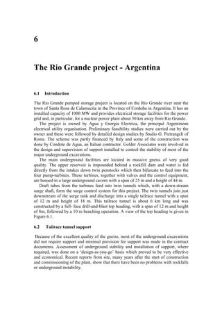
  • 3. Tailrace tunnel support 83 Figure 6.1: The 12 m span 8 m high top heading for the tailrace tunnel was constructed by full-face drill-and-blast and, because of the excellent quality of the massive gneiss, was largely unsupported. Figure 6.2: Mechanically anchored rockbolts of the type used on the Rio Grande project. These bolts were tensioned to 70% of their yield load upon installation and then, at a later stage, were re-tensioned and fully grouted.
  • 4. 84 Chapter 6: The Rio Grande project - Argentina Figure 6.3: A wedge failure in the roof of the top heading of the Rio Grande tailrace tunnel. Decisions on support were made on the basis of inspection of the excavated faces by a resident team of geotechnical engineers. Where the appearance of the face indicated that a zone of heavily jointed rock, usually associated with faulting, was being entered, the top heading was reduced to a 6 m span by 8 m high pilot tunnel to limit the volume of unstable rock which could be released from the roof. This pilot tunnel was large enough to accommodate the seven-boom jumbo, as illustrated in Figure 6.4, but small enough to limit the size of roof falls to manageable proportions. Bolting from inside the pilot heading was used to pre-support the potentially unstable wedges and blocks in the roof. In the case of the tailrace tunnel, which is itself a large excavation, the support comprised mechanically anchored and cement grouted rockbolts as illustrated in Figure 6.2, with mesh reinforced shotcrete where required. These bolts were generally installed to control the type of wedge failure illustrated in Figure 6.3. In the case of particularly large wedges, calculations of the factor of safety and support requirements were carried out on a programmable calculator, using an early version of the program UNWEDGE.
  • 5. Support for power cavern 85 Figure 6.4: A 6 m wide heading driven ahead of the tunnel face to permit pre-reinforcement of potentially unstable wedges in the roof. The seven-boom jumbo is seen working in the heading. 6.3 Support for power cavern A cross-section of the power cavern is given in Figure 6.5 and this figure includes the five main excavation stages for the cavern. Careful mapping of significant structural features in the roof and walls of the central access drive at the top of the cavern provided information for estimating potentially unstable blocks and wedges which could form in the roof of the cavern. Figure 6.6 illustrates a number of such wedges in one section of the cavern roof. At each stage of the cavern excavation, long rockbolts (up to 10 m length) were installed to stabilise wedges or blocks which had been determined as being potentially unstable. Because gneiss has usually undergone some tectonic deformation during its geological history, projection of structural features from visible exposures tends to be an imprecise process. Consequently, the potentially unstable blocks and wedges had to be reassessed after each excavation step revealed new information. The structural plan illustrated in Figure 6.6 had to be modified many times during excavation and that shown is the final plan prepared after the full cavern roof had been exposed. A general view of the cavern excavation is given in Figure 6.7. This photograph was taken when the bulk of the cavern had been completed and only a few benches in the bottom of the cavern remained to be excavated. The enlarged top of the cavern is to accommodate the overhanging crane that is supported on columns from the cavern floor. An alternative design for this cavern would have been to support the crane on concrete beams anchored to the walls as is commonly done in good quality rock.
  • 6. 86 Chapter 6: The Rio Grande project - Argentina Figure 6.5: Cavern profile and excavation stages. Figure 6.6: A plan of the traces of geological features mapped in part of the cavern roof. The shaded areas represent potentially unstable wedges requiring reinforcement.
  • 7. Discussion of support design and costs 87 Figure 6.7: A view of the 25 m span Rio Grande power cavern during excavation of the lower benches. 6.4 Discussion of support design and costs Apart from rockbolts installed to control isolated structurally controlled blocks and wedges in the roof and sidewalls and some areas of closely jointed rock which were shotcreted, the cavern was unsupported. While this was successful for this particular project, it is not the approach which should generally be used for a critical excavation such as an underground powerhouse. The damage resulting from even a small rockfall in such a cavern is out of all proportion to the savings achieved by eliminating pattern rockbolting and full shotcrete lining. Hence, in addition to the rockbolts installed to control structural instability, as described earlier, I would recommend a normal pattern of 25 mm diameter, 5 m long bolts (20% of the excavation span) on a 2.5 m grid. In addition, I would recommend the placement of 50 mm of fibre-reinforced micro-silica shotcrete
  • 8. 88 Chapter 6: The Rio Grande project - Argentina over the entire roof and upper sidewalls of the cavern. Based on current north American costs, this additional support, involving approximately 600 rockbolts and about 300 m3 of shotcrete, would have cost approximately US $200,000. In terms of the overall project cost and the increased long-term security in the cavern, this would normally be regarded as a good investment. In contrast, consider the 6 km long tailrace tunnel in which the consequences of a small rockfall are minimal. Assume that a pattern of 4 m long bolts on a 2 m grid (say 10 bolts per section) and a 50 mm shotcrete thickness had been specified for the roof and upper sidewalls of the tailrace tunnel. This would involve 30,000 bolts and 5,400 m3 of shotcrete at a total cost approaching US $5 million. This example illustrates the need to give careful consideration to the function and risks associated with each underground excavation before deciding upon the support system to be used. 6.5 Analysis using UNWEDGE program UNWEDGE, described in the previous chapter, is a user-friendly micro-computer program which can be used to analyse the geometry and the stability of wedges defined by intersecting structural discontinuities in the rock mass surrounding an underground excavation. The analysis is based upon the assumption that the wedges, defined by three intersecting discontinuities, are subjected to gravitational loading only. In other words, the stress field in the rock mass surrounding the excavation is not taken into account. While this assumption leads to some inaccuracy in the analysis, it generally leads to a lower factor of safety than that which would occur if the in situ stresses were taken into account. The application of the program UNWEDGE to the analysis of a potentially unstable wedge in the Rio Grande cavern is illustrated in the following discussion. 6.5.1 Input Data The dips and dip directions of a number of planes (maximum 20) can be entered directly into the pop-up table which appears when the ‘Input data’ option is chosen or this information can be entered in the form of a DIPS file. Once the data has been read into the program, the great circles representing the discontinuities are displayed on the screen as illustrated in Figure 6.8 and the user is prompted to select the three joint planes to be included in the analysis. Once the information on these planes has been entered, the unit weight of the rock and the shear strengths of the joints are entered. Finally, the water pressure acting on the joint surface is entered. In most cases, the default water pressure of 0 will be chosen but the user may check the sensitivity of the wedge to pore water pressure by entering appropriate values. In the case of the rock mass surrounding the Rio Grande Cavern, the dips and dip directions of the following four sets of joints are included in Figure 6.8: 1 50/131 infrequently occurring joints 2 88/225 shear joint set 3 85/264 shear joint set 4 50/345 tension joint set Joints 2, 3 and 4 form the central wedge illustrated in Figure 6.6 and these joints have been included in the analysis which follows.
  • 9. Analysis using UNWEDGE program 89 Figure 6.8: Great circles representing four joint sets which occur in the rock mass surrounding the Rio Grande cavern - imported as a DIPS file. 6.5.2 Input of excavation cross-section In setting up this analysis, the co-ordinates shown in Figure 6.9 were used to define the cavern profile. These co-ordinates must be entered sequentially and must form a closed figure. The profile is formed from straight line and arc segments and a sufficient number of co-ordinates should be entered to ensure that a smooth profile is generated. 6.5.3 Determination of wedge geometry Depending upon the shape of the cross-section, a maximum of six wedges can be formed with three intersecting joint planes. Selecting the ‘View Wedges’ option initiates the calculation which determines the shape and size of these wedges. The two wedges formed on the cavern end walls can be viewed by activating the ‘View Ends’ option. Figure 6.10 shows the wedges formed in the case of the Rio Grande power cavern for the three joint planes 2, 3 and 4 defined in Figure 6.8. The right hand bar contains information on the weight of each of these wedges, the failure mode and the calculated factor of safety. Obviously, the most dangerous wedge in this situation is the wedge formed in the roof while the wedge formed in the floor is stable and need not be considered further in this analysis.
  • 10. 90 Chapter 6: The Rio Grande project - Argentina Figure 6.9: Co-ordinates used to define the profile of the cavern. Figure 6.10: Perspective view of the wedges formed in the rock mass surrounding the Rio Grande power cavern.
  • 11. Analysis using UNWEDGE program 91 6.5.4 Installation and analysis of rockbolts The program UNWEDGE automatically determined the largest wedge which can occur in the rock mass adjacent to the excavation profile. In the case of the roof wedge, shown in Figure 6.10, the wedge extends over the full 25 m span of the cavern and weighs 11,610 tonnes. While, in exceptional circumstances, such wedges may occur, the limited extent of joints in many rock masses will restrict the size of the wedges to much smaller dimensions than those determined by UNWEDGE for the large excavations. As illustrated in Figure 6.6, the span of the central roof wedge (measured normal to the cavern axis) is about 5.5 m and the trace length of joint number 4 (50/345) is approximately 10 m. When one of the wedges is selected for more detailed analysis a ‘Size’ option is displayed and this allows the user to define the size of the wedge in terms of the area of the face on the excavation surface, the volume of the wedge, the height of the apex of the wedge or the length of one of the joint traces. In this case a trace length of 10 m is entered for the joint defined by 50/345 and the resulting wedge is illustrated in Figure 6.11. This wedge weighs 255 tonnes and will require about seven 50 tonne capacity fully grouted cables to give a factor of safety of about 1.5 which is considered appropriate for a cavern of this type. Figure 6.11: Perspective view of roof wedge in the Rig Grande cavern roof. The size of this wedge has been defined by setting the trace length of the 50/345 joint to 10 m. UNWEDGE allows the user to add a layer of shotcrete and calculates the factor of safety increase as a result of such an addition. Since the shotcrete can only be added once the surface of the wedge is fully exposed it is not taken into account in calculating the support required to stabilise the wedge. The increase in safety factor which occurs after the shotcrete has set can be regarded as a long term bonus and it does allow the user to choose a slightly lower factor of safety for the immediate support of the wedge.