Heat Exchangers by Hanif Dewan
•
91 gostaram•21,751 visualizações

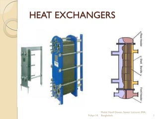
The document discusses heat exchangers used on ships. It describes that heat exchangers transfer heat from one medium to another through direct contact or a separating wall. Common applications on ships include cooling lubricating oil and fresh water using sea water, and heating fuel oil using steam. The two main types are shell and tube exchangers, where one medium flows inside tubes and the other outside the tubes, and plate exchangers, where media flow on either side of corrugated plates. Proper design and maintenance are important for heat exchanger effectiveness and service life.

Recomendados
Mais conteúdo relacionado
Mais procurados
Mais procurados (20)
Destaque
Destaque (20)
Semelhante a Heat Exchangers by Hanif Dewan
Semelhante a Heat Exchangers by Hanif Dewan (20)
Mais de Mohammud Hanif Dewan M.Phil.
Mais de Mohammud Hanif Dewan M.Phil. (20)
Último
Último (20)
Heat Exchangers by Hanif Dewan
- 1. HEAT EXCHANGERS Mohd. Hanif Dewan, Senior Lecturer, IMA, Bangladesh. 19-Apr-14
- 2. Basic Definitions: - A heat exchanger is a device built for efficient heat transfer from one medium to another, whether the media are separated by a solid wall so that they never mix, or the media are in direct contact. Or, the equipment in which transfer of heat takes place is called the heat exchanger. Mohd. Hanif Dewan, Senior Lecturer, IMA, Bangladesh. 29-Apr-14
- 3. On board ships the lubricating oil, fresh water and refrigerated gas are cooled by sea water and the fuel oil heated by steam. Heat exchangers are often used in the following applications: Liquid Cooler or Air Radiator Fuel Preheater Air conditioning evaporator and condenser steam condenser Mohd. Hanif Dewan, Senior Lecturer, IMA, Bangladesh. 39-Apr-14
- 4. Coolers On board ships, the main engine is cooled by the jacket cooling water and lubricating oil. These fluids are then passed through a cooler where sea water is used as the cooling medium to cool the fresh water and the lubricating oil. After being cooled the fluids return back to the main engine and the sea water is discharged overboard. Mohd. Hanif Dewan, Senior Lecturer, IMA, Bangladesh. 49-Apr-14
- 5. Heaters Heaters are used for various purposes on board ships.The most essential one is used for the fuel oil heating.The temperature of the fuel oil is raised by passing steam through the heating tubes and the oil on the outside of these tubes. Thus heat is transferred from the steam to the fuel oil. Mohd. Hanif Dewan, Senior Lecturer, IMA, Bangladesh. 59-Apr-14
- 6. Thermodynamic characteristics The total rate of heat transfer between the hot and cold fluids passing through a plate heat exchanger may be expressed as: Q = UA∆Tm where, U= Overall heat transfer coefficient, A= total plate area, and ∆Tm= the Log mean temperature difference. Mohd. Hanif Dewan, Senior Lecturer, IMA, Bangladesh. 69-Apr-14
- 7. Coefficient of heat transferred (U) depends on :- Type of fluid Flow condition Thermal conductivity of wall materials Thickness of the wall Cleanliness of the walls Mohd. Hanif Dewan, Senior Lecturer, IMA, Bangladesh. 79-Apr-14
- 8. Flow pattern Parallel flow Counter flow – the best thermodynamic pattern Cross flow Mixed flow – in practice use Mohd. Hanif Dewan, Senior Lecturer, IMA, Bangladesh. 89-Apr-14
- 9. Parallel flow Practically not used in marine industry May be in a combination of flow pattern (mixed flow) Inherently poorer heat transfer rates Could be found in food processing industry ADV: lower heat transfer surface temperature and more even heat transfer surface temp. Mohd. Hanif Dewan, Senior Lecturer, IMA, Bangladesh. 99-Apr-14
- 10. Counter flow Mohd. Hanif Dewan, Senior Lecturer, IMA, Bangladesh. 109-Apr-14
- 11. Cross flow Mohd. Hanif Dewan, Senior Lecturer, IMA, Bangladesh. 119-Apr-14
- 12. Mixed flow Mohd. Hanif Dewan, Senior Lecturer, IMA, Bangladesh. 129-Apr-14
- 13. Streamline flow Turbulent flow Mohd. Hanif Dewan, Senior Lecturer, IMA, Bangladesh. 139-Apr-14
- 14. Selection of Heat Exchanger Quantity of fluid to be cooled Range of temperature (inlet and outlet) to be cooled Range of fluid to be cooled as a cooling mediums (jacket water) Specific heat of medium Type of medium – corrosive or non-corrosive – safety Operating pressure Maintenance – cleaning Position in system and pipe work Cost and material Streamline (heat transfer low) or turbulent (erosion) flow Mohd. Hanif Dewan, Senior Lecturer, IMA, Bangladesh. 149-Apr-14
- 15. TYPE of HEAT EXCHANGER Consists: - i) Shell and tube type heat exchanger (Tubular or shell and tube type) ii) Plate type heat exchanger Mohd. Hanif Dewan, Senior Lecturer, IMA, Bangladesh. 159-Apr-14
- 16. Types of Heat Exchangers In the shell & tube type heat exchanger one medium flows through a set of tubes and the other medium flows on the outside.Thus heat transfer take place across the tube walls. In the plate type heat exchanger, a set of corrugated plates are tightly packed with spaces in between.The different mediums flow on either sides of the plate and heat transfer takes place across the plate. Mohd. Hanif Dewan, Senior Lecturer, IMA, Bangladesh. 169-Apr-14
- 17. Shell and tube type heat exchanger Mohd. Hanif Dewan, Senior Lecturer, IMA, Bangladesh. 179-Apr-14
- 18. Shell & Tube Type HE: 9-Apr-14 Mohd. Hanif Dewan, Senior Lecturer, IMA, Bangladesh. 18
- 19. Tubular exchangers are used in great numbers, far more than any other type of exchanger.They are made in a wide variety of sizes and styles, ranging from the tiny units used in miniature cryocoolers to giant installations containing thousands of tubes and used as condensers in base-load power stations. Tubular exchangers are so widely used because the technology is well established for making precision metal tubes capable of containing high pressures in a variety of materials.There is virtually no limit to the range of pressures and temperatures that can be accommodated. Mohd. Hanif Dewan, Senior Lecturer, IMA, Bangladesh. 199-Apr-14
- 20. Typical Materials Tubes - Aluminum brass, cupro-nickel Tube plates – Cast Naval brass Casing and water boxes – Cast iron, gunmetal Baffles – Cooper, rolled naval brass Mohd. Hanif Dewan, Senior Lecturer, IMA, Bangladesh. 209-Apr-14
- 21. Shell & Tube type HE: 9-Apr-14 Mohd. Hanif Dewan, Senior Lecturer, IMA, Bangladesh. 21
- 22. Two passage type Division plate Water box Baffle or support plate Neoprene rings Tell-tale hole Contact strip Sacrificial anode Tube stack ShellInspection door Fixed endMovable end Drain Vent Hot fluid inlet Hot fluid outlet Coolant inlet Coolant outletDistribution belt Tube plate Mohd. Hanif Dewan, Senior Lecturer, IMA, Bangladesh. 229-Apr-14
- 23. The shell (cylinder) is usually made of grained cast iron, with surfaces machined as required. Gun metal of fabricated steel may be used as alternatives depending upon requirements. Inspection doors are fitted in the distribution belts even at water box. End boxes with end access covers, are at the same material as the shell. Sacrificial anodes in rod or plug form and electrical contact strip are fitted to minimize corrosion Cont- Mohd. Hanif Dewan, Senior Lecturer, IMA, Bangladesh. 239-Apr-14
- 24. The tube stack is made up of stress relieved aluminum brass tubes expanded into Naval brass tube plates, one plate is fixed and other ended is free to allow for expansion of the stack. Brass circular baffles give radial flow to the fluid and support to the tube stack. Mohd. Hanif Dewan, Senior Lecturer, IMA, Bangladesh. 249-Apr-14
- 25. Capacity Most heat exchangers are sized to provide about 30% more surface area for heat transfer than that required.This extra allows for:- - to cope up with fouling and deposits, thereby increasing the period between opening - to cope up with the plugging of defective tubes. Usually 10% is the limit before the tube stack requires changing or the tube renewing - to cope with overloading of the engine for short period - Abnormal sea water temperature Mohd. Hanif Dewan, Senior Lecturer, IMA, Bangladesh. 259-Apr-14
- 26. BAFFLES It is important that all baffles are neat fit in the exchanger casing as by-passing of the baffles can lead to a substantial drop in efficiency. Note that casings are machined internally to allow a neat fit and that care must be taken when stripping or assembling to prevent damage The tube stack is fitted with baffles which are design to:- Mohd. Hanif Dewan, Senior Lecturer, IMA, Bangladesh. 269-Apr-14
- 27. Why ?……. Control fluid flow ensuring optimum contact between heat transfer surface and fluid Increase the time the fluid is present in the exchanger Prevent ‘coring’ in the fluid paths ( Coring occurs when a large temperature difference exists which alters the velocity of the fluid causing a heavy build-up of slow moving fluid to adhere to the tube surface) Cont- Mohd. Hanif Dewan, Senior Lecturer, IMA, Bangladesh. 279-Apr-14
- 28. Increase the surface area on the hot fluid side.This is particularly important when the fluid specific heat of the fluid (oil) is approximately haft of the cooling agent to assist in balancing the heat flow Reduce turbulence in the fluid flow to reduce the pressure drop across the exchanger Mohd. Hanif Dewan, Senior Lecturer, IMA, Bangladesh. 289-Apr-14
- 29. Type of baffle Segmental baffle Doughnut baffle Disc baffle Mohd. Hanif Dewan, Senior Lecturer, IMA, Bangladesh. 299-Apr-14
- 30. Baffle flow arrangement Segmental flow Radial flow Guide flow Axial flow Mohd. Hanif Dewan, Senior Lecturer, IMA, Bangladesh. 309-Apr-14
- 31. Causes of tube failure General wastage – over acidic water prevents the formation of a stable oxide film Impingement attack – due to turbulence Deposit attack – the metal under the deposit becomes anodic to the surrounding area and corrodes Anaerobic attack – bacteria reacts with tube material causing local attack leading to pitting or tube perforation Erosion – due to abrasive solids such as sand, or air bubble in the coolant Mohd. Hanif Dewan, Senior Lecturer, IMA, Bangladesh. 319-Apr-14
- 32. TURBULENCE Turbulence leads to erosion, pumping losses and encourages corrosion by preventing the growth of a thick oxide film. The effect on tubes of turbulence in the water boxes is usually limited to a length equal to 4 x diameter which suffer erosion It can be cause by as follow:- Cont- Mohd. Hanif Dewan, Senior Lecturer, IMA, Bangladesh. 329-Apr-14
- 33. Excessive water velocities due to overloading the heat exchanger or total blockage of a large % of tubes Partial blockage of tubes Poor design of water boxes (too shallow) Incorrect fitting of protector plates (anodes) Mohd. Hanif Dewan, Senior Lecturer, IMA, Bangladesh. 339-Apr-14
- 34. Temperature control By-passing a proportion(%) of the hot fluid By throttling the sea water flow (outlet valve) By controlling the temperature of sea water entering the heat exchanger. It is done by spilling part at the heated discharge back to the pump suction. Mohd. Hanif Dewan, Senior Lecturer, IMA, Bangladesh. 349-Apr-14
- 35. Cleaning cold fluid side (s w) Algae slimes – mechanical cleaning or flushing through with copper sulphate solution marine growth – Mechanical cleaning or chlorination Scales – soft scale by mechanical cleaning but for hard scales require circulation of an acid declare usually sulphuric acid, hydrochloric acid or citric acid in addition of inhibitors which protect the metal surface. Neutralizing solution be circulated after descaling like sodium carbonate or hydrazine. Silt, sand, rust etc – mechanical cleaning Mohd. Hanif Dewan, Senior Lecturer, IMA, Bangladesh. 359-Apr-14
- 36. Cleaning hot fluid side Fresh water creating scaling and deposits cause by corrosion or be a sludge due to the deterioration of corrosion inhibitor additive – be removed by degreasant. Oil creating oily sludge due to oxidation, carbon and contaminations were accumulate in the tube stack, thus reducing the heat transfer efficiency – be removed by either circulation of a degreasant solution or by stripping the exchanger and immersing the tube stack in a tank of cleaning solution Mohd. Hanif Dewan, Senior Lecturer, IMA, Bangladesh. 369-Apr-14
- 37. Type of degreasant Alkaline – trisodium phosphate and caustic soda Hydrocarbon solvent – trichlorothane Solvent emulsion – mixture of hydrocarbons and surfactants Mohd. Hanif Dewan, Senior Lecturer, IMA, Bangladesh. 379-Apr-14
- 38. Provision for Expansion 1. Keeping the shell, tube plates and the water- boxes or headers fixed, the tubes are allowed to expand. 2. Keeping the shell and header fixed, the entire tube stack is allowed to expand in the shell (that is, slide in the shell). 3. Keeping the tubes, tube plates and header fixed, the shell is allowed to expand or contract by means of shell expansion joint or bellows. Mohd. Hanif Dewan, Senior Lecturer, IMA, Bangladesh. 389-Apr-14
- 39. Thermal Expansion Keeping the shell, tube plate and end cover fixed while allowing the tubes to expands Fiber packing ring Metallic ring Tube plate Ferrule nut Clearance for expansion Outlet end serration Inlet end Mohd. Hanif Dewan, Senior Lecturer, IMA, Bangladesh. 399-Apr-14
- 40. Leakage tell-tale hole Rubber “O” rings Movable tube plate for free expansion Keeping the shell and header fixed, the entire tube stack is allowed to expand in the shell (that is, slide in the shell). Mohd. Hanif Dewan, Senior Lecturer, IMA, Bangladesh. 409-Apr-14
- 41. Keeping the shell, end cover and tubes while the tube plate is allowed to expands Tell-tale hole Tube plate Neoprene ring Contact strip Mohd. Hanif Dewan, Senior Lecturer, IMA, Bangladesh. 419-Apr-14
- 42. Keeping the shell, tube plates and the water-boxes or headers fixed, the tubes are allowed to expand Mohd. Hanif Dewan, Senior Lecturer, IMA, Bangladesh. 429-Apr-14
- 43. Mohd. Hanif Dewan, Senior Lecturer, IMA, Bangladesh. 439-Apr-14
- 44. Expansion arrangement Keeping the tubes, tube plates and header fixed, the shell is allowed to expand or contract by means of shell expansion joint or bellows. Mohd. Hanif Dewan, Senior Lecturer, IMA, Bangladesh. 449-Apr-14
- 45. Keeping the tubes, tube plate and end cover fixed while the shell is allowed to expanded or contracted by means of shell expansion joint – bellow type Mohd. Hanif Dewan, Senior Lecturer, IMA, Bangladesh. 459-Apr-14
- 46. LEAK TEST METHODS Water test Ultra-sonic test Fluorescein test Vacuum test Mohd. Hanif Dewan, Senior Lecturer, IMA, Bangladesh. 469-Apr-14
- 47. Water test procedure It chosen depends upon the equipment and time available even type of exchanger. It can be done by opening the water boxes and drying the tube plates. Filling the fluid space with water. for some extent, pressurize the space by compressed air for a time interval Leakages will appear or can be seen by pressure dropping. Mohd. Hanif Dewan, Senior Lecturer, IMA, Bangladesh. 479-Apr-14
- 48. Ultra-sonic test procedure Heat exchanger should be drained and any necessary access doors removed. Electrical tone generators are then place in the fluid space, care being taken to position some in the air cooling section.(use slight air pressure) The sound produced by these passes through leaks to be detected by and ultra-sonic probe moved over the tube plate (tube end) Mohd. Hanif Dewan, Senior Lecturer, IMA, Bangladesh. 489-Apr-14
- 49. Fluorescein test procedure Heat exchanger should be drained and any necessary access doors removed. Tube plates and tube should be cleaned in the normal manner Flooded up the fluid space with water containing small amount of fluorescein, thus water change to green. Then the tube plate and tubes are then illuminated by means of ultra-violet light. Any leakage will then be indicated by a fluorescent glow. After testing, cleared the parts. Mohd. Hanif Dewan, Senior Lecturer, IMA, Bangladesh. 499-Apr-14
- 50. Vacuum test procedure Heat exchanger should be drained and any necessary access doors removed. Seal each end of tube plate to prevent any ingress of air while the fluid part in vacuum. By having connection to ejectors, air in fluid space will be suck thus creating vacuum. Leak can be now detected by spreading thin sheets of polythene over the tube plates. Depressions in the sheets show the leaks even ultra-sonic probe can be use too. Mohd. Hanif Dewan, Senior Lecturer, IMA, Bangladesh. 509-Apr-14
- 51. PLATE TYPE HEAT EXCHANGER Mohd. Hanif Dewan, Senior Lecturer, IMA, Bangladesh. 519-Apr-14
- 52. A Plate Heat Exchanger , or PHE as it is more commonly called as , is a type of heat exchanger that uses metal plates instead of the conventional pipes as in a Shell and Tube Heat Exchanger . It was invented by Dr. Richard Seligman way back in 1923 . The plate heat exchanger revolutionized the concept of indirect heating or cooling of fluids . Mohd. Hanif Dewan, Senior Lecturer, IMA, Bangladesh. 529-Apr-14
- 53. Mohd. Hanif Dewan, Senior Lecturer, IMA, Bangladesh. 539-Apr-14
- 54. Mohd. Hanif Dewan, Senior Lecturer, IMA, Bangladesh. 549-Apr-14
- 55. Lateral bolts Fixed plate/ frame Plate pack Carrying bar Movable pressure plate Lateral bolts Fixed plate/ frame Guide bar Distance pieces Adjustable feet Support post Mohd. Hanif Dewan, Senior Lecturer, IMA, Bangladesh. 559-Apr-14
- 56. PLATE TYPE HEAT EXCHANGER Mohd. Hanif Dewan, Senior Lecturer, IMA, Bangladesh. 569-Apr-14
- 57. PLATE TYPE HEAT EXCHANGER Mohd. Hanif Dewan, Senior Lecturer, IMA, Bangladesh. 579-Apr-14
- 58. PLATE TYPE HEAT EXCHANGER Mohd. Hanif Dewan, Senior Lecturer, IMA, Bangladesh. 589-Apr-14
- 59. PLATE TYPE HEAT EXCHANGER Mohd. Hanif Dewan, Senior Lecturer, IMA, Bangladesh. 599-Apr-14
- 60. The above picture illustrates the construction AND liquid flow of a traditional Plate Heat Exchanger. The RED arrows represent the flow of the fluid which is hot , while the BLUE one represents the flow of the fluid which is relatively cooler. The metal plate can be either welded or semi-welded or brazen , accordingly to the industry in which the PHE is going to be incorporated into. In place of pipes passing through a chamber , we have metal chambers , usually thin in depth and seperated by gaskets . Mohd. Hanif Dewan, Senior Lecturer, IMA, Bangladesh. 609-Apr-14
- 61. PLATE TYPE HEAT EXCHANGER Mohd. Hanif Dewan, Senior Lecturer, IMA, Bangladesh. 619-Apr-14
- 62. The flow of the liquids in the PHE that the RED and BLUE fluid flow into alternating chambers.The gaskets are so designed as to allow the two fluids into successively alternating metal chambers , facilitating more surface area contact and thus , more heat transfer efficiency. Mohd. Hanif Dewan, Senior Lecturer, IMA, Bangladesh. 629-Apr-14
- 63. The Plate Type Exchanger consists of: Variable number of gasketed (titanium or stainless steel/aluminum brass) plates – clamped together between a movable pressure plate and frame by lateral bolts. Plates are suspended from upper bar and located by the lower carrying bar Plates thickness 0.6 – 0.8 mm each Plates surface are corrugated – herring bone pattern with vees pointing alternately up and down, touching in a criss-cross pattern – strength and additional heat transfer surface Mohd. Hanif Dewan, Senior Lecturer, IMA, Bangladesh. 639-Apr-14
- 64. Gasket (Nitrile rubber) bonded to the plates and arranged so that in event of failure the two fluids cannot mix Plates distance are normally 3 – 5mm Fluids enter and leave through duets or port formed in the plates corner Working pressure 14 bar, temperature as a cooler 110oC and 220oC as a heater Mohd. Hanif Dewan, Senior Lecturer, IMA, Bangladesh. 649-Apr-14
- 65. Bulkhead Single Twin frameTwin frame FRAMETYPE Mohd. Hanif Dewan, Senior Lecturer, IMA, Bangladesh. 659-Apr-14
- 66. Top slot for carrying bar Distribution area Heat transfer area Bottom slot Gasket Gasket Plate stainless steel titanium Plate relief pattern Leak channel Heat transfer area Mohd. Hanif Dewan, Senior Lecturer, IMA, Bangladesh. 669-Apr-14
- 67. WHY PLATE ARE CORRUGATED? Provided strength Increase heat transfer surface Produce turbulent flow Mohd. Hanif Dewan, Senior Lecturer, IMA, Bangladesh. 679-Apr-14
- 68. Flow pattern in plate type COUNTER FLOW Mohd. Hanif Dewan, Senior Lecturer, IMA, Bangladesh. 689-Apr-14
- 69. Maintenance of PHE: Plates – surfaces of each plates can be mechanical or chemically cleaned – care should be taken not to damaged or scratch the plates (erosion) May required replacement from time to time as per manufacturers instruction The only way to locate leaks is by visual inspection of plate surfaces Mohd. Hanif Dewan, Senior Lecturer, IMA, Bangladesh. 699-Apr-14
- 70. Advantages of PHE Titanium plates (self healing) – no corrosion or erosion risk No velocity limit (High turbulent flow) reduces risk of fouling thus increase heat transfer Easily inspection and cleaned – pipe connections are at the frame plate Compact and space saving – no head room required Risk of leakage eliminated by the gaskets arrangement Adding or removing plates can alter size and capacity Lighter in weight Damaged plates can be renewed relatively easily Easy choice of flow patterns Single frame can be used for several cooling in different fluid – central cooling Mohd. Hanif Dewan, Senior Lecturer, IMA, Bangladesh. 709-Apr-14
- 71. Disadvantages of Plate Heat Exchanger: Deteriorating gaskets are difficult to remove and bending a new joints Any scratches or markings – careless cleaning – erosion which leads to perforation of the plate and contamination Heavier than equivalent size tubular heat exchanger Temperature and pressure limitation – pressure 14 bar, temperature 110/220oC Narrow spaces between the plates can cause rapid fouling thus required frequent cleaning i) Turbulent flow causes erosion of cooper based alloy producing holes in plates, in this case contamination will occur ii) Turbulent flow causes large pressure drop Mohd. Hanif Dewan, Senior Lecturer, IMA, Bangladesh. 719-Apr-14
- 72. Advantages of Shell & Tube Type Heat Exchanger: Extended heat transfer surface possible using fins or baffles to compensate for different specific heat of the fluid Defective tubes can be easily plugged Less expansive than plate type if using the same materials Mohd. Hanif Dewan, Senior Lecturer, IMA, Bangladesh. 729-Apr-14
- 73. Disadvantages of Shell & Tube Type Heat Exchanger: Fixed size – usually 30% excess Spare tube stack may be needed Any leakage may cause contamination Difficult to clean – tube can be mechanically cleaned on inside, but outside likely to require degreasant or descalant solution. Mohd. Hanif Dewan, Senior Lecturer, IMA, Bangladesh. 739-Apr-14
- 74. Why we use the PHE instead ofTHE? - Shell and Tube Heat Exchangers cannot actually perform in par when we have a low-temperature or a low-pressure application , the design of the Plate Heat Exchanger is such that it is best suited for medium and low pressure fluids because the driving factor in the concept is surface-area. Mohd. Hanif Dewan, Senior Lecturer, IMA, Bangladesh. 749-Apr-14
- 75. As compared to shell and tube heat exchangers, the temperature approach in a plate heat exchangers may be as low as 1 °C whereas shell and tube heat exchangers require an approach of 5 °C or more. For the same amount of heat exchanged, the size of the plate heat exchanger is smaller, because of the large heat transfer area afforded by the plates (the large area through which heat can travel). Increase and reduction of the heat transfer area is simple in a plate heat-exchanger, through the addition or removal of plates from the stack. Mohd. Hanif Dewan, Senior Lecturer, IMA, Bangladesh. 759-Apr-14
- 76. Flow distribution and heat transfer equation: Design calculations of a plate heat exchanger include flow distribution and pressure drop and heat transfer. The former is an issue of Flow distribution in manifolds.A layout configuration of plate heat exchanger can be usually simplified into a manifold system with two manifold headers for dividing and combining fluids, which can be categorized into U-type and Z-type arrangement according to flow direction in the headers, as shown in manifold arrangement. Mohd. Hanif Dewan, Senior Lecturer, IMA, Bangladesh. 769-Apr-14
- 77. CENTRAL COOLING Mohd. Hanif Dewan, Senior Lecturer, IMA, Bangladesh. 779-Apr-14
- 78. Mohd. Hanif Dewan, Senior Lecturer, IMA, Bangladesh. 789-Apr-14
- 79. Central Cooling Systems These have been design for diesel engine and steam plant as per diagram shown Large sea water cooled heat exchangers, one in operation the other stand-by are the central coolers, which having excess cooling capacity to allow for fouling A controlled by pass of the fresh water to be cooled maintains it at a steady temperature of 35oC up to maximum sea water temperature of 33oC Cont - Mohd. Hanif Dewan, Senior Lecturer, IMA, Bangladesh. 799-Apr-14
- 80. Sea water temperature above 330C will result in an increase in fresh water temperature. The system is divided into low and high temperature zones. The low temperature zone contains the coolers which can be arranged in different ways to suit requirements. Automatic by-pass valves are arranged across each cooler unit which control the upstream water pressure keeping it constant irrespective of the number of coolers Mohd. Hanif Dewan, Senior Lecturer, IMA, Bangladesh. 809-Apr-14
- 81. Advantages Reduced maintenance due to the fresh water system having clean, treated water circulating. The cleaning of the system and component replacement are reduced to a minimum Fewer sea water pipes with attendant corrosion and fouling problems With titanium plate heat exchangers used in the central coolers cleaning of the coolers is simplified and corrosion reduced Cont - Mohd. Hanif Dewan, Senior Lecturer, IMA, Bangladesh. 819-Apr-14
- 82. The higher water speeds possible in the fresh water system result in reduces pipe dimensions and installation cost The number of valves made of expensive material is greatly reduced, also cheaper materials can be used throughout the fresh water system without fear of corrosion or erosion problems With a constant level of temperature being maintained, irrespective of sea water temperature, this give stability and economy of operation of the machinery – no cold starting since part of the cooling system will be in operation. Reduced cylinder liner wear, etc. Mohd. Hanif Dewan, Senior Lecturer, IMA, Bangladesh. 829-Apr-14
- 83. Disadvantages “Setting up” of the system may be difficult Leakage, causing contamination in one H/E can foul the whole system Loss of fresh water due to pipe or fitting failure will effect the whole system Mohd. Hanif Dewan, Senior Lecturer, IMA, Bangladesh. 839-Apr-14
- 84. Corrosion in Heat Exchangers: Uniform or general corrosion Galvanic or two-metal corrosion Pitting corrosion Selective leeching or de-alloying Erosion corrosion; fretting & cavitation Stress-corrosion cracking Mohd. Hanif Dewan, Senior Lecturer, IMA, Bangladesh. 849-Apr-14
- 85. Galvanic Corrosion Noble or Cathodic Platinum Gold,Titanium Silver Stainless steel Bronze/Copper/Brass Cast Iron Steel Aluminium Zinc Magnesium Active or Anodic Electrolyte Copper Zinc Mohd. Hanif Dewan, Senior Lecturer, IMA, Bangladesh. 859-Apr-14
- 86. Isolation of dissimilar metals by electrical insulation. Mohd. Hanif Dewan, Senior Lecturer, IMA, Bangladesh. 869-Apr-14
- 87. Prevention of Galvanic Corrosion Use a single material or a combination of materials that are close in the galvanic series. Avoid the use of a small ratio of anode area to cathode area. Use equal areas or a large ratio of anode to cathode area. Electrically insulate dissimilar metals where possible.This recommendation is illustrated in figure.A flanged joint is equipped with bolts contained in insulating sleeves with insulating washers under the head and nut. Paint, tape, or asbestos gasket material are alternative insulations. Local failure of the protective coating, particularly at the anode, can result in the small anode-to-cathode area syndrome marked by accelerated galvanic corrosion. Maintain all coatings in good condition, especially at the anode. Mohd. Hanif Dewan, Senior Lecturer, IMA, Bangladesh. 879-Apr-14
- 88. Decrease the corrosion characteristics of the fluid where possible by removing the corrosive agents or adding inhibitors. Avoid the use of threaded or riveted joints in favor of welded or brazed joints. Liquids or spilled moisture can accumulate in thread grooves or lap interstices and form a galvanic cell. Design for readily replaceable anodic parts or, for long life, make the anodic parts more substantial than necessary for the given stress conditions. Install a sacrificial anode lower in the galvanic series than both the metals involved in the process equipment. Mohd. Hanif Dewan, Senior Lecturer, IMA, Bangladesh. 889-Apr-14
- 89. Pitting Corrosion Pitting corrosion is the phenomenon whereby an extremely localized attack results in the formation of holes in the metal surface that eventually perforate the wall.The holes or pits are of various sizes and may be isolated or grouped very closely together. Mohd. Hanif Dewan, Senior Lecturer, IMA, Bangladesh. 899-Apr-14
- 90. Selective Leeching Selective leaching is the term used to describe a corrosion process wherein one element is removed from a solid alloy.The phenomenon occurs principally in brasses with a high zinc content (dezincification) and in other alloys from which aluminum, iron, cobalt, chromium, and other elements are removed. Grey cast iron is subject to leeching known as graphitization, whereby the iron is dissolved leaving behind a weak porous graphite network. Mohd. Hanif Dewan, Senior Lecturer, IMA, Bangladesh. 909-Apr-14
- 91. Prevention of Selective Leeching The only effective method of preventing corrosion by selective leaching is to avoid the use of materials known to be subject to it in association with the fluids concerned. Brasses with high zinc content (> 35 percent) in acid environments are particularly susceptible. Mohd. Hanif Dewan, Senior Lecturer, IMA, Bangladesh. 919-Apr-14
- 92. Erosion Corrosion Erosion corrosion is the term used to describe corrosion that is accelerated as a result of an increase in the relative motion between the corrosive fluid and a metal wall.The process is usually a combination of chemical or electrochemical decomposition or dissolution and mechanical wear action. Mohd. Hanif Dewan, Senior Lecturer, IMA, Bangladesh. 929-Apr-14
- 93. Erosion Corrosion of CondenserTubeWall Mohd. Hanif Dewan, Senior Lecturer, IMA, Bangladesh. 939-Apr-14
- 94. Prevention of Erosion Corrosion Use materials with superior resistance to erosion corrosion. Design for minimal erosion corrosion. Change the environment. Use protective coatings. Provide cathodic protection Mohd. Hanif Dewan, Senior Lecturer, IMA, Bangladesh. 949-Apr-14
- 95. Cavitation Erosion Cavitation erosion is a special class of erosion corrosion that is associated with the periodic growth and collapse of vapour bubbles in liquids. Mohd. Hanif Dewan, Senior Lecturer, IMA, Bangladesh. 959-Apr-14
- 96. Fretting Corrosion Fretting corrosion occurs at the contact points of stressed metallic joints that are subject to vibration and slight movement. It is also called friction oxidation, wear oxidation, chafing, and false brinelling. Fretting corrosion to be a special case of erosion corrosion occurring in air rather than aqueous conditions. Mohd. Hanif Dewan, Senior Lecturer, IMA, Bangladesh. 969-Apr-14
- 97. Tube-tube-sheet &Tube-baffle Fretting Mohd. Hanif Dewan, Senior Lecturer, IMA, Bangladesh. 979-Apr-14
- 98. Theories of Fretting Corrosion Mohd. Hanif Dewan, Senior Lecturer, IMA, Bangladesh. 989-Apr-14
- 99. Essential Elements for Fretting Corrosion A loaded interface.Tube-tube-sheet joints are heavily loaded by the strains induced in rolling the tubes in the tube-sheet. Vibration or repeated relative motion between the two surfaces. The load and relative motion of the interface must be sufficient to produce slip or deformation on the surfaces. Mohd. Hanif Dewan, Senior Lecturer, IMA, Bangladesh. 999-Apr-14
- 100. Prevention of Fretting Corrosion Eliminate vibration Eliminate high-stress interface Lubricate the joint Use hard surface Increase friction at the interface Use soft metallic or non-metallic interface gaskets Mohd. Hanif Dewan, Senior Lecturer, IMA, Bangladesh. 1009-Apr-14
- 101. Stress Corrosion Stress corrosion is the name given to the process whereby cracks appear in metals subject simultaneously to a tensile stress and specific corrosive media.The metal is generally not subject to appreciable uniform corrosion attack but is penetrated by fine cracks that progress by expanding over more of the surface and proceeding further into the wall. Mohd. Hanif Dewan, Senior Lecturer, IMA, Bangladesh. 1019-Apr-14
- 102. Prevention of Stress Corrosion Reducing the fluid pressure or increasing the wall thickness. Relieve residual stress by annealing. Change the metal alloy to one that is less subject to stress-corrosion cracking. E.g. carbon steel is more resistant than stainless steel to corrosion cracking in a chloride-containing environment, but less resistant to uniform corrosion. Replacing stainless steel with an alloy of higher nickel content is often effective. Mohd. Hanif Dewan, Senior Lecturer, IMA, Bangladesh. 1029-Apr-14
- 103. Modify the corrosive fluid by process treatment or the addition of corrosion inhibitors such as phosphates. Apply cathodic protection with sacrificial anodes or external power supply. Use shot peening to induce surface stress. Use venting air pockets to avoid concentration of chloride in the cooling water Mohd. Hanif Dewan, Senior Lecturer, IMA, Bangladesh. 1039-Apr-14
- 104. Cleaning & inspection For efficient heat transfer, the surface through which heat transfer take place, must be maintained clean. Coolers and heaters can loose their efficiency through accumulations of deposits like marine growths, sludge, mud, sand etc. Such deposits increase the thickness of the tubes thus affecting heat transfer.This causes greater temperature difference between the hot and cold surfaces and results in high thermal stress on the tubes. Mohd. Hanif Dewan, Senior Lecturer, IMA, Bangladesh. 1049-Apr-14
- 105. Mechanical/Chemical Cleaning Mechanical by manual and by brush Chemical by circulation Mohd. Hanif Dewan, Senior Lecturer, IMA, Bangladesh. 1059-Apr-14
- 106. Protection against Corrosion Sacrificial anodes Coating Impressed current Chemical Mohd. Hanif Dewan, Senior Lecturer, IMA, Bangladesh. 1069-Apr-14
- 107. Sacrificial Anodes Galvanic action Sacrificial anodes – aluminium, zinc, soft iron Anodes corrode away Mohd. Hanif Dewan, Senior Lecturer, IMA, Bangladesh. 1079-Apr-14
- 108. Coating Coatings – rubber, bitumen or epoxy Also use for seawater pipes Mohd. Hanif Dewan, Senior Lecturer, IMA, Bangladesh. 1089-Apr-14
- 109. Impressed Current System A technique to reduce corrosion of a metal surface by passing sufficient cathodic current to it to cause anodic dissolution rate to become negligible Cathodic protection Inert anodes – lead silver with platinum Initial use to protect the hull Mohd. Hanif Dewan, Senior Lecturer, IMA, Bangladesh. 1099-Apr-14
- 110. Ferrous Sulphate Protective film of oxide Self healing Break down if turbulence is too great Mohd. Hanif Dewan, Senior Lecturer, IMA, Bangladesh. 1109-Apr-14
- 111. Usual Causes of Tube Failure Tube & tube plate General wastage Deposit attack Anaerobic attack Erosion Mohd. Hanif Dewan, Senior Lecturer, IMA, Bangladesh. 1119-Apr-14
- 112. Protection Against Impingement Attack Mohd. Hanif Dewan, Senior Lecturer, IMA, Bangladesh. 1129-Apr-14
- 113. Cleaning & Inspection Cold fluid side ◦ Algea slimes ◦ Marine growth ◦ Silt, sand ◦ Scales Hot fluid side ◦ Sludge Mohd. Hanif Dewan, Senior Lecturer, IMA, Bangladesh. 1139-Apr-14
- 114. Alkaline Cheap Non-toxic Non-inflammable Requires heating to 70ºC to 100ºC Least efficient of the three degreasant types May attack aluminium and zinc Requires care-prevent contact with skin, eyes, etc Mohd. Hanif Dewan, Senior Lecturer, IMA, Bangladesh. 1149-Apr-14
- 115. Hydrocarbon Toxic and/or narcotic Some inflammable (except in chlorinated ones) Highly volatile - ensure good ventilation of space Use as cold liquid or vapour. More efficient than alkalis Mohd. Hanif Dewan, Senior Lecturer, IMA, Bangladesh. 1159-Apr-14
- 116. Solvent Emulsion Toxic Generally used at 50º to 60ºC May be combined with acids or alkalis to help scale removal or augment cleaning process Most efficient of the three types. Mohd. Hanif Dewan, Senior Lecturer, IMA, Bangladesh. 1169-Apr-14
- 117. Any Question? Thank you. Mohd. Hanif Dewan, Senior Lecturer, IMA, Bangladesh. 1179-Apr-14