Dc electricity
•Transferir como PPTX, PDF•
1 gostou•716 visualizações

Here you have the DC electricity Powerpoint. Enjoy it! Je, je. Podéis descargarlo y cambiar lo que queráis para aclararos mejor

Recomendados
Mais conteúdo relacionado
Mais procurados
Mais procurados (20)
Destaque
Destaque (16)
Semelhante a Dc electricity
Semelhante a Dc electricity (20)
Mais de Miguel Roca Miguel
Mais de Miguel Roca Miguel (20)
Último
Último (20)
Dc electricity
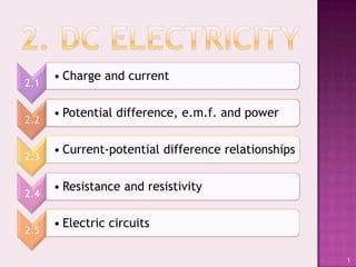
- 1. • Charge and current 2.1 • Potential difference, e.m.f. and power 2.2 • Current-potential difference relationships 2.3 • Resistance and resistivity 2.4 • Electric circuits 2.5 1
- 2. Electric Electric I=nAve charge current Definition by Understanding Definition its formula formula Different units, Units Drift velocity conversion Number of Metals, elementary semiconductors charges and insulators flowing? 2. DC Electricity 2
- 3. Electric charge is a fundamental conserved property of electrons and protons that gives rise to electrical forces Charge on protons is called positive and that on electrons is called negative All matter is made of atoms that contain protons and electrons. Charges from the same number of electrons and protons are canceled out Different number of protons and electrons make a body to be positively or negatively charged 2.1. Charge and current 3
- 4. 2.1. Charge and current 4
- 5. 2.1 Charge and current 5
- 6. Rate of flow of charge I=ΔQ/Δt • Quanity of charge flowing past a given point per unit time 2.1. Charge and current 6
- 7. 1nA=10-9A SI current unit=Ampère=A 1μA=10-6A Flow of a charge of 1A=1C/1s 1C through a given point in 1 second 1mA=10-3A 2.1. Charge and current 7
- 8. Current passing Time through flowing e Number of e 2.1. Charge and current 8
- 9. 2.1. Charge and current 9
- 10. This velocity is not that of the electromagnetic wave travelling but that of the carriers in the material where the current is passing through. It is normally very slow. Two samples of the same material but different cross sectional areas in series will have the same current passing through, so the one with the smaller area will have a higher drift velocity to compensate. Two sample with the same section but from different material in series will have the same product “nxv”. The higher number of carriers the slower drift velocity. 2.1. Charge and current 10
- 11. • n≈1028m-3 or higher • Increasing T, n remains constant, but atoms Conductors vibrate stronger and so passing current through is harder. Resistance increases. • n≈1019m-3 • Increasing T (or adding impurities), n Semiconductors increases very much and so current is easier to flow. Resistance decreases. • n≈0 Insulators • No current passes through them. (in normal conditions) 2.1. Charge and current 11
- 12. Introduction Power Potential Electrical energies power Electrical potential Relationships energy Potential difference and e.m.f. DC Electricity 12
- 13. Potential energy: Capability of a body to do workt due to its position inside a field. Gravitational Electrical potential potential energy: that energy: that which a which a mass has just charge has just for for being near a big being near a big mass that creates a charge that creates gravitational field. an electric field. (Earth) (mgΔh) (Cell) (qEΔd) 2.2.Potential difference, electromotive force and power 13
- 14. Dividing the • Potentialdifference energy of a (p.d.) charge by • Electromotive force its charge: (e.m.f.) Volt (V) • SI Unit J=CV • Relationship between units 2.2.Potential difference, electromotive force and power 14
- 15. Potential difference Electrical Other forms energy of energy Electromotive force 2.2.Potential difference, electromotive force and power 15
- 16. E=QV • From mechanics • P=VQ/Δt • Work≡Energy • Electrical • Q/Δt=I Energy P=W/Δt P=VI 2.2.Potential difference, electromotive force and power 16
- 17. P=VI E=QV P=E/Δt I=Q/Δt 2.2.Potential difference, electromotive force and power 17
- 18. P=VI Q/Δt=I V=E/Q P=VQ/Δt P=EI/Q E=VQ I/Q=1/Δt P=E/Δt 2.2.Potential difference, electromotive force and power 18
- 19. E=QV IΔt=Q V=P/I E=VIΔt E=QP/I P=VI Q/I=Δt E=PΔt 2.2.Potential difference, electromotive force and power 19
- 20. V=E/Q PΔt=E Q=IΔt V=PΔt/Q V=E/(IΔt) 1/I=Δt/Q E=PΔt V=P/I 2.2.Potential difference, electromotive force and power 20
- 21. Q=IΔt E/P=Δt I=P/V Q=IE/P Q=PΔt/V 1/V=I/P PΔt=E Q=E/V 2.2.Potential difference, electromotive force and power 21
- 22. I=Q/Δt P/E=1/Δt Q=E/V I=PQ/E I=E/(VΔt) 1/V=Q/E E/Δt=P I=P/V 2.2.Potential difference, electromotive force and power 22
- 23. Δt=Q/I V/P=1/I Q=E/V Δt=QV/P Δt=E/(VI) E=QV VI=P Δt=E/P 2.2.Potential difference, electromotive force and power 23
- 24. Introduction I-V graphs Resistance Ohmic materials Tungsten Ohm’s law filament lamps Semiconductors diodes DC Electricity 24
- 25. Resistance It can be The resistance defined as the of an electrical quotient component is a between the R=V/I measure of its potential Unit “Ohm” (Ω) opposition to an difference Ω=VA-1 electric current across it and flowing in it the current through it 2.3. I-V Relationships 25
- 26. Under certain conditions, current is proportional to the potential difference V/I is constant, so R is constant Components that obey Ohm’s law are called “ohmic components” Ohm’s law≠Resistance 2.3. I-V Relationships 26
- 27. I-V graphs show how current behaves when voltage varies. Knowing that “V=IR” we can realise that “I/V=1/R” The “gradient”(slope) for a point in these graphs shows the value for “1/R” at its certain conditions. The bigger the gradient the lower resistance. The smaller the gradient the higher resistance. 2.3. I-V Relationships 27
- 28. Ohmic components: Resistors Tungsten Semiconductors Conductors filament lamps diodes (under certain conditions) 2.3. I-V Relationships 28
- 29. Conductors. (In normal conditions) • Constant slope means constant resistance. 2.3. I-V Relationships 29
- 30. Conductors. • For values of V close to zero, normal conditions. So, (almost)constant slope and (almost)constant resistance. • For values of V far from zero, T increases and resistance increases (as we saw from I=nAve). Then slope gets smaller 2.3. I-V Relationships 30
- 31. Semiconductors. (under special configuration) • For negative values of V, no current is allowed to pass through, so I=0. • For positive values of V, (as semiconductor has impurities) n⇈ and so resistance decreases. Hence the gradient increases 2.3. I-V Relationships 31
- 32. 2.3. I-V Relationships 32
- 33. Resistance Resistivity Material Resistor property Power dissipated Units by a resistor DC Electricity 33
- 34. • Every electrical component, no matter its function, has a certain resistance. (R=V/I) • Those components that have no other purpose than make current harder to pass through it are called “resistors”. Resistors are usually symbolised by… 2.4. Resistance and resistivity 34
- 35. P=VI I=V/R V=IR P=V2/R P=I2R I2=V2/R2 Every component in a circuit will dissipate power (energy per unit time) This power can be shown in these 3 different ways For a resistor, the more power it dissipates the higher temperature it gets 2.4. Resistance and resistivity 35
- 36. Two wires of the same material Wire1 (Resistance=R1) Wire1 has length l and a cross section area A Wire2 (Resistance=R2) Wire2 has length l2>l and cross section area A R2>R1 R∝l The longer the resistor, the higher resistance 2.4. Resistance and resistivity 36
- 37. Two wires of the same material Wire1 (Resistance=R1) Wire1 has length l and a cross section area A Wire2 (Resistance=R2) Wire2 has length l and cross section area A2>A The wider the resistor, R2<R1 R∝1/A the lower resistance 2.4. Resistance and resistivity 37
- 38. Two wires of different materials Wire1 (Resistance=R1) Wire1 has length l and a cross section area A Wire2 (Resistance=R2) Wire2 has length l and cross section area A R depends R2≠R1 on material 2.4. Resistance and resistivity 38
- 39. R=(constant)x(l/A) This constant is a property of the material and is called resistivity (ρ) ρ=RA/l so units for resistivity ρ≡Ωm Resistivity is different for each material (bigger for insulators, smaller for conductors) Resistivity in a material changes depending on conditions 2.4. Resistance and resistivity 39
- 40. Increasing temperature, terms in I=nAve are affected as follows: Conductor Semiconductor n constant n⇈ Exponential increase of charge carriers A constant A constant Because of the lattice vibrations v ↓ v↓ Because of the lattice vibrations e constant e constant I∝v I↓ I↑ I∝nv So R↑ So R↓ In a conductor, resistivity increases if temperature increases Conductors have a positive temperature coefficient In a semiconductor, resistivity decreases if temperature increases Semiconductors have a negative temperature coefficient (NTC) NTC resistors are called thermistors. Symbolised by 2.4. Resistance and resistivity 40
- 41. Conductor Resistor R Thermistor R Positive Temperature Coefficient Negative Temperature Coefficient (PTC) (NTC) The great dependence with temperature of thermistors makes them very useful as temperature sensors 2.4. Resistance and resistivity 41
- 42. Circuit Cells Applications components Using Components Internal voltmeters and table resistance ammeters Conservation of energy and Resistors Solar cells charge in configurations circuits Potential divider DC Electricity 42
- 43. Cell, battery (longer=positive) Resistor (Conductor) Diode In every (semiconductor) component will be Variable resistor a potential (can vary from 0 to R) difference fall Thermistor when current (NTC) passes through it Filament Lamp (dissipates much heat) Ammeter (R≈0) Voltmeter (R≈∞) 2.5. Electric circuits 43
- 44. Cell Component 1 Component 2 Component 3 Energy Energy Energy Electrical dissipated dissipated dissipated energy by by by converted in component component component the cell 1 2 3 This means, in terms of energy per unit charge: ε= Vi= Iri Electromotive force of the cell=sum of potential difference in every component 2.5. Electric circuits 44
- 45. For every point in a circuit, the current “in” must be the same as the current “out” Ii→ A Io→ For every single wire, the For point A Ii=Io current passing through it will be constant I2→ I1→ I1→ For point A I1=I2+I3 A B I3→ For point B I2+I3=I1 VA-VB is the same for both wires 2.5. Electric circuits 45
- 46. An ideal cell would give all the electric energy converted without dissipate any at all This is, in fact, not possible. Real cells loose energy by themselves The real value of the potential difference given by a cell is shown as: V=ε-Ir Where ε is the electromotive force given by the cell, I is the current passing through it and r is known as internal resistance 2.5. Electric circuits 46
- 47. V=ε-Ir Connecting the cell directly to a voltmeter will give a reading of ε because the high resistance of the voltmeter will make I≈0 and then V≈ε Connecting the cell in series with a resistor will give a reading different to ε due to the presence of a current flowing through the internal resistance. A reading≠0 2.5. Electric circuits 47
- 48. Repeating the readings for several different resistances (a variable resistance can be used to do this) will allow us to get a V-I graph that will look like: ε V I As the straight line must obey the equation V=ε-Ir, the y intercept will show ε and the gradient will show -r 2.5. Electric circuits 48
- 49. Efficiency (E) of a component is defined as the quotient between the energy given by it and the energy needed to give it For a cell we can express this as E=V/ε But we saw before that V decreases in a cell when current increases Efficiency of a cell decreases when current increases To get a good efficiency of a cell we must take care about “r” of the cell being very lower than the resistance in the circuit (so the effect of “r” will be very small) 2.5. Electric circuits 49
- 50. These are a special kind of cells, also called photovoltaic, made of a semiconductor material They work following the photoelectric effect e.m.f. of these cells are constant (as normal cells) Internal resistance in solar cells is only constant for low intensities For larger intensities, internal resistance increases significally 2.5. Electric circuits 50
- 51. In order to measure the current passing through a component an ammeter has to be connected in series with it To measure the voltage fall in a component we should connect a voltmeter in parallel with it •As resistance of the ammeter is very close to zero, does not affect the current passing through and does not dissipate energy •As resistance in the voltmeter is very large (≈∞), it does not affect current passing through the resistor as it is in parallel with an infinite resistance Readings in A and V in this configuration will show the current and voltage of the resistor 2.5. Electric circuits 51
- 52. Resistors in series: is equivalent to R1 R2 R=R1+R2 Resistors in parallel: R1 is equivalent to R=R1xR2/(R1+R2) R2 For combinations of more than 2 resistors, just join two of them in a equivalent one and go on step by step 2.5. Electric circuits 52
- 53. From conservation of energy in circuits we know that referring to the next configuration: VA-B VB-C VC-D V If we connect wires A and B (or any other pair) to another circuit, in fact, we are performing a new cell with a lower potential difference Different values for the resistors will arrange different voltage values (always lower than V) An “ideal” potential divider will allow us to take any possible voltage value between 0 and V This kind of potential divider can be done with a variable resistor 2.5. Electric circuits 53
- 54. There are two kinds of variable resistors Rheostats: Potentiometers: Resistor can be Three-terminal changed but it has variable resistor only two terminals 2.5. Electric circuits 54
- 55. This is the configuration for a potentiometer that allow to obtain all the possible V voltage values by a potential divider Connecting any component to VOUT we can vary the voltage on 0≤VOUT≤V it in all the range 2.5. Electric circuits 55