1. 1
1. Model geometry
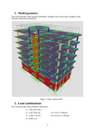
This section provides model geometry information, including items such as joint coordinates, joint
restraints, and element connectivity.
Figure 1: Finite element model
2. Load combinations
This section provides load combination information.
1) 1.2D+1.6L+0.5Lr
2) 1.2D+1.6Lr+f1L (f1=1 for L.L=100 psf)
3) 1.32D+1.1E+f1L (F1=0.5 for L.L<100 psf)
4) 0.99D+1.1E
2. 2
2.1. Load Definitions
Table 1.1: Load Case Definitions
Table 1.1 Load Case Definitions
Case Type Initial Cond Modal Case Base Case
DEAD Linear Static Zero
MODAL Linear Modal Zero
LIVE Linear Static Zero
EQX Linear Static Zero
EQY Linear Static Zero
FINISHES Linear Static Zero
E. DEAD Linear Static Zero
PARTITION Linear Static Zero
WINDX Linear Static Zero
WINDY Linear Static Zero
2.2. Static case load assignments
Table 1.2: Case - Statics - Load Assignments
Table 1.2: Case - Static - Load Assignments
Case Load Type Load Name Load SF
DEAD Load pattern DEAD 1.000
LIVE Load pattern LIVE 1.000
EQX Load pattern EQX 1.000
EQY Load pattern EQY 1.000
FINISHES Load pattern FINISHES 1.000
E. DEAD Load pattern E. DEAD 1.000
PARTITION Load pattern PARTITION 1.000
WINDX Load pattern WINDX 1.000
WINDY Load pattern WINDY 1.000
2.3. Load Combination Definitions
Table 1.3: Combination Definitions
Table 1.3: Combination Definitions
Combo Name Combo Type Case Name Scale
Factor
SERVICE Linear Add DEAD 1.000000
SERVICE LIVE 1.000000
SERVICE PARTITION 1.000000
SERVICE FINISHES 1.000000
SERVICE E. DEAD 1.000000
ULTIMATE Linear Add DEAD 1.200000
ULTIMATE LIVE 1.600000
ULTIMATE PARTITION 1.200000
ULTIMATE FINISHES 1.200000
ULTIMATE E. DEAD 1.200000
COMB1 Linear Add DEAD 1.320000
COMB1 LIVE 0.550000
3. 3
Table 1.3: Combination Definitions
Combo Name Combo Type Case Name Scale
Factor
COMB1 EQX 1.100000
COMB1 FINISHES 1.320000
COMB1 PARTITION 1.320000
COMB1 E. DEAD 1.320000
COMB1-1 Linear Add DEAD 1.320000
COMB1-1 LIVE 0.550000
COMB1-1 EQX -1.100000
COMB1-1 FINISHES 1.320000
COMB1-1 PARTITION 1.320000
COMB1-1 E. DEAD 1.320000
COMB2 Linear Add DEAD 1.320000
COMB2 LIVE 0.550000
COMB2 EQY 1.100000
COMB2 FINISHES 1.320000
COMB2 PARTITION 1.320000
COMB2 E. DEAD 1.320000
COMB2-1 Linear Add DEAD 1.320000
COMB2-1 LIVE 0.550000
COMB2-1 EQY -1.100000
COMB2-1 FINISHES 1.320000
COMB2-1 PARTITION 1.320000
COMB2-1 E. DEAD 1.320000
COMB3 Linear Add DEAD 0.990000
COMB3 EQX 1.100000
COMB3 FINISHES 0.990000
COMB3 PARTITION 0.990000
COMB3 E. DEAD 0.990000
COMB3-1 Linear Add DEAD 0.990000
COMB3-1 EQX -1.100000
COMB3-1 FINISHES 0.990000
COMB3-1 PARTITION 0.990000
COMB3-1 E. DEAD 0.990000
COMB4 Linear Add DEAD 0.990000
COMB4 EQY 1.100000
COMB4 FINISHES 0.990000
COMB4 PARTITION 0.990000
COMB4 E. DEAD 0.990000
COMB4-1 Linear Add DEAD 0.990000
COMB4-1 EQY -1.100000
COMB4-1 FINISHES 0.990000
COMB4-1 PARTITION 0.990000
COMB4-1 E. DEAD 0.990000
COMB5 Linear Add DEAD 1.200000
COMB5 LIVE 0.500000
COMB5 WINDX 1.000000
COMB5 FINISHES 1.200000
COMB5 PARTITION 1.200000
4. 4
Table 1.3: Combination Definitions
Combo Name Combo Type Case Name Scale
Factor
COMB5 E. DEAD 1.200000
COMB5-1 Linear Add DEAD 1.200000
COMB5-1 LIVE 0.500000
COMB5-1 WINDY 1.000000
COMB5-1 FINISHES 1.200000
COMB5-1 PARTITION 1.200000
COMB5-1 E. DEAD 1.200000
3. Load patterns
This section provides loading information as applied to the model.
3.1. Definitions
Table 2.1: Load Pattern Definitions
Table 2.1: Load Pattern Definitions
Load Pattern Design Type Self-Wt.
Multiplier
Auto Load
DEAD DEAD 1.000000
LIVE LIVE 0.000000
EQX QUAKE 0.000000 UBC97
EQY QUAKE 0.000000 UBC97
FINISHES SUPER DEAD 0.000000
E. DEAD SUPER DEAD 0.000000
PARTITION SUPER DEAD 0.000000
WINDX WIND 0.000000 UBC97
WINDY WIND 0.000000 UBC97
Table 2.2: Load Assignment Definitions
Table 2.2: Load Assignment Definitions
Load Pattern Design Type Load Direction
psf
LIVE LIVE 80.00 GRAVITY
FINISHES SUPER DEAD 32.00 GRAVITY
E. DEAD SUPER DEAD 30.00 GRAVITY
PARTITION SUPER DEAD 20.00 GRAVITY
3.2. Auto wind loading
Table 2.3: Auto Wind - UBC97
Table 2.3: Auto Wind - UBC97
LoadPat Angle windward
Cq
Leeward
Cq
Max Z Min Z Wind
Speed
Exposur
e
I
Degrees in in mph
WINDX 0.000 0.800000 0.500000 918.000 180.000 80.00 C 1.00000
5. 5
Table 2.3: Auto Wind - UBC97
LoadPat Angle windward
Cq
Leeward
Cq
Max Z Min Z Wind
Speed
Exposur
e
I
Degrees in in mph
WINDY 90.000 0.800000 0.500000 907.200 180.000 80.00 C 1.00000
3.3. Auto seismic loading
Table 2.4: Auto Seismic - UBC97
Table 2.4: Auto Seismic - UBC97
Load Pat Dir Percent
Ecc
Ct Max Z Min Z R Soil Type
in in
EQX X 0.050000 0.035000 918.000 180.000 5.500000 SC
EQY Y 0.050000 0.035000 918.000 180.000 5.500000 SC
Table 2.5: Auto Seismic - UBC97
Table 2.5: Auto Seismic - UBC97
Load Pat Z Ca Cv Source
Type
Source
Dist.
Na Nv
km
EQX 0.2 0.240000 0.320000 B 0.00 1.300000 1.600000
EQY 0.2 0.240000 0.320000 B 0.00 1.300000 1.600000
Table 2.6: Auto Seismic - UBC97
Table 2.6: Auto Seismic - UBC97
LoadPat I T Used Weight
Used
Base Shear Ft Used
Sec Kip Kip Kip
EQX 1.000000 0.6685 5099.530 443.832 0.000
EQY 1.000000 0.5779 5099.530 513.404 0.000
4. Material properties
This section provides material property information for materials used in the model.
4.1. Basic Mechanical Properties
Table 3.1: Material Properties - Basic Mechanical Properties
Table 3.1: Material Properties - Basic Mechanical Properties
Material Unit Weight Unit Mass E1 G12 U12 A1
Kip/in3 Kip-s2/in4 Kip/in2 Kip/in2 1/F
3000Psi 8.6806E-05 2.2483E-07 3122.02 1300.84 0.200000 5.5000E-06
4000Psi 8.6806E-05 2.2483E-07 3605.0 1502.08 0.200000 5.5000E-06
A615Gr60 2.8356E-04 7.3446E-07 29000.0 6.5000E-06
6. 6
4.2. Concrete Data
Table 3.2: Material Properties - Concrete Data
Table 3.2: Material Properties – Concrete Data
Material Fc
Kip/in2
3000Psi 3.000
4000Psi 4.000
4.3. Rebar Data
Table 3.3: Material Properties - Rebar Data
Table 3.3: Material Properties - Rebar Data
Material Fy Fu
Kip/in2 Kip/in2
A615Gr60 60.000 90.000
5. Section properties
This section provides section property information for objects used in the model.
5.1. Frame Section Properties
Table 4.1: Frame Section Properties
Table 4.1: Frame Section Properties
Section Name Material Shape t3 t2 Area Torsion
Const.
I33 I22
in in in2 in4 in4 in4
B 18X24 3000Psi Rectangular 24.0000 18.0000 432.00 25192.3 20736.0 11664.0
B18X18 3000Psi Rectangular 18.0000 18.0000 324.00 14784.1 8748.00 8748.00
B12X18 3000Psi Rectangular 12.0000 18.0000 216.00 6085.12 5832.00 2592.00
Col 18X18 4000Psi Rectangular 18.0000 18.0000 324.00 14784.1 8748.00 8748.00
Col 18X12 4000 psi Rectangular 18.0000 12.0000 216.00 6085.12 5832.00 2592.00
Table 4.2: Frame Section Properties
Table 4.2: Frame Section Properties
Section Name AS2 AS3
in2 in2
B 18X24 360.00 360.00
B18X18 270.00 270.00
B18X12 180.00 180.00
Col 18X18 270.00 270.00
Col 18X12 180.00 180.00
Table 4.3: Frame Section Properties
Table 4.3: Frame Section Properties
Section Name S33 S22 Z33 Z22 R33 R22
in3 in3 in3 in3 in in
B 18X24 1728.00 1296.00 2592.00 1944.00 6.9282 5.1962
B18X18 972.00 972.00 1458.00 1458.00 5.1962 5.1962
B18X12 648.00 432.00 972.00 648.00 5.1962 3.4641
Col 18X18 972.00 972.00 1458.00 1458.00 5.1962 5.1962
Col 18X12 648.00 432.00 972.00 648.00 5.1962 3.4641
7. 7
Table 4.4: Frame Section Properties
Table 4.4: Frame Section Properties
Section Name A Mod A2Mod A3Mod J Mod I2Mod I3Mod M Mod W Mod
B 18X24 1.00000 1.00000 1.00000 1.00000 1.00000 1.00000 1.00000 1.00000
B18X18 1.00000 1.00000 1.00000 1.00000 1.00000 1.00000 1.00000 1.00000
B18X12 1.00000 1.00000 1.00000 1.00000 1.00000 1.00000 1.00000 1.00000
Col 18X18 1.00000 1.00000 1.00000 1.00000 1.00000 1.00000 1.00000 1.00000
Col 18X12 1.00000 1.00000 1.00000 1.00000 1.00000 1.00000 1.00000 1.00000
Table 4.5: Frame Section Properties - Concrete Column
Table 4.5: Frame Section Properties
Section
Name
Rebar MatL Rebar MatC Reinf
Config
Lat
Reinf
Cover NumBars
3Dir
NumBars
2Dir
in
Col 18X18 A615Gr60 A615Gr60 Rectangular Ties 1.5000 VARIES VARIES
Col 18X12 A615Gr60 A615Gr60 Rectangular Ties 1.5000 VARIES VARIES
Table 4.6: Frame Section Properties - Concrete Column
Table 4.6: Frame Section Properties - Concrete Column
Section Name Bar Size
L
Bar Size
C
Spacing
C
NumCBar
s2
NumCBar
s3
in
Col 18X18 #8 #3 8.0000 VARIES VARIES
Col 18X12 #8 #3 8.0000 VARIES VARIES
Table 4.7: Frame Section Properties - Concrete Beam
Table 4.7: Frame Section Properties - Concrete Beam
Section Name Rebar MatL Rebar MatC Top Cover Bot Cover
in in
B 18X24 A615Gr60 A615Gr60 1.5000 1.5000
B18X18 A615Gr60 A615Gr60 1.5000 1.5000
B18X12 A615Gr60 A615Gr60 1.5000 1.5000
5.2. Areas Section Properties
Table 4.8: Area Section Properties
Table 4.8: Area Section Properties
Section Material Area Type Type Drill DOF Thickness Bend
Thick
F11Mod
in in
R.WALL 3000Psi Shell Shell-Thin Yes 9.0000 8.0000 1.000000
S1 3000Psi Shell Shell-Thin Yes 6.0000 6.0000 1.000000
STAIR SLAB 3000Psi Shell Shell-Thin Yes 6.0000 6.0000 1.000000
WALL 3000Psi Shell Shell-Thin Yes 9.0000 9.0000 1.000000
8. 8
Table 4.9: Area Section Properties
Table 4.9: Area Section Properties
Section F22Mod F12Mod M11Mod M22Mod M12Mod V13Mod V23Mod M Mod
R.WALL 1.000000 1.000000 1.000000 1.000000 1.000000 1.000000 1.000000 1.000000
S1 1.000000 1.000000 1.000000 1.000000 1.000000 1.000000 1.000000 1.000000
STAIR
SLAB
1.000000 1.000000 1.000000 1.000000 1.000000 1.000000 1.000000 1.000000
WALL 1.000000 1.000000 1.000000 1.000000 1.000000 1.000000 1.000000 1.000000
Table 4.10: Area Section Properties
Table 4.10: Area Section
Properties,
Section W Mod
R.WALL 1.000000
S1 1.000000
STAIR SLAB 1.000000
WALL 1.000000
6. Soil Report Data
After the study of bore logs and soil report, it is recommended to adopt RAFT foundation at minimum
6’-0” depth from the lower road level with the safe allowable bearing capacity of 2.30 Tsf. Depth of
foundation can be increased to any desired depth as per requirement conservatively with the same
bearing value as recommended above. The value for Modulus of subgrade reaction is 22080 lb/ft3
.
In accordance with soil report and location of proposed building, the structure is to be constructed in
ZONE 2B with intermediate moment resisting frame (IMRF).