
Recomendados
Recomendados
Mais conteúdo relacionado
Semelhante a Patente de Nicola Tesla Us511916
Semelhante a Patente de Nicola Tesla Us511916 (20)
Último
Último (20)
Patente de Nicola Tesla Us511916
- 1. (No Model.) 2 Sheets-Sheet 1. N. TESLA. ELECTRIC GENERATOR. No. 511,916. Patented Jan. 2,1894. I ' - l J ' I . [F IE’ 3! . / TWO 1 (I! K B’ .M’ I M HIl , J 1 I K 1 P 7 0 V H 7H? 0 Q ‘ JV . G’ A _ _=-_ ‘i _E__ E a I c’ A D .P a “lxhmeom ' I ~ I awqmboz' " W WM M NNNNNNNNNNNNN‘mouum counmv. > wAwm'rou. 0. c4
- 2. (No Model.) 2 Sheets-Sheet 2. 11.1mm. ELECTRIC GENERATOR. No. 511,916. Patented Jan. 2,1894. * @J- 2 El WW/LGOOGO _ fhweutoz we umloxu. umcmmhwm co:AAAAAAv,
- 3. 20 25 35 45 50 UNITED STATES PATENT ‘OFFICE. NIKOLA TESLA, OF NEIV YORK, N. Y. ELECTRIC G EN ERATO R. SPECIFICATION forming part of Letters Patent No. 511,916, dated January 2,‘ 1894. Application ?led August 19,1893. Serial No. 483,562. (No model.) To all whont it may concern. Be it known that I, NIKOLA TESLA, a citizen of the United States, residing at New York,in the county and State of New York, have in vented certain new and useful Improvements in Electric Generators, of which the follow ing is a speci?cation, reference being had to the drawings accompanying and forming a part of the same. In an application of even date herewith, Serial No. $3,563, I have shown and described a form of engine invented by me, which, un der the in?uence of an applied force such as the elastic tension of steam or a gas under pressure, yields an oscillation of constant period. . In order that my present invention may be more readily understood I will explain the conditions which are to be observed in order to secure this result. It is a well known mechanical principle that it‘ a spring possessing a sensible inertia be brought under tension, as by being stretched, and then freed, it will perform vi brations which are isoehronous, and as to period, in the main, dependent upon the ri gidity of the spring, andits own inertia or that of the system of which it may form an imme diate part. This is known to-be true in all cases where the force which tends to bring the spring or movable system into a given position is proportionate to the displacement. In the construction of my engine above re ferred to I have followed and applied this principle, that is to say, I employ a cylinder and a piston which in any suitable manner I maintain in reciprocation by steam or gas under pressure. To the moving piston or to the cylinder, in case the latter rec1proeate and the piston remain stationary, a spring is connected so as to be maintained in vibration thereby, and whatever may be the inertia of the piston or of the moving system and the rigidity of the spring relatively to each other, provided, the practical limits within which the law holds true that the forces whichtend to bring the moving system to a given'position are proportionate to the displacement, are not exceeded, the impulses of the power impelled piston and the natural vibrations of the spring will always correspond in direction and coin cide in time. In the case of the engine referred to,the ports are so arranged that the movement of the piston within the cylinder in either di rection ceases when the force tending to impel it and the momentum which it has acquired are counterbalanced by the increasing press ure of the steam or compressed air in that end of the cylinder toward which it is moving, and as in its movement the piston has shut oif at a given point, the pressure that impelled itand established the pressure that tends to return it, it is then impelled in the opposite direction, and this action is continued as long as the requisite pressure is applied. The length of the stroke will vary with the pressure, but the rate or period of reciprocation is no more dependent upon the pressure applied to drive the piston, than would be the period of oscil lation of a pendulum permanently maintained in vibration, upon the force which periodically impels it, the effectot variations in such force being merely to produce corresponding varia tions in the length of stroke or amplitude of vibration respectively. In practice I have found that the best re sults are secured by the employment of an airy spring, that is, a body of con?ned air or gas which is compressed and rare?ed by the movements of the piston, and in order to se cure a spring of constant rigidity I prefer to employ a separate chamber or cylinder con taining air at the normal atmospheric press ure, although it might be at any other press ure, and in which works a plunger connected with or carried by the piston rod. The main reason why no engine heretofore has been capable of producing results of this nature is that it has been customary to connect with the reciprocating parts a heavy fly-wheel or some equivalent rotary system of relatively very great inertia, or in other cases where no rotary system was employed, as in certain re ciprocating engines or tools, no regard has been paid to the obtainment of the conditions essential to the end which I have in View, nor would the pressure of such conditions in said devices appear to’ result in any special advantage. Such an engine as I have described affords a means for accomplishing a result heretofore unattained, the continued production of elec tric currents of constant period, by impart ing the movements of the piston to a core or 55 65 75 85 9O 95
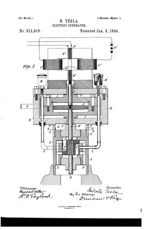
- 4. 511,916 . coil in a magnetic ?eld. It should be stated however, that in applying the engine for this purpose certain conditions are encountered which should be taken into consideration in order to satisfactorily secure the desired re sult. When a conductor is moved in a mag netic ?eld and a current caused to circulate therein,theelectro-magneticreaction between it and the ?eld, might disturb the mechanical oscillation to such an extent as to throw it out of isochronism. This, forinstan‘ce, might occur when. the electro-magnetic reaction is verygreat in comparison tothepowerof the en-' gine, and there is'a retardation of the current so that the electromagnetic reaction might have an effect similar to that which would re sult from a variation of the tension of the _ spring, but if the circuit of the generator be 20 25 35 45 55 65 so adjustedthat the phases of the electromo .tive force and current coincide .in time, that is to say, when the current is not retarded, then the generator driven by the engine acts merely as a frictional resistance and will not, as a rule, alter the period of the mechanical vibration, although it may varyits amplitude. This condition may be readily secured by properly proportioning the self induction and capacity of the circuit including the genera tor. 'I have, however, observed the further fact in connection with the use of such en gines as a means for running a generator, that it is advantageous that the period of the engineand the natural period of electrical vibration of the generator should be the same, as in such case-"thebestconditions for electri cal resonance are established and the possi bility of disturbing the period of mechanical vibrations is reduced to a minimum. Ihave found that even if the theoretical conditions necessary for maintaining a constantperiod in the engine itself are not exactly maintained, still the engine and generator combined will vibrate at a constant period. For example, if instead of usingin the engine an independent cylinder and plunger, as an air spring of prac tically constant rigidity, I cause the piston to impinge upon air cushions at the ends of its own cylinder, although the rigidity of such . cushions or springs might be considerably af fected and Varied by thevariations of pressure within the cylinder, still by combining with such an engine a generator which has a period of its own approximately that of the engine, constant vibration may be maintained even through a considerable range of varying press ure, owing to the controlling action of the electro-magnetic system. I have even found that under certain conditions the in?uence of the electromagnetic system may be made so great as to entirely control the period of the mechanical vibration within wide limits of varying pressure. This is likely to occur in those instances where the power of the en gine while fully capable of maintaining a vibration once started, is not sufficient to change its rate. So, for the sake of illustra tion, if a pendulum is started in vibration, 1 and a small force applied periodically in the‘ _ ‘ proper direction to maintain it in motion, this force would have no substantial control over the period of the oscillation, unless the in ertia of the pendulum be small inlcomparison to the impelling force, and this would be true no matter through what fraction of the period the force may be applied. . ' In the case under consideration the engine is merely an agent for maintaining the vibration once started, although it will be understood that this does not preclude the performance of useful work which would simply result in a shortening of the stroke. My invention, therefore, involves the combination of a piston free to recipro cate under the in?uence of steam or a gas under pressure and the movableelement of e an electric generator which is in direct me chanical connection with the piston, and it is more especially the, object of my invention to secure from such combination electric cur-' rents of a constant period. In the attainment of this object I have found it preferable to construct the engine so that it of itself con trols the period, but as I have stated before‘, I may so modify the elements of the combi nation that the electro-magnetic system may exert a partial or even complete control of the period. _ I In‘illustration oflthe manner in which the invention is carried‘ out I now refer to the accompanying drawings. Figure l is a central sectional .view of an engine and generator embodying the inven tion. Fig. 2 is a modification of the same. Referring to Fig. 1 A is the‘main cylinder in which works a piston B. Inlet ports C 0 pass through the sides of the cylinder open ing at the middle portion thereof and on oppo< site sides. Exhaust ports D D extend through the walls of the cylinder and are formed with branches that open into the interiorof the cylinder on each side of the inlet ports and on opposite sides of the cylinder. The piston B is formed with two circumferential grooves E F which communicate through openings G in the piston with-the cylinder on opposite sides of said piston respectively. The particular construction of the cylinder, the piston and the ports controlling it may be very much varied, and is not in itself ma-' terial, except that in the special case now un— der consideration it is .desirable that all the ports, and more especially the exhaust ports should be made very much larger than is usu ally the case so that no force due to the ac tion of the steam or compressed air will tend to retard or a?ect the return of the piston in either direction. The piston B is secured to a piston rod H which works in suitable stu? ing boxes in the heads of the cylinder A. This rod is prolonged on one side and extends through bearings V in a cylinder I suitably mounted or supported in line‘with the ?rst, and within which is a disk or plunger J car ried by the rod H. The cylinder I is without ports of any kind and is air-tight except as a 70 75 80 90 95 [CO [05 IIO H5 [20 125 13:
- 5. IO 20 25 35 45 55 60 511,916 small leakage may occur through the bear ings V, which experience has shown need not be ?tted with any very considerable ac curacy. The cylinder I is surrounded by a jacket K which leaves an open space or cham ber around it. The bearings V in the cylin der I, extend through the jacket K to the out side air and the chamber between the cylin der and jacket is made steam or air-tight as by a suitable packing. The main supply pipe L for steam or compressed air leads into this chamber, and the two pipes that lead to the cylinder A run from the said chamber, oil cups M being conveniently arranged to de liver oil into the said pipes for lubricating the piston. In the particular form of engine shown, the jacket K which contains the cylin der I is provided with a flange N by which it is screwed to“ the end of the cylinder A. small chamber 0 is thus formed which has air vents P in its sides and drip pipes Q leading out from it through which the oil which col lects in it is carried off. To explain now the operation of the engine described,in the position of the parts shown, or when the piston is at the middle point of its stroke, the plunger J is at the center of the cylinder I and the air on both sides of the same is at the normal pressure of the outside atmosphere. It a source of steam or com pressed air be then connected to the inlet ports 0 O of the cylinder A and a movement be imparted to the piston as by a sudden blow, the latter is caused to reciprocate in a man ner well understood. The movements of the piston compress and rarefy the air in the cyl inder I at opposite ends of the same alter nately. A forward stroke compresses the air ahead of the plunger J which acts as a spring to return it. Similarly on the back strdke the air is compressed on the opposite side of the plunger J and tends to drive it forward. The compressions of the air in the cylinder I and the consequent loss of energy due mainly to the imperfect elasticity of the air, give rise to a very considerable amount of heat. This heat I utilize by conducting the steam or com pressed air to the engine cylinder through the chamber formed by the jacket surrounding the air-spring cylinder. The heat thus taken up and used to raise the temperature of the steam or air acting upon the piston is availed of to increase the e'liiciency of the engine. In any given engine of this kind the normal pressure will produce a stroke of determined length, and this will be increased or dimin ished according to the increase of pressure above or the reduction of pressure below the normal. In constructing the apparatus proper allow ance is made for a variation in the length of stroke by giving to the con?ning cylinder I of the air spring properly determined dimen sions. The greater the pressure upon the , piston, the higher the degree of compression of the air-spring, and the consequent coun» teracting force upon the plunger. The rate or period of reciprocation of the piston, how ever, is mainly determined as described above by the rigidity of the air spring and the in ertia of the moving system, and anylperiod of oscillation within very wide limits may be secured by properly portioning these factors, as by varying the dimensions of the air cham ber which is equivalent to varying the rig idity of the spring, or by adjusting the weight of the moving parts. These conditions are all readily determinable, and an engine con structed as herein described may be made to follow the principle of operation above stated and maintain a perfectly uniform period through very wide limits of pressure. The pressure of the air con?ned in the cyl inder when the plunger I is in its central po~ sition will always be practically that of the surrounding atmosphere, for while the cylin der is so constructed as 'not to permit such sudden escape of air as to sensibly impair or modify the action of the air spring there will still be a slow leakage of air into or out of it around the piston rod according to the press ure therein, so that the pressure of the air on opposite sides of the plunger will always tend to remain at that of the outside atmosphere. To the piston rod II is secured a conductor or coil of wire D’ which by the movements of the piston is oscillated in the magnetic ?eld produced by two magnets B’ B’ which may be permanent magnets or energized by coils G’ 0’ connected with a source of continuous currents E’. The movement of the coil D’ across the lines of force established by the magnets gives rise to alternating currents in the coil. These currents, if the period of mechanical oscillation be constant will be of constant period, and may be utilized for any purpose desired. In the case under consideration it is as sumed as a necessary condition that the in ertia of the movable element of the genera tor and the electro-maguetic reaction which it exerts will not be of such character as to materially disturb the action of the engine. Fig. 2 is an example of a combination in which the engine is not of itself capable of determining entirely the period of oscillation, but in which the generator contributes to this end. In this ?gure the engine is the same as in Fig. 1. The exterior air spring is however omitted and the air spaces at the ends of the cylinder A relied on for accomplishing the same purpose. As the pressure in these spaces is liable to variations from variations in the steam or gas used in impelling the pis~ ton they might affect the period of oscillation, and the conditions are not as stable and cer tain as in the case of an engine constructed as in Fig. 1. But if the natural period of vi bration of the elastic system be made to ap proximately accord with the average period of the engine such tendencies to variation are very largely overcome and the engine will preserve its period even through a consid erable range of variations of pressure. The 70 75 85 95 I00 IIO 115 I20 125 130
- 6. IO 20 25 35 generator in this case is composed of a mag netic casing F’ in which a laminated core G’ secured to the piston rod H is caused to vi brate. Surrounding the plunger are two ex citing coils O' O’, and one or more induced coils D’ D’. The coils ‘C’ O’ are connected with a generator of continuous currents E’ and are wound to produce consequent poles in the core G’. Any movement of the latter will therefore shift the lines of force through coils D’ D’ and produce currents therein. In the circuit of coils D’ is shown a con denser H’; It need only be said that by the use of a proper condenser the self induction of this circuit may be neutralized. Such‘a circuit will have a certain natural period of vibration, that is to say that when the elec tricity therein is disturbed in any way an electrical or electromagnetic vibration of‘a certain period takes place, and as this de pends upon the capacity and self induction, such period may be varied to approximately accord with the period of the engine. ' In case the power of the engine be com‘ paratively small, as when the pressure is ap plied through a very small fraction of the total stroke, the electrical vibration will tend to control the period, and it is clear that if the character of such vibration be not very widely different from the average period of vibration of the engine under ordinary work ing conditions such control may be entire ly adequate to produce the desired results. Having now described my invention, what I claim is— 1. The combination with the piston or equiv alent element of an engine which is free to reciprocate under the action thereon of steam or a gas under pressure, of the moving con ductor or element of an electric generator in direct mechanical connection therewith. 2. The combination with the piston or equiv alent element of an engine which is free to reciprocate under the action of steam or a gas 511,916 under pressure, of the moving conductor or element of an electric generator in direct me chanical connection therewith, the engine and generator being adapted by their relative ad justment with respect to period to produce currents of constant period, as set forth. 3. The combination with an engine compris ing a piston which is free to reciprocate un der the action of steam or a gas under press ure, and an electric generator having induc ing and induced elements one of which is ca pable of oscillation in the ?eld of force, the said movable element being carried by the piston rod of the engine, as set forth. 4. The combination with an engine oper ated by steam or a gas under pressure and hav ing a constant period of reciprocation, of an electric generator, the moving element of which is carried by the reciprocating part of the engine, the generator and its circuit be ing so related to the engine with respect to the period of electrical vibration as not to disturb the period of the engine, as set forth. 5. The combination with'a cylinder and a piston reciprocated by steam- or a gas under pressure of a spring maintained in vibration by the movement of the piston, and an elec tric generator, the movable conductor or ele ment of which is connected with the piston, these elements being constructed and adapt ed in the manner set forth for producing a current of constant period. 6. The method of producing electric cur rents of constant period herein described which consists in imparting the oscillations of an engine to the moving element of an elec tric generator and regulating the period of mechanical oscillation by an adjustment of the reaction of the electric generator, as here in set forth. NIKOLA TESLA.Witnesses: PARKER W. PAGE, R. F. GAYLORD. 45 . 51° 55 65 75