El último vuelo del discovery
•
1 gostou•1,920 visualizações

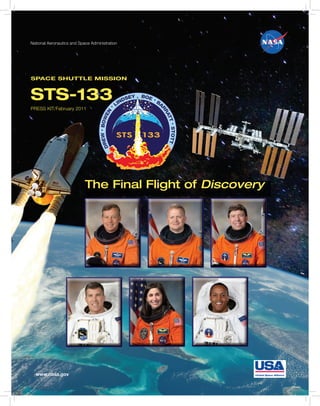
24.02.2011-El transbordador espacial Discovery despegó a las 4:53 pm hora del este jueves desde el Centro Kennedy de la NASA en Florida, con el comandante Steve Lindsey líder de la tripulación STS-133 para entregar el Módulo Permanente multipropósito y Robonaut 2 a la estación espacial.

Recomendados
Recomendados
Mais conteúdo relacionado
Mais procurados
Mais procurados (15)
Destaque
Semelhante a El último vuelo del discovery
Semelhante a El último vuelo del discovery (20)
Mais de Jaume Satorra
Mais de Jaume Satorra (20)
Último
Último (20)
El último vuelo del discovery
- 1. National Aeronautics and Space Administration SPACE SHUTTLE MISSION STS-133 PRESS KIT/February 2011 The Final Flight of Discovery www.nasa.gov
- 3. CONTENTS Section Page MISSION OVERVIEW ............................................................................................................... 1 TIMELINE OVERVIEW .............................................................................................................. 9 MISSION PROFILE ................................................................................................................... 11 MISSION OBJECTIVES ............................................................................................................ 13 MISSION PERSONNEL ............................................................................................................. 15 DISCOVERY CREW .................................................................................................................. 17 PAYLOAD OVERVIEW .............................................................................................................. 25 P E RMA N E NT M UL T IP U RP OS E M OD UL E . . . . . . . . . . . . . . . . . . . . . . . . . . . . . . . . . . . . . . . . . . . . . . . . . . . . . . . . . . . . . . . . . . . . . . . . . . . . . . . . . . . . . . . . . . . . . . . . 25 E X P R ES S L OG I S TI CS CA RR I ER 4 . . . . . . . . . . . . . . . . . . . . . . . . . . . . . . . . . . . . . . . . . . . . . . . . . . . . . . . . . . . . . . . . . . . . . . . . . . . . . . . . . . . . . . . . . . . . . . . . . . .. . . . . . 31 R O B ON A UT 2 . . . . . . . . . . . . . . . . . . . . . . . . . . . . . . . . . . . . . . . . . . . . . . . . . . . . . . . . . . . . . . . . . . . . . . . . . . . . . . . . . . . . . . . . . . . . . . . . . . . . . . . . . . . . . . . . . . . .. . . . . . . . . . . . . . . . . . . 34 RENDEZVOUS & DOCKING ....................................................................................................... 37 U N D O CK I NG , S E PA RA TI O N A N D D EPA RTU R E . . . . . . . . . . . . . . . . . . . . . . . . . . . . . . . . . . . . . . . . . . . . . . . . . . . . . . . . . . . . . . . . . . . . . . . . . . . . . . . . . . . . . . . 38 SPACEWALKS ......................................................................................................................... 39 EXPERIMENTS ......................................................................................................................... 45 S H OR T- D UR AT I O N EXP ER IM E NT S T O B E P E R FO RM E D O N STS-133 . . . . . . . . . . . . . . . . . . . . . . . . . . . . . . . . . . . . . . . . . . . . . . . . . . . . . 45 R E S EA R CH SAM PL E S/H ARD WA R E T O BE D E L I V E R ED T O S TAT I O N O N D I S C O VER Y . . . . . . . . . . . . . . . . . . . . . . . . . . . . . . 47 R E S EA R CH SAM PL E S/H ARDWA R E T O BE R E T UR N E D O N D I S C O VER Y . . . . . . . . . . . . . . . . . . . . . . . . . . . . . . . . . . . . . . . . . . . . . . . . . . 51 SPACE SH UTTLE DETAILED TEST OBJECTIVES (DTO) AND DETAILED SUPPLEMENTARY OBJECTIVES ( D S O ) . . . . . . . . . . . . . . . . . . . . . . . . . . . . . . . . . . . . . . . . . . . . . . . . . . . . . . . . . . . . . . . . . . . . . . . . . . . . . . . . . . . . . . . . . . . . . . . . . . . . . . . . . . . . . .. . . . . . . . . . . . . . . . 54 HISTORY OF SPACE SHUTTLE DISCOVERY ............................................................................. 59 SHUTTLE REFERENCE DATA .................................................................................................... 63 FEBRUARY 2011 CONTENTS i
- 4. Section Page LAUNCH AND LANDING ........................................................................................................... 81 L A U N CH . . . . . . . . . . . . . . . . . . . . . . . . . . . . . . . . . . . . . . . . . . . . . . . . . . . . . . . . . . . . . . . . . . . . . . . . . . . . . . . . . . . . . . . . . . . . . . . . . . . . . . . . . . . . . . . . . . . . . . . .. . . . . . . . . . . . . . . . . . . . . . . 81 A B OR T T O OR B IT . . . . . . . . . . . . . . . . . . . . . . . . . . . . . . . . . . . . . . . . . . . . . . . . . . . . . . . . . . . . . . . . . . . . . . . . . . . . . . . . . . . . . . . . . . . . . . . . . . . . . . . . . . . . . . . .. . . . . . . . . . . . . . . . . 81 T RA N SA TLA NT I C A BOR T L A N D I NG . . . . . . . . . . . . . . . . . . . . . . . . . . . . . . . . . . . . . . . . . . . . . . . . . . . . . . . . . . . . . . . . . . . . . . . . . . . . . . . . . . . . . . . . . . . . . . . . . . .. . . 81 R E T UR N TO L A UNCH SIT E . . . . . . . . . . . . . . . . . . . . . . . . . . . . . . . . . . . . . . . . . . . . . . . . . . . . . . . . . . . . . . . . . . . . . . . . . . . . . . . . . . . . . . . . . . . . . . . . . . . . . . . . .. . . . . . . . . . . 81 A B OR T O N C E A RO U N D . . . . . . . . . . . . . . . . . . . . . . . . . . . . . . . . . . . . . . . . . . . . . . . . . . . . . . . . . . . . . . . . . . . . . . . . . . . . . . . . . . . . . . . . . . . . . . . . . . . . . . . . . . . . .. . . . . . . . . . . . 81 L A N D I NG . . . . . . . . . . . . . . . . . . . . . . . . . . . . . . . . . . . . . . . . . . . . . . . . . . . . . . . . . . . . . . . . . . . . . . . . . . . . . . . . . . . . . . . . . . . . . . . . . . . . . . . . . . . . . . . . . . . . . . .. . . . . . . . . . . . . . . . . . . . . . 81 ACRONYMS AND ABBREVIATIONS ......................................................................................... 83 MEDIA ASSISTANCE ............................................................................................................... 97 PUBLIC AFFAIRS CONTACTS .................................................................................................. 99 ii CONTENTS FEBRUARY 2011
- 5. MISSION OVERVIEW At NASA’s Kennedy Space Center in Florida, space shuttle Discovery is poised for the STS-133 launch from Launch Pad 39A following the roughly six-hour journey, known as “rollout,” from the Vehicle Assembly Building to the pad. Image credit: NASA/Jim Grossmann As space shuttle Discovery heads to the 4:50 p.m. EST on Thursday, Feb. 24. The International Space Station on its final mission, flight is designated Utilization and Logistics it will be taking with it two key components – Flight 5 (ULF5) in the assembly sequence of the Italian-built Permanent Multipurpose the space station. Module (PMM) and Express Logistics Carrier 4 (ELC4) – that will provide spare parts and The commander for Discovery’s final flight storage capacity to the orbiting complex. is veteran astronaut Steve Lindsey (Col., Discovery also will deliver Robonaut 2, which USAF, Retired). He will be joined by will become the first humanoid robot in space. Pilot Eric Boe (Col., USAF) and Mission Specialists Steve Bowen (Capt., U.S. Navy), The 39th flight of NASA’s most flown shuttle is Dr. Michael Barratt, Nicole Stott and scheduled to last 11 days, beginning at Alvin Drew (Col., USAF Retired). FEBRUARY 2011 MISSION OVERVIEW 1
- 6. While seated at the commander’s station, NASA astronaut Steve Lindsey, STS-133 commander, participates in a post insertion/deorbit training session in the crew compartment trainer in the Space Vehicle Mock-up Facility at NASA’s Johnson Space Center. Lindsey is wearing a training version of his shuttle launch and entry suit. Lindsey has flown four times before, including supporting the target launch window. Bowen twice on Space Shuttle Discovery. He was pilot is a veteran of two shuttle flights, STS-126 in on STS-95, where Senator John Glenn served as November 2008 and STS-132 in May 2010, and a payload specialist. Lindsey also commanded has conducted five spacewalks. Bowen will STS-121, a return to flight mission in July 2006. join Drew on the two planned spacewalks of the STS-133 mission. Boe previously served as the pilot of STS-126 in November 2008, which delivered a number of Discovery will spend two days heading toward supplies and new equipment to the station. its rendezvous with the International Space Drew flew on STS-118 in August 2007, which Station. On the second day of the flight, the delivered a piece of the station’s truss structure. crew will perform the standard scan of the Barratt and Stott are previous residents of the shuttle’s thermal protection system using the International Space Station. Barratt served as a orbiter boom sensor system attached to the end member of Expeditions 19 and 20 and Stott of Discovery’s robotic arm. While the served as a member of Expeditions 20 and 21, inspection is underway, Bowen, Drew and Stott all in 2009. will work on preparing the spacesuits onboard the shuttle that will be transferred to the station On Jan. 19, Bowen replaced Tim Kopra as the after docking and will be used during the STS-133 mission specialist 2 following a bicycle mission’s two spacewalks. injury Jan. 15 that prohibited Kopra from 2 MISSION OVERVIEW FEBRUARY 2011
- 7. Dr. Michael Barratt assists fellow STS-133 Mission Specialist Steve Bowen during spacewalk training at the Neutral Buoyancy Laboratory in Houston. On the third day of the flight, Discovery will of the starboard truss, right next to where the approach and dock with the space station. Alpha Magnetic Spectrometer will be installed After the hatches are opened between the two on STS-134. That mission also will deliver spacecraft, both crews will begin working on ELC3, which will be the final logistics carrier transferring items between the two vehicles. installed on the station. It will be positioned on Before the end of the day, Barratt and Stott will the upper outboard attachment point on the use the station’s robotic arm to retrieve ELC4 port side. from inside the shuttle’s payload bay and install it in the lower inboard position on the Flight day 4 will be focused on more transfer starboard side of the station’s truss structure. work, as well as preparations by Bowen and The cargo carrier weighs 8,235 pounds. ELC1 Drew for their spacewalk the next day. Both and 2 were placed on the station’s truss crews will walk through the choreography of structure during STS-129. ELC1 is mounted on the spacewalk, and both Bowen and Drew will the lower inboard position on the port side of spend the night camped out inside the Quest the station. ELC2 is on the upper outboard side airlock. FEBRUARY 2011 MISSION OVERVIEW 3
- 8. The main activity for flight day 5 will be the camera wedge, which will allow access to the spacewalk itself. While outside, Bowen and external camera that is mounted on the Drew will install a power extension cable that starboard side of the station. This camera is could be used between Unity and Tranquility in located very close to where ELC4 will be the event Tranquility ever loses power. It needs installed, and to allow enough clearance for to be installed before the PMM is secured future spare parts to be loaded onto the carrier, in place because of access to the work area. this wedge will tilt the camera stanchion out of They will move the failed ammonia pump that the way. Also, Bowen and Drew will install Doug Wheelock and Tracy Caldwell Dyson two rail stubs, which are small extensions on removed during Expedition 24 from its the end of the station’s mobile transporter rail. temporary stowage location on the station’s These stubs will allow the mobile transporter to mobile base structure to External Stowage travel the entire length of the rail with the crew Platform 2, which is on the side of the Quest and equipment translation aid (CETA) cart airlock. The two spacewalkers will install a attached, and reach all of the work sites. NASA astronaut Alvin Drew, STS-133 mission specialist, participates in a spacesuit fit check in the Space Station Airlock Test Article in the Crew Systems Laboratory at NASA’s Johnson Space Center. Astronaut Nicole Stott, mission specialist, assists Drew. 4 MISSION OVERVIEW FEBRUARY 2011
- 9. For both spacewalks, Bowen will be designated carry 14 racks to the station – an experiment extravehicular crew member 1 (EV1), and will rack, six resupply stowage platforms, five wear the suit bearing red stripes. Drew, who resupply stowage racks and two integrated will be making his first two spacewalks on stowage platforms. STS-133, will be extravehicular crew member 2 (EV2) and will wear the unmarked suit. Among the items tucked away inside the PMM, is Robonaut 2, known as R2. Although its Flight day 6 will be focused on the installation primary job for now is demonstrating to of the PMM. The PMM is about the same engineers how dexterous robots behave in size as the Columbus laboratory and is also space, the hope is that, through upgrades and known as Leonardo, one of the multi-purpose advancements, it could one day venture outside logistics modules. It was modified to become a the station to help spacewalkers make repairs permanent module attached to the International or additions to the station or perform scientific Space Station. Once in orbit, the PMM will work. Once R2 is unpacked, likely several offer 2,472 additional cubic feet of pressurized months after it arrives, it will be initially volume for stowage and for scientific use. operated inside the Destiny laboratory for Barratt and Stott will operate the station’s operational testing, but over time, both its robotic arm to install the PMM on the earth- territory and its applications could expand. facing side of the Unity node. The PMM will There are no plans to return R2 to Earth. NASA astronaut Michael Barratt, STS-133 mission specialist, shakes hands with Robonaut 2 (R2) during media day in the Space Vehicle Mock-up Facility at NASA’s Johnson Space Center. Ron Diftler, NASA Robonaut project manager, is at left. FEBRUARY 2011 MISSION OVERVIEW 5
- 10. Flight day 7 will include the second and final covers from the Tranquility node. Also, the spacewalk of the mission. Drew and Bowen spacewalkers will troubleshoot the radiator will be the spacewalkers once again and will grapple stowage beams located on the port side focus on removing thermal covers from the of the station. This is being done in advance of express pallet carrier assembly on ELC4. some spare radiator panels that will arrive at Bowen will remove a light-weight adapter plate the station in the future. assembly from the Columbus module and will install a new version of that payload bracket. Flight days 8 and 9 will be spent completing Drew will reconfigure the starboard CETA cart transfer work between Discovery and the space and will install a new light fixture on it. Bowen station. The crews will also enjoy some will install a new camera pan and tilt unit on off-duty time prior to Discovery’s undocking, the Dextre robot and will remove thermal which will take place on flight day 10. Attired in a training version of his shuttle launch and entry suit, NASA astronaut Eric Boe, STS-133 pilot, occupies the pilot’s seat during a simulation exercise in the motion-base shuttle mission simulator in the Jake Garn Simulation and Training Facility at NASA’s Johnson Space Center. 6 MISSION OVERVIEW FEBRUARY 2011
- 11. Once Discovery undocks from the station, Boe Flight day 11 will be spent checking out the will fly the shuttle in a final victory lap around reaction control system (RCS) jets and the flight the International Space Station complex. The control surfaces. Both of these systems will be shuttle crew will take detailed photographs of put through their paces to ensure that they are the external structure of the station, which ready to support Discovery’s landing. The RCS serves as important documentation for the jets will be used during the early part of entry, ground teams in Houston to monitor the up until the atmosphere builds up enough for orbiting laboratory. Once the loop of the the flight control surfaces to take over and steer station is finished, Discovery will fire its the shuttle toward the runway. engines to take it away from the vicinity of the station. That same day, the crew will complete Discovery is scheduled to land on flight day 12 the late inspection of the shuttle’s heat shield to at the Kennedy Space Center in Florida. At the ensure that nothing was damaged during the time of its landing, Discovery will have traveled docked phase of the mission. more than 143 million miles over the course of 26 years in service to the nation and the world. Space Shuttle Discovery lands on Runway 33 at the Shuttle Landing Facility at NASA’s Kennedy Space Center in Florida at 9:08 a.m. (EDT) on April 20, 2010, completing the 15-day STS-131 mission to the International Space Station. FEBRUARY 2011 MISSION OVERVIEW 7
- 12. External Tank Repairs Engineers completed modifications to 99 of the 108 stringers using a technique known as a During Discovery’s launch attempt on Nov. 8, “radius block modification,” which provides 2010, small cracks were found on the shuttle’s added structural support in areas known to external tank mid-section, known as the carry much of the structural load of the external intertank, specifically on the tops of two tank. These radius blocks essentially fit over 21-foot-long, U-shaped aluminum brackets, existing stringer edges through which the called stringers. Four additional small securing rivets are installed to provide cracks were found on three stringers during additional structural support. Engineers also thorough X-ray of the backside of the tank modified the five stringers where cracks were after Discovery was returned to the Vehicle found with a “doubler” that adds additional Assembly Building before Christmas. support to the repaired part of the stringer. 8 MISSION OVERVIEW FEBRUARY 2011
- 13. TIMELINE OVERVIEW Flight Day 1 • Docking to Harmony/pressurized mating adapter 2 • Launch • Hatch opening and welcoming • Payload bay door opening • Canadarm2 grapple of Express Logistics • Ku-band antenna deployment Carrier 4 (ELC4) cargo pallet, handoff to • Shuttle robotic arm activation and payload shuttle robotic arm, and handoff back to bay survey Canadarm2 for installation on the starboard 3 lower inboard attachment system • Umbilical well and handheld external tank photo and TV downlink Flight Day 4 Flight Day 2 • Cargo transfer • Discovery’s thermal protection system • OBSS handoff from Canadarm2 to shuttle survey with shuttle robotic arm/orbiter robotic arm boom sensor system (OBSS) • Spacewalk tool preparation • Extravehicular mobility unit, or spacesuit, • Spacewalk 1 preparations by Bowen and checkout Drew • Centerline camera installation • Spacewalk 1 procedure review • Orbiter docking system ring extension • Spacewalk 1 campout by Bowen and Drew • Orbital maneuvering system pod survey in the Quest airlock • Rendezvous tools checkout Flight Day 5 Flight Day 3 • Spacewalk 1 by Bowen and Drew (J612 power extension cable installation from • Rendezvous with the International Space Unity to Tranquility, transfer of failed pump Station module from the payload attachment • Rendezvous pitch maneuver photography of bracket on the mobile base system to Discovery’s thermal protection system by external stowage platform 2, installation of a Expedition 26 crew members Paolo Nespoli wedge for camera port 3 and installation of and Cady Coleman starboard crew equipment and translation aid (CETA) cart rail stubs) FEBRUARY 2011 TIMELINE OVERVIEW 9
- 14. Flight Day 6 • Crew off-duty time • Installation of the Permanent Multipurpose • Rendezvous tools checkout Module (PMM) to the nadir, or Earth-facing, • Farewells and hatch closure port of Unity • Centerline camera installation • Focused inspection of Discovery’s thermal protection heat shield, if required Flight Day 10 • Spacewalk 2 preparations by Bowen and • Discovery’s final undocking from station and Drew fly-around • Spacewalk 2 procedure review • Final separation from the station • Spacewalk 2 campout by Bowen and Drew • OBSS late inspection of Discovery’s thermal in the Quest airlock heat shield Flight Day 7 • OBSS berth • PMM ingress and internal outfitting Flight Day 11 • Spacewalk 2 by Bowen and Drew (removal • Cabin stowage of thermal insulation from the ELC4, • Flight control system checkout installation of CETA lights, troubleshooting of the port 1 truss radiator stowage beam • Reaction control system hot-fire test bracket, removal and replacement of a cargo adapter plate on Columbus, installation of a • Deorbit preparation briefing pan and tilt unit on a camera on Dextre and • Ku-band antenna stowage removal of thermal covers) Flight Day 12 Flight Day 8 • Deorbit preparations • Cargo transfer to station from the PMM • Payload bay door closing • Crew off duty time • Deorbit burn Flight Day 9 • Discovery’s final landing at KSC • Reconfiguration of spacewalk equipment • Joint crew news conference 10 TIMELINE OVERVIEW FEBRUARY 2011
- 15. MISSION PROFILE CREW Space Shuttle Main Engines: Commander: Steve Lindsey SSME 1: 2044 Pilot: Eric Boe SSME 2: 2048 Mission Specialist 1: Alvin Drew SSME 3: 2058 Mission Specialist 2: Steve Bowen External Tank: ET-137 Mission Specialist 3: Michael Barratt SRB Set: BI-144 Mission Specialist 4: Nicole Stott RSRM Set: RSRM-112 LAUNCH SHUTTLE ABORTS Orbiter: Discovery (OV-103) Abort Landing Sites Launch Site: Kennedy Space Center, RTLS: Kennedy Space Center Shuttle Launch Pad 39A Landing Facility Launch Date: Feb. 24, 2011 TAL: Primary – Zaragoza, Spain Launch Time: 4:50 p.m. EST (preferred Alternates – Morón, Spain and in-plane launch time for Istres, France Feb. 24) AOA: Primary – Kennedy Space Center Launch Window: 10 Minutes Shuttle Landing Facility Altitude: 122 Nautical Miles Alternate – White Sands Space (140 Miles) orbital insertion; Harbor 190 nautical miles (218 statute miles) LANDING rendezvous Inclination: 51.6 degrees Landing Date: March 7, 2011 Duration: 10 days, 18 hours, 59 minutes Landing Time: 11:50 a.m. EST Primary landing Site: Kennedy Space Center VEHICLE DATA PAYLOADS Shuttle Liftoff Weight: 4,525,220 pounds Express Logistics Carrier 4 (ELC4) Orbiter/Payload Liftoff Weight: 268,620 Permanent Multipurpose Module (PMM) pounds Orbiter/Payload Landing Weight: 204,736 pounds Software Version: OI-34 FEBRUARY 2011 MISSION PROFILE 11
- 16. This page intentionally blank 12 MISSION PROFILE FEBRUARY 2011
- 17. MISSION OBJECTIVES 1. Rendezvous and dock space shuttle 8. Activate and check out PMM (this is the Discovery to the International Space Station nominally planned activation). pressurized mating adapter 2 and perform mandatory safety briefing for all crew − Activate PMM systems. members. − Ingress PMM. 2. Robotically install Express Logistics Carrier − Install one portable fire extinguisher 4 (ELC4) to starboard three truss lower and one portable breathing apparatus inboard common attach site. in PMM. 3. Robotically install Permanent Multipurpose 9. Perform daily space station payload status Module (PMM) to Unity node nadir or checks, as required. Earth-facing port. 10. Transfer oxygen from the orbiter to the 4. PMM activities: Perform minimal station airlock high pressure gas tanks; activation and checkout to preserve module 25 pounds minimum. and cargo (if only a short time allowed for PMM activation, do enough to ensure the 11. Transfer nitrogen from the orbiter to the PMM survival. However, nominal timeline station airlock high pressure gas tanks; will allow full activation). Perform passive 25 pounds minimum. common berthing mechanism sealing surface inspection. 12. Transfer remaining cargo items per flight ULF5 TPL. 5. Activate ELC4. 13. Perform daily middeck activities to support 6. Transfer and stow critical items per payloads (status checks). Utilization and Logistics Flight 5 (ULF5) transfer priorities list (TPL). 14. Perform space station payload research operations tasks. 7. Complete spacewalk tasks to support station operations. There are also several 15. Complete camera port 3 (CP3) camera other spacewalk tasks deemed to fit within calibration, checkout and survey after the the existing spacewalk timelines; however, CP3 wedge is installed (spacewalk task), they may be deferred if the spacewalk is and downlink data for analysis. behind schedule. The spacewalk will not be extended to complete these tasks. FEBRUARY 2011 MISSION OBJECTIVES 13
- 18. 16. Perform intravehicular activity tasks: − Perform SDTO 13005-U, ISS structural life validation and extension during − Install recycle filter tank assembly. ULF5 orbiter undocking (IWIS highly desired). − Remove and replace Tranquility node atmosphere revitalization rack carbon 23. Perform payloads of opportunity (not dioxide removal assembly bed. required during docked ops) if propellant available. 17. Transfer water from orbiter to space station per flight ULF5 TPL. − Ram Burn Observations 2 (RAMBO-2). 18. Reboost the space station with the orbiter if − Maui Analysis of Upper Atmospheric mission resources allow and are consistent Injections (MAUI). with station trajectory analysis and planning. − Shuttle Exhaust Ion Turbulence Experiments (SEITE). 19. Perform imagery survey of the space station exterior during orbiter fly-around after − Shuttle Ionospheric Modification with undock. Pulsed Local Exhaust (SIMPLEX). 24. Perform program-approved spacewalk 20. Perform checkout of ELC4. get-ahead tasks. These tasks do not fit in 21. Perform Developmental Test Objective the existing spacewalk timelines; however, (DTO) 701b (DragonEye Flash Light the spacewalk team will be trained and Intensification Detection and Ranging). ready to perform them should the opportunity arise. The spacewalk 22. Perform structural SDTOs (Station operations team in mission control has the Developmental Test Objective) as follows: flexibility to select the tasks to be completed based on efficiencies gained in performing − Perform SDTO 13005-U, ISS structural the already scheduled required tasks. life validation and extension, during ULF5 orbiter docking. 25. Perform program approved interior get-ahead tasks. These tasks do not fit in − Perform SDTO 13005-U, ISS structural the existing timelines; however, the life validation and extension, during operations team and crew will be trained PMM installation (ISS wireless and ready to perform should the instrumentation system (IWIS)) opportunity arise. required. 26. Perform imagery of space station’s Russian − Perform SDTO 13005-U, ISS structural segment exterior for historical life validation and extension, during documentation. ULF5 mated reboost (IWIS required). 14 MISSION OBJECTIVES FEBRUARY 2011
- 19. MISSION PERSONNEL KEY CONSOLE POSITIONS FOR STS-133 Flt. Director CAPCOM PAO Ascent Richard Jones Charlie Hobaugh Josh Byerly Barry Wilmore (Wx) Orbit 1 (Lead) Bryan Lunney Steve Robinson Josh Byerly Orbit 2 Ginger Kerrick Megan McArthur Pat Ryan Planning Rick LaBrode Mike Massimino Brandi Dean Entry Tony Ceccacci Charlie Hobaugh Josh Byerly Barry Wilmore (Wx) Shuttle Team 4 Paul Dye N/A N/A STATION Orbit 1 David Korth Hal Getzelman N/A STATION Orbit 2 (Lead) Royce Renfrew Stan Love N/A STATION Orbit 3 Chris Edelen Ricky Arnold N/A Station Team 4 Kwatsi Alibaruho JSC PAO Representative at KSC for Launch – Lynnette Madison KSC Launch Commentator – Mike Curie KSC Launch Director – Mike Leinbach NASA Launch Test Director – Steve Payne FEBRUARY 2011 MISSION PERSONNEL 15
- 20. This page intentionally blank 16 MISSION PERSONNEL FEBRUARY 2011
- 21. DISCOVERY CREW The STS-133 mission patch is based upon Discovery is depicted ascending on a plume of sketches from the late artist Robert McCall; they flame as if it is just beginning a mission. were the final creations of his long and However it is just the orbiter, without boosters prodigious career. In the foreground, a solitary or an external tank, as it would be at mission’s orbiter ascends into a dark blue sky above a end. This is to signify Discovery’s completion roiling fiery plume. A spray of stars surrounds of its operational life and the beginning of its the orbiter and a top-lit crescent forms the new role as a symbol of NASA’s and the background behind the ascent. The mission nation’s proud legacy in human spaceflight. number, STS-133, is emblazoned on the patch center, and crew members’ names are listed on Short biographical sketches of the crew follow a sky-blue border around the scene. The shuttle with more detailed biographies available at: http://www.jsc.nasa.gov/bios/. FEBRUARY 2011 CREW 17
- 22. CREW BIOGRAPHIES Steve Lindsey Retired U.S. Air Force Colonel Steve Lindsey, cockpit council and chief of International Space 50, will serve as commander of STS-133. In his Station operations. His most recent position role as commander, he will have overall was chief of the astronaut corps where he was responsibility for the mission and will ensure responsible for the mission preparation that all objectives are executed safely. activities of all space shuttle and International Space Station crews and their support Lindsey has performed several technical duties personnel. that include working as the shuttle landing and rollout representative, deputy for shuttle A veteran of four spaceflights, he has logged operations, co-chairman of the space shuttle more than 1,203 hours in space. 18 CREW FEBRUARY 2011
- 23. Eric Boe Eric Boe, 46, a colonel in the U.S. Air Force, will operations branch and space shuttle branch. serve as pilot of STS-133. For one year he served as NASA’s director of operations at the Gagarin Cosmonaut Training Selected by NASA in 2000, he completed two Center in Star City, Russia. years of training and evaluation, then was assigned technical duties in the astronaut office Boe first served as a pilot on STS-126, a 15-day advanced vehicles branch, space station mission in November 2008. FEBRUARY 2011 CREW 19
- 24. Alvin Drew In his second trip to space, Alvin Drew, 47, a A command pilot, he has more than 25 years of retired colonel in the U.S. Air Force, will serve experience and 3,500 hours of flying as a mission specialist on STS-133. Selected by 30 different types of aircraft. The Washington, NASA in 2000 and after completing astronaut D.C., native logged more than 305 hours in training, he was initially assigned technical space during the STS-118 space shuttle mission duties in the astronaut office space station in August 2007. operations branch. Drew then served as NASA’s director of operations at the Gagarin Cosmonaut Training Center in Star City, Russia. 20 CREW FEBRUARY 2011
- 25. Steve Bowen The first-ever submarine officer selected by Upon completion of Astronaut Candidate NASA, Steve Bowen, a captain in the U.S. Training, Bowen was initially assigned Navy, is assigned to serve as mission specialist technical duties in the Astronaut Office Station 2 on STS-133. Operations Branch. Bowen has spent 34 hours and 30 minutes on spacewalks over the course of two shuttle missions − STS-126 in November of 2008 and STS-132 in May of 2010. FEBRUARY 2011 CREW 21
- 26. Michael Barratt Dr. Michael Barratt, 51, will serve as a mission served as lead crew surgeon for first expedition specialist on the STS-133 crew. crew to the space station from July 1998 until selected as an astronaut candidate in 2000. Barratt, a board certified physician in internal and aerospace medicine, began his career in the He served numerous technical roles before space program as a project physician with training for his first mission as a flight engineer KRUG Life Sciences in 1991, and joined NASA on Expeditions 19 and 20 in 2009. During that as a flight surgeon in 1992. From July 1995 mission, he acquired 199 days of spaceflight through July 1998, he served as medical experience. operations lead for the space station and then 22 CREW FEBRUARY 2011
- 27. Nicole Stott Nicole Stott, 47, also joined the astronaut ranks the aircraft operations division, where she after working at NASA. Stott initially joined served as a flight simulation engineer on the NASA at the Kennedy Space Center in Florida, shuttle training aircraft. serving numerous roles including vehicle operations engineer, NASA convoy Stott, also selected as an astronaut in 2000, flew commander, shuttle flow director for space her first mission in 2009 as a flight engineer for shuttle Endeavour and orbiter project engineer the Expedition 20 and 21 crews, logging 91 days for space shuttle Columbia. In 1998, she joined in space. Stott will serve as a mission specialist the Johnson Space Center team as a member of on the STS-133 crew. FEBRUARY 2011 CREW 23
- 28. This page intentionally blank 24 CREW FEBRUARY 2011
- 29. PAYLOAD OVERVIEW This graphic depicts the space shuttle Discovery’s payload bay for STS-133, which includes the Permanent Multipurpose Module and the Express Logistics Carrier 4. The total payload weight, not counting the middeck, is 36,514 pounds. PERMANENT MULTIPURPOSE MODULE To transform an existing logistics carrier used for 10 years into a permanent module able to The Permanent Multipurpose Module (PMM) is stay an additional 10 years in orbit, a large, reusable pressurized element, carried modifications consisted of the following: in the space shuttle’s cargo bay, originally used to ferry cargo back and forth to the station. For • Enhance the module shielding with an STS-133, the PMM, known as Leonardo, was improved micrometeoroid debris protective modified to become a permanent module shield design to satisfy the new penetration attached to the International Space Station. requirements. Once in orbit, the PMM will offer 2,472 additional cubic feet of pressurized • Provide the in-orbit maintenance capability volume for storage and for scientific use. The by changing the internal harness routing module is carried in the cargo bay of Discovery and brackets layout to allow the crew and will be connected to the Unity node on the accessibility to the internal equipment. station. FEBRUARY 2011 PAYLOAD OVERVIEW 25
- 30. The PMM is 21 feet long and 15 feet in diameter – the same size as the European Space Agency’s Columbus module. • Provide easy interfaces for future On the STS-133 mission, the PMM will carry exploitation of the retained resources. 14 racks to the station – one experiment rack, six resupply stowage platforms (RSPs), • Provide a certified life extension for all five resupply stowage racks (RSRs), and equipments and subsystems. two integrated stowage platforms (ISPs). • Developed a software update to eliminate The experiment rack carried in the PMM is the faulty alarms. Express Rack 8. The Italian Space Agency contracted with Thales Alenia Space, which also designed and PMM Specifications built the three multi-purpose logistic modules, Dimensions: Length: 21 feet to make the modifications. This module flew Diameter: 15 feet seven times as Leonardo, the multipurpose Payload Mass (launch): 28,353 pounds logistics module. As the PMM module, this Empty Weight: 21,817 pounds will be its final flight and the last pressurized element to be added to the U.S. operating segment (USOS) of the station. 26 PAYLOAD OVERVIEW FEBRUARY 2011
- 31. In the Space Station Processing Facility at NASA’s Kennedy Space Center in Florida, a technician installs multilayer insulation on the meteoroids and debris protective shield of the Permanent Multipurpose Module. The reflective silver mesh is Mylar, which is aluminized to protect hardware aboard the International Space Station from solar thermal radiation. Express Rack 8 quick, simple integration of multiple payloads aboard the station. The system is composed of Express rack 8 is a multi-purpose payload rack elements that remain on the station and system that stores and supports experiments elements that travel back and forth between the aboard the International Space Station. Express station and Earth via the space shuttle. Express stands for Expedite the Processing of racks remain in space continually. Experiments Experiments to the Space Station. The Express are replaced in the Express racks as needed, rack system supports science experiments in remaining on the station for periods ranging any discipline by providing structural from three months to several years, depending interfaces, power, data, cooling, water and on the experiment’s time requirements. other items needed to operate science experiments in space. Payloads within an Express rack can operate independently of each other, allowing for With standardized hardware interfaces and a differences in temperature, power levels and streamlined approach, the Express rack enables schedules. The Express rack provides stowage, FEBRUARY 2011 PAYLOAD OVERVIEW 27
- 32. The following spare parts are also being carried in the PMM: Common Cabin Air Assembly Heat Exchanger The common cabin air assembly (CCAA) heat exchanger (HX) is a condensing heat exchanger – an integral part of the temperature and humidity control (THC) subsystem. The CCAA HX is used to automatically control temperature and humidity within the USOS according to the needs of the crew. The condensate is collected and sent to the condensate bus, where the water is reclaimed, and sent on to be processed into potable water. The CCAA HX is roughly 125 pounds when filled with water. The dimensions, minus hoses, are approximately 34.8 inches by 21.4 inches by 17.5 inches. The unit is manufactured by Hamilton Sundstrand, Windsor Locks, Conn. The CCAA HX is configured to be used in the Harmony node. power, data, command and control, video, water cooling, air cooling, vacuum exhaust and nitrogen supply to payloads. Each Express rack is housed in an international standard payload rack (ISPR), a refrigerator-sized container that serves as the rack’s exterior shell. Experiments contained within EXPRESS racks may be controlled by the station crew or remotely by the payload rack officer (PRO) on duty at the Payload Operations and Integration Center at Marshall Space Flight Center in Huntsville, Ala. Linked by computer to all payload racks aboard the station, the PRO routinely checks rack integrity, temperature control and proper working conditions for station research payloads. 28 PAYLOAD OVERVIEW FEBRUARY 2011
- 33. Boeing is responsible for sustaining engineering assembly is completely enclosed in thermal in the USOS. The hardware is sustained by the insulation. The PPA weighs 191 pounds with Boeing environmental controls and life support the ITCS fluid fill. It measures 29.64 inches by (ECLS) and THC team in Houston. This team 18.63 inches by 17.75 inches. The PPAs are manages and maintains all ECLS hardware and manufactured by Honeywell, Inc., Torrance, provides technical support to the station Calif. operations team in mission control. The hardware is sustained by the Boeing Active Pump Package Assembly Thermal Control System (ATCS) team in Houston. This team manages and maintains all The pump package assembly (PPA) is being ATCS hardware and provides technical support delivered to serve as a second available spare to the station operations team in mission on board the station. It provides the motive control. force for circulating coolant fluid throughout the Internal Thermal Control System (ITCS) Inlet loops. The PPAs are installed in both the low- and moderate-temperature loops of the Destiny The inlet is a large cabin fan and is used as an laboratory, Harmony node and Tranquility integral part of the temperature and humidity node. control (THC) subsystem. The cabin fan provides intra-module ventilation in all USOS It provides for coolant expansion/contraction modules. It is a multispeed, acoustically due to thermal excursions and provides a treated fan that maintains proper mixing of the reservoir for inadvertent coolant spill make-up. cabin atmosphere. This Inlet ORU is being The bolted assembly consists of a central launched as a spare to keep on board. The inlet manifold, centrifugal pump driven with a weighs 58.81 pounds and the dimensions are brushless DC motor and a firmware controller, approximately 17.5 inches by 21 inches by a noncondensable gas trap, various water lines, 24 inches. It is manufactured by Hamilton gas trap differential pressure sensor, flow Sundstrand, Windsor Locks, Conn. The meter, accumulator/reservoir, with coolant hardware is sustained by the Boeing ELCS, quantity sensor, filter (with isolation valves), temperature, humidity controls, and ventilation pump outlet temperature sensor, pump inlet pressure sensor, filter delta pressure sensor, and a pump delta pressure sensor. The FEBRUARY 2011 PAYLOAD OVERVIEW 29
- 34. team in Houston. This team manages and used in the Tranquility node to support six maintains all ECLS hardware and provides crew members on the station. technical support to the station operations team Boeing is responsible for sustaining engineering in mission control. in the USOS. The hardware is sustained by the Water Processor Assembly Water Storage Boeing ECLS and water evaluation team in Tank Houston. This team manages and maintains all ECLS hardware and provides technical support The water processor assembly (WPA) water to the station operations team in mission storage tank detects conductivity and gas control. content of the water that has been produced by the WPA. The tank either provides storage of Water Processor Assembly Waste Water Tank up to 125 pounds of acceptable water or rejects The WPA waste water tank provides up to the water for reprocessing. It consists of a 100 pounds of storage of the condensate bellows tank with quantity sensors, solenoid collected in the waste water bus from the valves, and sensors for determining the water’s station and urine distillate produced by the acceptability for use. A conductivity sensor urine processor assembly before it is processed and a gas sensor are used to check the product by the WPA. It consists of a bellows tank with water. Acceptable water is passed to the tank quantity sensors and solenoid valves to allow and stored before it is distributed to the potable isolation of the tank when it is full. water bus, while out-of-specification water is redirected back through the WPA for The waste water tank weighs 230 pounds when reprocessing. full of waste water and 130 pounds when empty. The waste water tank is on the right The water storage tank weighs 154 pounds side of the water recovery system 2 rack. The when empty and is on the bottom shelf on the dimensions, minus the hoses, are right side of water recovery system 1 rack. The approximately 32.54 inches by 17.30 inches by dimensions, minus the hoses, are 18.77 inches. The unit is manufactured by approximately 34.74 inches by 17.23 inches by Hamilton Sundstrand, Windsor Locks, Conn. 19.38 inches. The unit is manufactured by The WPA waste water tank is configured to be Hamilton Sundstrand, Windsor Locks, Conn. used in the Tranquility node to support The WPA water storage tank is configured to be six crew members on the station. 30 PAYLOAD OVERVIEW FEBRUARY 2011
- 35. Boeing is responsible for sustaining engineering lower inboard passive attachment system in the USOS. The hardware is sustained by the (PAS). ELC1 and ELC2 were placed on the Boeing ECLS and water evaluation team in station’s truss structure during STS-129. ELC1 Houston. This team manages and maintains all is mounted on the port 3 (P3) truss element ECLS hardware and provides technical support unpressurized cargo carrier attachment system to the station operations team in mission (UCCAS) while ELC2 is placed on the S3 truss control. upper outboard PAS. EXPRESS LOGISTICS CARRIER 4 The weight of ELC4 is approximately 8,161 pounds. Remmele Engineering, based in The Express Logistics Carrier (ELC) is a Minneapolis, built the integral aluminum ELC platform designed to support external payloads decks for NASA. Engineers from NASA mounted to the International Space Station Goddard Space Flight Center’s carriers starboard and port trusses with either deep development office developed the lightweight space or Earthward views. Each pallet spans ELC design, which incorporates elements of the entire width of the shuttle’s payload bay, both the express pallet and the unpressurized can carry science experiments and serves as a logistics carrier. Orbital Science Corporation parking place for spare hardware that can be built the ELC. replaced robotically once in space. For STS-133, Discovery will carry the ELC4 to the station to be positioned on the starboard 3 (S3) truss The International Space Station contains several unpressurized platforms that include ELCs 1-4 and External Storage Platforms (ESP) 1-2. FEBRUARY 2011 PAYLOAD OVERVIEW 31
- 36. The ELC is designed to be carried in the space time while docked to the station, unshielded shuttle cargo bay to the station, fully integrated from incident radiation and orbital debris. with cargo. Four ELCs will be attached to the station before the scheduled retirement of the The following item will be carried on ELC4: space shuttle. Two ELCs will be attached to the Heat Rejection Subsystem Radiator S3 and two ELCs will be mated to the P3. By attaching at the S3/P3 sites, a variety of views The heat rejection subsystem (HRS) consists of such as deep space or Earthward directions a base, eight panels, torque panel, torque arm, with a combination of forward or aft pointing an interconnected fluid system, a scissors-type allows for many possible viewing deployment mechanism and a computer opportunities. Cargo stationed on the ELC will controlled motor/cable deployment system. be exposed to the microgravity and vacuum Part of the station’s external active thermal environments of space for extended periods of control system (EATCS), the HRS radiator rejects thermal energy via radiation. A spare Heat Rejection Subsystem (HRS) radiator is shown installed in a stowed configuration on the ExPRESS Logistics Carrier 4 (ELC4) which is being flown on the STS-133 mission. The heat is transferred to the HRS radiator via flowing liquid ammonia. The ammonia, through loops in the panels, allows the heat to be radiated to the “coldness” of deep space. The spare will remain installed on ELC4 while on the International Space Station. 32 PAYLOAD OVERVIEW FEBRUARY 2011
- 37. mission is a spare, if needed, for one of the six Radiator Specifications HRS radiators that are part of the EATCS (three Dimensions: Length: 74.6 feet each on S1 and P1). This spare HRS radiator Diameter: 11.2 feet will remain in a stowed configuration on ELC-4 Area: 1.554 ft.^2 until needed. Lockheed Martin manufactured Weight: 2,475 pounds the radiator. Boeing configured and integrated the HRS radiator onto the ELC4. The EATCS provides heat rejection capabilities for pressurized modules and the main power Boeing has the responsibility under its distribution electronics on the starboard 0, Checkout, Assembly and Payload Processing starboard 1 (S1) and port 1 (P1) trusses by a Services contract with NASA for payload closed-loop, actively controlled, coolant loop to integration and processing for every major maintain components at acceptable payload that flies on each space shuttle flight. temperatures. Heat is transferred to the HRS The Boeing PMM and ELC processing team radiator via flowing liquid anhydrous provides all engineering and hands-on work ammonia. Hot ammonia flows through the including payload support, project planning, radiator panels and heat is conducted from the receipt of payloads, payload processing, ammonia tubes to the cooler panel surface and maintenance of associated payload ground radiated to the “coldness” of deep space. systems and logistics support. This includes Flowing ammonia exits the HRS radiator at a integration of payloads into the space shuttle, cooler temperature so the closed-loop cycle test and checkout of the payload with the may continue. The HRS radiator unit orbiter systems, launch support and orbiter launching on ELC4 as part of the STS-133 post-landing payload activities. This graphic depicts the installed location of the PMM and ELC4 on the station. FEBRUARY 2011 PAYLOAD OVERVIEW 33
- 38. ROBONAUT 2 or Mars. No funding was available to make R1 more than a prototype, however, and active Almost 200 people from 15 countries have work on the robot stopped in 2006. visited the International Space Station, but so far the orbiting complex has only ever had The same year, however, General Motors (GM) human crew members – until now. expressed an interest in hearing about the project. The company had been developing its Robonaut 2, the latest generation of the own dexterous robots and, after seeing what Robonaut astronaut helpers, is set to launch to NASA had already accomplished, proposed the space station aboard space shuttle teaming up. A Space Act Agreement was Discovery on the STS-133 mission. It will be the signed in 2007 to allow GM to benefit from first humanoid robot in space, and although its NASA’s experience and NASA to benefit from primary job for now is teaching engineers how GM’s funding. dexterous robots behave in space, the hope is that through upgrades and advancements, it In February 2010, R2 was unveiled – a faster, could one day venture outside the station to more dexterous, more technologically advanced help spacewalkers make repairs or additions to dexterous humanoid robot than had ever the station or perform scientific work. been seen before. Its potential was quickly recognized and space was made on one of the R2, as the robot is called, will launch inside the few remaining shuttle missions to provide it a Leonardo Permanent Multipurpose Module, ride to the space station. There, it will make which will be packed with supplies and both history as the first humanoid robot in equipment for the station and then installed space, and progress as engineers get their first permanently on the Unity node. Once R2 is look at how a humanoid robot actually unpacked – likely several months after it arrives performs in the absence of gravity. – it will initially be operated inside the Destiny laboratory for operational testing, but over Future time, both its territory and its applications R2’s first assignment will be aboard the could expand. There are no plans to return R2 International Space Station. The conditions to Earth. aboard the space station provide an ideal History proving ground for robots to work shoulder to shoulder with people in microgravity. Once Work on the first Robonaut began in 1997. The this has been demonstrated inside the station, idea was to build a humanoid robot that could software upgrades and lower bodies can be assist astronauts on tasks where another pair of added, allowing R2 to move around and hands would be helpful, or venture forth in eventually work outside in the vacuum of their stead for jobs either too dangerous for space. This will help NASA understand robotic crew members to risk or too mundane for them capabilities for future deep space missions. to spend time on. The result was R1, a human-like prototype of a robot that could As R2 technology matures, similar robots could perform maintenance tasks or be mounted on a be sent deeper into space to test the system in set of wheels to explore the surface of the moon more extreme thermal and radiation conditions. 34 PAYLOAD OVERVIEW FEBRUARY 2011
- 39. Someday, R2 could service communications, added to reduce electromagnetic interference weather and reconnaissance satellites, which and processors were upgraded to increase the have direct benefits on Earth. robot’s radiation tolerance. The original fans were replaced with quieter ones to The next step for robotic capabilities such as R2 accommodate the station’s restrictive noise would be to explore near-Earth objects, environment and the power system was including asteroids and comets, and eventually rewired to run on the station’s direct current Mars and Mars’ moons. The robot will serve as system, rather than the alternating current used a scout, providing advanced maps and soil on the ground. samples, and beginning work on the infrastructure that astronauts would need. The Space Readiness Testing crew that follows would then be much more prepared for the exploration ahead. Before being declared ready to brave the rigors of spaceflight, R2 was put through its paces to This evolution of capabilities for both robotic make sure the robot could both endure the and human exploration will make a planetary environment and exist in it without doing surface mission possible. This human-robotic damage. Tests were conducted to make sure partnership will allow surface missions to be the robot wasn’t too loud, didn’t emit conducted safely by a smaller crew – without electromagnetic waves that would interfere sacrificing mission plans and results. with other station systems and could run well on the station’s power system. It also There is a logical progression for the next underwent vibration testing that simulated the generation of space exploration. Our first look conditions it will experience during its launch at a new destination is through a telescope, then onboard space shuttle Discovery to make sure it through the eyes of a robotic precursor such as was ready for the ride. R2, followed by arrival of human explorers. Humans and robots exploring the solar system Working on the Station together will provide greater results than either could achieve alone, enabling an exciting future Initially, R2’s primary role on the space station of new discoveries. will be experimental. The robot will begin its life in space stationed in the Destiny laboratory, Upgrading for Space where it will be put through tasks and operations similar to ones that it has already R2 was designed as a prototype to be used here performed on Earth, which will allow engineers on Earth as a way to better understand what to work out the pitfalls of operating a dexterous would be needed to eventually send a robot to humanoid robot in space. As R2 proves its space. However, when R2 was unveiled, the mettle, the robot may graduate to station system was so impressive that mission maintenance tasks, such as vacuuming or managers decided to go ahead and send it to cleaning filters. And with upgrades that would the space station, but not without a few allow it to function in the vacuum of space, it upgrades. Outer skin materials were could also perform repairs on the outside of the exchanged to meet the station’s stringent station or simply help astronauts as work flammability requirements; shielding was outside. FEBRUARY 2011 PAYLOAD OVERVIEW 35
- 40. Specifications Materials: Nickel-plated carbon fiber and aluminum Weight: 300 pounds Height: 3 feet, 3.7 inches (from waist to head) Shoulder width: 2 feet, 7.4 inches Degrees of freedom: 42 Sensors: 350+ Processors: 38 Power PC Processors Energy usage: 120 volts DC What Robonauts are Made Of A robot meant to work with humans and use human tools begins to look humanlike by default. However R2’s head Behind R2’s visor are four visible light houses not its brain, but its vision equipment. cameras – two to provide stereo vision for the robot and its operators and two auxiliary cameras. A fifth infrared camera is R2 has three degrees housed in the mouth area for of freedom in its depth perception. neck, allowing it to look left, right, up or down. Each arm boasts Each arm is seven degrees of 2 feet, freedom and the strength to hold 8 inches long, 20 pounds in any pose in Earth’s gravity. giving the R2 a total wingspan of Here on Earth and at the space 8 feet. station, R2’s backpack holds its power conversion system, allowing it to basically be plugged in. On another planetary surface the backpack would hold the robot’s batteries. Robonaut 2’s hands have 12 degrees of freedom -- four in the thumb, three each in the index and middle R2 thinks with its stomach – literally. fingers and one each in the ring and pinky fingers. Each With its head full of cameras, the only finger has a grasping force of 5 pounds. place with enough room for a brain is the robot’s torso. 36 PAYLOAD OVERVIEW FEBRUARY 2011
- 41. RENDEZVOUS & DOCKING Discovery’s launch for the STS-133 mission is will document the thermal protection system precisely timed to lead to a link up with the armed with a camera outfitted with a 400 mm International Space Station about 220 miles lens providing three-inch resolution. above the earth. A series of engine firings during the first two days of the mission will The photography is one of several techniques bring the shuttle to a point about 50,000 feet used to inspect the shuttle’s outer surface for behind the station. Once there, Discovery will possible damage. Areas of special interest start its final approach. About 2.5 hours before include the thermal protection tiles, the docking, the shuttle’s jets will be fired during reinforced carbon-carbon panels along the wing what is called the terminal initiation burn. The leading edges and the nosecap, landing gear shuttle will cover the final distance to the doors and the elevon cove. The digital photos station during the next orbit. will be downlinked through the station’s Ku-band communications system for analysis As Discovery moves closer, its rendezvous by imagery experts in mission control. radar system and trajectory control sensor will provide the crew with range and closing-rate When Discovery completes its back flip, it will data. Several small correction burns will place be back where it started with its payload bay the shuttle about 1,000 feet below the station. facing the station. Lindsey then will fly the shuttle through a quarter circle to a position Commander Steve Lindsey, with help from about 400 feet directly in front of the station. Pilot Eric Boe and other crew members, will From that point, he will begin the final manually fly the shuttle for the remainder of approach to docking to the Pressurized Mating the approach and docking. Adapter 2 at the forward end of the Harmony node. Lindsey will stop Discovery about 600 feet below the station. Timing the next steps to The shuttle crew members will operate laptop occur with proper lighting, he will maneuver computers that process the navigational data, the shuttle through an approximate eight- the laser range systems and Discovery’ docking minute back flip called the Rendezvous Pitch mechanism. Maneuver, also known as the R-bar Pitch Maneuver since Discovery is in line with an Using a video camera mounted in the center of imaginary vertical R-bar directly below the the orbiter docking system, Lindsey will line up station. During this maneuver, station crew the docking ports of the two spacecraft. If members Paolo Nespoli and Cady Coleman necessary, he will pause the shuttle 30 feet from will photograph Discovery’s upper and lower the station to ensure the proper alignment of surfaces through windows of the Zvezda the docking mechanisms. He will maintain the Service Module. Nespoli will use a digital shuttle’s speed relative to the station at about camera equipped with an 800 mm lens to one-tenth of a foot per second, while both provide up to one-inch resolution and Coleman Discovery and the station are moving at about FEBRUARY 2011 RENDEZVOUS & DOCKING 37
- 42. 17,500 mph. Lindsey will keep the docking Once the shuttle is about two feet from the mechanisms aligned to a tolerance of three station and the docking devices are clear of one inches. another, Boe will turn the steering jets back on and manually control Discovery within a tight When Discovery makes contact with the corridor as the shuttle separates from the station, preliminary latches will automatically station. link the two spacecraft. The shuttle’s steering jets will be deactivated to reduce the forces Discovery will move to a distance of about acting at the docking interface. Shock absorber 450 feet, where Boe will begin to fly around the springs in the docking mechanism will dampen station. Discovery will circle the shuttle around any relative motion between the shuttle and the station at a distance of 600-700 feet. station. Once the shuttle completes 1.5 revolutions of Once motion between the shuttle and the the complex, Boe will fire Discovery’s jets to station has been stopped, the docking ring will leave the area. The shuttle will begin to be retracted to close a final set of latches increase its distance behind the station with between the two vehicles. each trip around the earth while the crew conducts one last inspection of the heat shield UNDOCKING, SEPARATION AND using the Orbiter Boom Sensor System. DEPARTURE The distance will be close enough to allow the At undocking time, the hooks and latches will shuttle to return to the station in the unlikely be opened and springs will push the shuttle event that the heat shield is damaged, away from the station. Discovery’s steering jets preventing the shuttle’s safe re-entry. will be shut off to avoid any inadvertent firings during the initial separation. 38 RENDEZVOUS & DOCKING FEBRUARY 2011
- 43. SPACEWALKS NASA astronaut Steve Bowen, STS-132 mission specialist, participates in the mission's first session of Extravehicular Activity (EVA) as construction and maintenance continue on the International Space Station. Following the failure of a pump module on the will wear a spacesuit marked with solid red International Space Station in August 2010, the stripes, while Drew will wear an all-white spacewalk plan for STS-133 underwent a major spacesuit. These will be the sixth and seventh overhaul. What had been planned for spacewalks for Bowen, who performed three noncritical tasks that simply had not yet found spacewalks on STS-126 in November of 2008 a home became a chance to finish up work and two spacewalks on STS-132 in May of 2010, started on the three unplanned spacewalks totaling 34 hours and 30 minutes. It will be conducted by Expedition 24 Flight Engineers Drew’s first time to venture outside the space Tracy Caldwell Dyson and Doug Wheelock. station. For the STS-133 mission, Mission Specialists When a spacewalk – also called extravehicular Steve Bowen and Al Drew will spend 13 hours activity (EVA) for short – is being conducted, outside the station on flight days 5 and 7. one crew member inside the International Bowen, the lead spacewalker for the mission, Space Station is assigned the job of FEBRUARY 2011 SPACEWALKS 39
- 44. Intravehicular (IV) officer, or spacewalk after the spacewalkers don their spacesuits, the choreographer. In this case, that crew member prebreathe protocol will be complete. will be Mission Specialist Nicole Stott. The The procedure enables spacewalks to begin spacewalks will also require astronauts inside earlier in the crew’s day than was possible the station to be at the controls of the station’s before the protocol was adopted. 58-foot-long robotic arm to maneuver an ammonia tank assembly and other pieces of EVA-1 hardware. Mission Specialist Michael Barratt and Expedition 26 Commander Scott Kelly will Duration: 6 hours, 30 minutes be given that responsibility for this mission. EVA Crew: Bowen and Drew During the first spacewalk, they will be ferrying IV Crew: Stott Bowen between worksites as he carries the Robotic Arm Operators: Barratt and Kelly failed pump module to a storage position. EVA Operations: During the second spacewalk, Bowen will ride on the arm as he stows a lightweight adaptor • J612 extension cable installation plate assembly in Discovery’s cargo bay, • Install pump module vent tool installs a video camera on Dextre, the special • Failed pump module storage purpose dexterous manipulator, and removes some of Dextre’s insulation. • Relocate a tool stanchion • Install camera wedge on starboard 1 truss Preparations will start the night before each segment spacewalk, when the astronauts spend time in the station’s Quest airlock. This practice is • Install extensions to the mobile transporter called the campout prebreathe protocol and is rail used to purge nitrogen from the spacewalkers’ • Expose Message in a Bottle experiment to systems and prevent decompression sickness, space also known as “the bends.” Of course, one of the primary goals of STS-133 During the campout, Bowen and Drew will is to deliver the new Permanent Multipurpose isolate themselves inside the airlock while the Module (PMM), to the space station. But before air pressure is lowered to 10.2 pounds per it can be attached to the Unity node, an square inch (psi). The station is kept at the extension cable must be installed on the J612 near-sea-level pressure of 14.7 psi. The cable. The cable, which powers secondary morning of the spacewalk, the astronauts will airlock heaters, will be inaccessible after the wear oxygen masks while the airlock’s pressure PMM is installed in its current state. The is raised back to 14.7 psi for an hour and the extension cable will make any future hatch between the airlock and the rest of the replacements of the system that might be station is opened. That allows the spacewalkers necessary easier. to perform their morning routines before Installing the extension cable will take Bowen returning to the airlock, where the air pressure and Drew about 30 minutes. To do so, Bowen is lowered again. Approximately 50 minutes will remove dust caps from the cable and 40 SPACEWALKS FEBRUARY 2011
- 45. release some wire ties currently holding the remote power control module, relocate a tool J612 cable in place. Then, he will disconnect the stanchion and retrieve another foot restraint, original cable from the Unity node and connect this one to store inside the airlock. the extension cable in its place, before tying Afterward, Bowen and Drew will come back down the extension cable. Drew, meanwhile, together to install a camera wedge on a video will connect the extension cable to the original camera on the first starboard segment of the cable, which runs to the Quest airlock. He will station’s truss. The wedge will give the camera also work to secure the cables in place. added clearance that it will need once the From there, Bowen will move to the external ExPRESS Logistics Carrier 4 that Discovery stowage platform 2, where a foot restraint will delivered is installed nearby. be waiting for him to attach it to the space To install the wedge, Drew will remove the station’s robotic arm. On it, Bowen will move camera’s stanchion by removing one bolt. The to the payload orbital replacement unit wedge will be secured to the truss using a bolt, accommodation (POA), which is basically one and then the stanchion bolted back onto the of the robotic arm “hands” without the arm, wedge. The task should take about an hour. used to temporarily store equipment. In this case, the equipment is the pump module that The spacewalkers will then move together failed over the summer. To remove the pump further down the starboard truss to the solar module from the POA, Bowen will install a alpha rotary joint at the starboard three handle on the module and then have the segment. There, they will be installing two robotics officers release the POA’s hold on the extensions to the station’s mobile transporter it. He will carry the module back to the track, which will allow the mobile transporter external stowage platform, which will be its to travel the entire length of the track with the long-term storage location. CETA cart and still reach all the worksites. Each extension (one on either rail of the track) While Bowen retrieves the module, Drew will will be secured by two bolts. retrieve from the port truss’ crew equipment and translation aid, (CETA), cart a tool that will Drew and Bowen will wrap up their work at S3 be used to remove remaining ammonia from by pushing two “stops” out of the way on the the pump module. rails – one meant to keep the mobile transporter from passing and one meant to keep a Bowen and Drew will work together to secure spacewalker’s tether from passing. the pump module. Four bolts will be installed to hold it in place. They will also install the tool The last task for the first spacewalk of the Drew retrieved – called the vent tool – for use mission will be for Bowen and Drew to on the second spacewalk. participate in the Japan Aerospace Exploration Agency activity called Message in a Bottle. Once that task is over, Bowen will climb off of They will open and fill a metal cylinder that has the robotic arm. While he does so, Drew will been signed by other astronauts who have move to a piece of the station’s truss near the flown in space. The bottle will then be returned center of the system – the Z1 segment – where to the ground for public display. he will fold back two flaps of insulation on a FEBRUARY 2011 SPACEWALKS 41
- 46. Astronaut Alvin Drew dons a training version of his spacesuit in preparation for a spacewalk training session in the waters of the Neutral Buoyancy Laboratory near NASA’s Johnson Space Center. Crewmate Nicole Stott assists Drew. EVA-2 • Install Dextre camera Duration: 6 hours, 30 minutes • Remove Dextre insulation cover EVA Crew: Bowen and Drew • Install light in port crew and equipment IV Crew: Stott translation aid cart Robotic Arm Operators: Barratt and Kelly • Reconfigure port radiator beam valve EVA Operations: module insulation • Vent remaining ammonia from failed pump • Troubleshoot port radiator grapple fixture module stowage beams • Stow lightweight adapter plate assembly in • Remove insulation on Tranquility node Discovery’s cargo bay power cables • Remove insulation on the ExPRESS logistics • Install covers on Dextre, space station carrier avionics robotic arm and payload orbital replacement unit attachment cameras 42 SPACEWALKS FEBRUARY 2011