
Recomendados
Recomendados
Mais conteúdo relacionado
Mais procurados
Mais procurados (20)
Destaque
Semelhante a Volume 2-issue-6-2155-2158
Semelhante a Volume 2-issue-6-2155-2158 (20)
Mais de Editor IJARCET
Mais de Editor IJARCET (20)
Último
Último (20)
Volume 2-issue-6-2155-2158
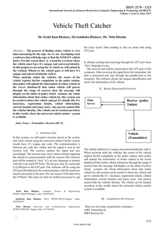
- 1. ISSN: 2278 – 1323 International Journal of Advanced Research in Computer Engineering & Technology (IJARCET) Volume 2, Issue 6, June 2013 2155 www.ijarcet.org Abstract— The process of finding stolen vehicle is very time-consuming for the cops. So, we are developing such a software that will help cops to find the STOLEN vehicle faster. For this reason there is a need for a system where the vehicle must have it’s unique and universal identity. In this project we are using the Ic which we will embed in the vechicle. Whenever the vehicle goes, it will have it’s unique and universal identity with it. When anybody stolen the vehicles, the owner of the vehicle register his/her complaints to the police station, then police will upload the information of stolen vehicle in the server database.If that stolen vehicle will passes through the range of receiver then the message will display on the tablet of police which contains the whole information about that stolen vehicle.So, this system can be useful to detect the vehicle and get it’s details like it’s insurance, registration details, vehicle information, current location and many more. Any person cannot hide the vehicles identity. The vehicle can be tracked anywhere in this world, where the universal vehicle catcher system is available. Index Terms—Transmitter, Receiver,RF IC, I. INTRODUCTION In this system, we will need a receiver circuit at the system end. Each vehicle using the universal vehicle Catcher system would have it‘s unique pin code. The communication is between pin with the vehicle and the signal is sent to the receiver end. The receiver catches the signal and acts accordingly. The receiver may show various details regarding the vehicle in communication with the receiver.The software part will be created in ‗Java‘. It‘s an easy language to interact with the Com and LPT Ports. The devices may be connected to COM port or the LPT port. Our software will be using the LPTport (Parallel port) for communication with the hardware circuit connected to the port. We can receive 8-bit data from the LPTport. This data can then be further processed to get Ketki Ram Bhakare, Computer Science & Engineering, RTMNU/DBACERNagpur, India, 9860582654 Samiksha Ram Bhakare, MCA, RTMNU/BCCE.Nagpur, India, 9209206202 Nitin Bhomle, Electronic and Communication Engineering, RTMNU/DBACER .Nagpur India, 8412963663 ). the exact result. Data sending is also an easier task using LPT port. In all data sending and receiving through the LPT port from ‗Java‘ language is easy. The receiver end will be connected to the LPT port of the computer. After receiving the signal from the transmitter, the data is processed and sent through the parallel port to the computer. The software checks the unique identification and shows the information of the vehicle. II. BLOCK DIAGRAM OF SYSTEM The vehicle will have it‘s unique and universal identity with it. When anybody stole the vehicles, the owner of the vehicle register his/her complaints to the police station, then police will upload the information of stolen vehicle in the server database.If that stolen vehicle will passes through the range of receiver then the message will display on the tablet of police which contains the whole information about that stolen vehicle.So, this system can be useful to detect the vehicle and get it‘s details like it‘s insurance, registration details, vehicle information, current location and many more. Any person cannot hide the vehicles identity. The vehicle can be tracked anywhere in this world, where the universal vehicle catcher system is available. III. COMPONENT OF SYSTEM There are two main components of project:- A)RF Transmiter IC. B)RF Reciever IC. Vehicle Theft Catcher Ms. Ketki Ram Bhakare, Ms.Samiksha Bhakare, Mr. Nitin Bhomle Main Server Reciver (police Tablet) Vehicle (Transmitter)
- 2. ISSN: 2278 – 1323 International Journal of Advanced Research in Computer Engineering & Technology (IJARCET) Volume 2, Issue 6, June 2013 www.ijarcet.org 2156 A. RF Transmiter IC. 0 VCC 0 0 R3 R5 R4 C1 C2 R6 R7 R8 31Ohm ANTENNA 1 T3 T1 ICTx2 40927287 1 2 3 4 5 7 10 6 14 13 12 11 8 9 T T T T T SO T T T T T T T T C6 R1 T2 R2 R9 C4 C3 C5 SW1 SW2 SW3 SW4 R10 104 pF 220 Ohm 440K 440K 440K 440K 108 pF 2.2 K 104 pF 104 pF 104 pF 104 pF 100 Ohm 100 Ohm 100 Ohm 35,468 MHz S9018 S9018 S9018 RF TRANSMITTER CIRCUIT In this type of transmitter circuit IC used is TX 2 40927287. It is also called as tone generator IC. It is a 14pin IC. In this IC Pin no. 1 is connected to switch 1 through ground (i.e. switch is pressed, ground is connected to pin no. 1). Similarly, pin no. 3 connected to switch 2 through a ground, pin no 4 is connected to switch 3 through ground .And pins 7 and 6 connected to switch 4 through a ground. When the particular switched is pressed the IC will generate particular tone signal Pin no. 9 is connected to 3V Vcc through battery. Pin no 14 is also connected to ground or negative terminal of battery. Pin no. 8 is output pin. Pin no 11 and 14 are short through resistor 31 ohms. B. RF Receiver IC. In this type of receiver circuit, antenna receives particular frequency. Inductor L1 and capacitor C1 and C2 and resistor 22 ohms are used to filter the signal (noise signal) It is also called Inductor capacitor filter. The other circuit uses the transistor T1 and capacitor C3, C4, R7, C9, C7, R6, C5, C6, diode D1, R8, C11, C1 and C5. It is used to filter and amplify the frequency given to pin no. 13 of Rx-2 503113287 I. The pin 1,2,3 are connected to the capacitor C12, R19, and R7. Pin 4 and 5 are connected to resistor R10. Pin 6,7,12 and 11 are output pins. The IC is used to receive the particular frequency and the particular pin of IC (output pin 6,7,12,11) is active or high logic. The base of transistor T2, T5, T8, T11 is active and collector voltage flows through the ammeter through the LED‘s, then the LED‘s will glow. b)RF <Doc> <RevCode> <Title> A 1 1Thursday, February23, 2006 Title Size Document Number Rev Date: Sheet of 9vdc 9V 9V 9V 9V 9V 9V 9V9V 104 pF <> 22 uF 108 pF C522 uF U1 1 2 3 4 5 6 7 8 16 15 14 13 12 11 10 9 104 pF L1 108 pF 470 uF 104 pF 4.7uF 104 pF R1 ANTENNA 1 D1 ZM4730A/CYL s9014 T1 LED+ LED-- LED+ LED-- LED+ LED-- LED+ LED-- 22 M 210 k 22 Ohm 550 Ohm 200 K 2.2 K 2.2 K 2.2 K 100 Ohm 1K 1K 22 M 10 K 550 Ohm B- 20 Ohm RX-2 50311287 S9014 T2 S9014 T3 108 pF R7 R4 R2 R8 R6 R7 R9 R10 R11 R14 R13 R12 R5 R3 C1 C2 C3 C4 C5 C6 C7 C8 C9 C10 C11 C12 RF RECEIVER CIRCUIT 100 Ohm S9014 T5 S9014 T6 S9014 T4 R15 S9014 T8 R16 S9014 T7 S9014 T9 100 Ohm S9014 T12 S9014 T11 R17 100 Ohm S9014 T13 S9014 T10 IV. MODULES There are three main modules of project:- A .Authentication Screen and Flash Screen Module B. .Main Screen Module C. .Hardware interfacing Module A. .Authentication Screen and Flash Screen Module: Check authentication user and their password.If they will match then next screen will appear. Otherwise, message box show for invalid username and password. It will display 10-20 sec and it‘s content will stud_name, col_name,guide_name etc.Then 10-20 sec main screen will appear. Username & Password : Here Admin will enter the username and password. If it is valid then main screen module will get open.
- 3. ISSN: 2278 – 1323 International Journal of Advanced Research in Computer Engineering & Technology (IJARCET) Volume 2, Issue 6, June 2013 2157 www.ijarcet.org Fig 1. Showing Admin Login Screen B. Main Screen Module: It will display various menu‘s like: 1. Registration 2. Detection 1. In Registration Menu there are three Submenu a)Vehicle registration entry: This module is used for registering new vehicle entries. b)Complaint registration: This module is used to register complaints of stolen vehicle. c) Exit: This module is used to exit from the main menu. Fig 2. Showing Main Screen Module a)Vehicle registration entry module When we click on the vehicle registration menu, then it will display registration form.In this form will appear various textbox,buttons(Add,Remove,Modify,Personal information of customer as well as vehicle). In Add form we will feed all the information about the vehicle i.e. name of vehicle,its UID,licence no.etc. In Modify form we will update respective(that we want to modify) information about vehicle. After Clicking on Registration submenu, vehicle entry form will get open. After clicking on add new button on form, we will add new vehicle information . Fig 3. Showing Vehicle registration entry Form. b)Complaint Form: This module is used to register complaints of stolen vehicle. We can modify this data also. In this form we will also see the previous and next complaint registered Fig 4. Showing Complaint registration form 2. In Detection Menu there are again three submenu- a) Complaint Detection Form b) Insurance Lapse Detect Form: c) Traffic rule break a)Complaint Detection Form: When we click on the complaint detection submenu then it will display the complaint detection form. The transmitter chip in vehicle continuously transmit the signals (with signal vehicle transmit its unique UID) and receiver IC in police tablet continuously receive the signal. When any stolen vehicle whose complaint is registered is passes nearby
- 4. ISSN: 2278 – 1323 International Journal of Advanced Research in Computer Engineering & Technology (IJARCET) Volume 2, Issue 6, June 2013 www.ijarcet.org 2158 from police tablet. Police tablet receive the signal along with the UID of vehicle , police tablet passes this UID to the server, then server will check whether the vehicle with this UID is a stolen vehicle or not. If it is then server reply this to the police tablet. In police tablet complaint detection window get pop up. It will display all the information of stolen Vehicle. In this way police can caught the theft who stole the vehicle. Fig 5. Showing Complaint Detect form b) Insurance Lapse Detect Form: The same process in complaint detection form(stolen vehicle detection) is followed in this case. But only change is that if the vehicle with insurance lapse will pass from police tablet, then Insurance Lapse Detect Form will get open. Fig 6. Insurance Lapse Detect Form C. Hardware interfacing Module: 1)Hardware interfacing with LPT port programming. PC parallel port is 25 pin D-shaped female connector in the back of the computer. It is normally used for connecting computer to printer, but many other types of hardware for that port is available today. 2)Reciever circuit and Transmitter circuit. Receiver IC is connected to LPT port of PC it receives the Signals from transmitter IC. Transmitter IC is embedded in vehicle and it is used to transmit the signal. 3)Ic Name:IM-283. The IM283 is a fully-integrated 125 kHz RFID reader Circuit .IM283 is versatile enough to work in most low-power (short distance) and high power (longer distance) applications. CONCLUSION In this way we are able to find the stolen vehicles in shorter period of time and also it reduces the overhead of cops to find the stolen vehicle. REFERENCES [1] J. Pourrostam,S. A. Zekavat, and H. Tong ―Novel Direction-of-Arrival Estimation Techniques for PeriodicSense Local Positioning Systems in Wireless Environment,‖ proceedings IEEE Radar’07, 17 – 20 April, 2007, Boston. [2] H. Tong and S. A. Zekavat, ―A Novel Wireless Local Positioning System via Asynchronous DSCDMA and Beam-forming: Implementation and Perturbation Analysis,‖ IEEE Trans. On Vehicular Technology, vol. 56, no. 3, pp. 1307 – 1320, May 2007. [3] S. A. Zekavat, H. Tong, and J. Tan, "A novel wireless local positioning system for airport(indoor) security, " Proceedings SPIE Conference on Defense and Security 2004, Orlando, FL,pp. 522-533, April 2004. [4] ―A Low-Power RF Direct-Conversion Receiver/Transmitter for 2.4 GHz-band IEEE 802.15.4 Standard in 0.18-µm CMOS Technology, ―IEEE Trans On Microwave Theory and Technique, vol Volume:54 , Issue: 12 , pp. 4062 – 4071,Dec 2006. [5] Wikipedia, ―Wireless sensor network — wikipedia, the free encyclopedia,‖ 2008 [6] Wikipedia, ―RF-Module — wikipedia, the free encyclopedia,‖ 2011. Ketki RamBhakare , have done BE fromKDKCE,Nagpur and Have done MTech(cse) from RCERT,Chandrapur. Working as a lecturer in DBACER,Nagpur. Samiksha RamBhakare, have done BSc(Computer Science) from Kamla Nehru College,Nagpur and have done MCA from Priyadarshani College of Engineering Nagpur.Working as a lecturer in BCCE,Nagpur. Nitin Bholme, have done BE from YCCE,Nagpur and Have done MTech(cse) from NIT Trichy. Working as a lecturer in DBACER,Nagpur.