Finite Element Analysis of Skirt to Dished junction in a Pressure Vessel

International Journal of Modern Engineering Research (IJMER) is Peer reviewed, online Journal. It serves as an international archival forum of scholarly research related to engineering and science education. International Journal of Modern Engineering Research (IJMER) covers all the fields of engineering and science: Electrical Engineering, Mechanical Engineering, Civil Engineering, Chemical Engineering, Computer Engineering, Agricultural Engineering, Aerospace Engineering, Thermodynamics, Structural Engineering, Control Engineering, Robotics, Mechatronics, Fluid Mechanics, Nanotechnology, Simulators, Web-based Learning, Remote Laboratories, Engineering Design Methods, Education Research, Students' Satisfaction and Motivation, Global Projects, and Assessment…. And many more.

Recomendados
Recomendados
Mais conteúdo relacionado
Mais procurados
Mais procurados (19)
Destaque
Destaque (20)
Semelhante a Finite Element Analysis of Skirt to Dished junction in a Pressure Vessel
Semelhante a Finite Element Analysis of Skirt to Dished junction in a Pressure Vessel (20)
Mais de IJMER
Mais de IJMER (20)
Último
Último (20)
Finite Element Analysis of Skirt to Dished junction in a Pressure Vessel
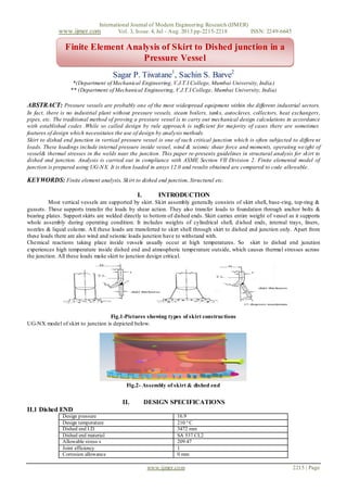
- 1. International Journal of Modern Engineering Research (IJMER) www.ijmer.com Vol. 3, Issue. 4, Jul - Aug. 2013 pp-2215-2218 ISSN: 2249-6645 www.ijmer.com 2215 | Page Sagar P. Tiwatane1 , Sachin S. Barve2 *(Department of Mechanical Engineering, V.J.T.I College, Mumbai University, India) ** (Department of Mechanical Engineering, V.J.T.I College, Mumbai University, India) ABSTRACT: Pressure vessels are probably one of the most widespread equipment within the different industrial sectors. In fact, there is no industrial plant without pressure vessels, steam boilers, tanks, autoclaves, collectors, heat exchangers, pipes, etc. The traditional method of proving a pressure vessel is to carry out mechanical design calculations in accordance with established codes .While so called design by rule approach is sufficient for majority of cases there are sometimes features of design which necessitates the use of design by analysis methods. Skirt to dished end junction in vertical pressure vessel is one of such critical junction which is often subjected to differe nt loads. These loadings include internal pressure inside vessel, wind & seismic shear force and moments, operating weight of vessel& thermal stresses in the welds near the junction. This paper re-presents guidelines in structural analysis for skirt to dished end junction. Analysis is carried out in compliance with ASME Section VII Division 2. Finite elemental model of junction is prepared using UG-NX. It is then loaded in ansys 12.0 and results obtained are compared to code allowable. KEYWORDS: Finite element analysis, Skirt to dished end junction, Structural etc. I. INTRODUCTION Most vertical vessels are supported by skirt. Skirt assembly generally consists of skirt shell, base-ring, top-ring & gussets. These supports transfer the loads by shear action. They also transfer loads to foundation through anchor bolts & bearing plates. Support skirts are welded directly to bottom of dished ends. Skirt carries entire weight of vessel as it supports whole assembly during operating condition. It includes weights of cylindrical shell, dished ends, internal trays, liners, nozzles & liquid column. All these loads are transferred to skirt shell through skirt to dished end junction only. Apart from these loads there are also wind and seismic loads junction have to withstand with. Chemical reactions taking place inside vessels usually occur at high temperatures. So skirt to dished end junction experiences high temperature inside dished end and atmospheric temperature outside, which causes thermal stresses across the junction. All these loads make skirt to junction design critical. Fig.1-Pictures showing types of skirt constructions UG-NX model of skirt to junction is depicted below. Fig.2- Assembly of skirt & dished end II. DESIGN SPECIFICATIONS II.1 Dished END Design pressure 16.9 Design temperature 210 º C Dished end I.D 3472 mm Dished end material SA 537 CL2 Allowable stress s 209.47 Joint efficiency 1 Corrosion allowance 0 mm Finite Element Analysis of Skirt to Dished junction in a Pressure Vessel
- 2. International Journal of Modern Engineering Research (IJMER) www.ijmer.com Vol. 3, Issue. 4, Jul - Aug. 2013 pp-2215-2218 ISSN: 2249-6645 www.ijmer.com 2216 | Page Fig 3- Bottom hemispherical dished end Minimum Required Thickness as ASME SEC. VIII DIV 2 Part 4, = + = + = 71.8173 + 0.000 + 0.000 = 71.8173 mm Finished thickness = 78 mm 2.2 Skirt specifications: Skirt material SA 516 GR.70 Skirt thickness 45 mm Corrosion allowance 0 mm III. ANALYSIS DETAILS The 180 º sector 3D finite element model for head to skirt junction was prepared in Uni-graphics (UG). In order to reduce the overall size of FE model only half portion of the skirt to dished end assembly was considered. Meshing of model is carried out by using UG. This FEA analysis is carried out in order to know the stress distribution near head to skirt junction due to internal pressure, discontinuities, operating weight and seismic loads. ANSYS 11.0 was used for pre- processing, solution and post-processing of this finite element analysis. Stress classification lines were plotted to know distribution of stresses at critical junction. Finally, resulting von-misses stresses were compared to code allowable. Component Skirt to dished head junction Software ANSYS 12.0 Analysis type Structural linear static Element Solid 45 III.1 Design data Design code ASME SEC VIII Div. 2 Design pressure 16.982 Mpa Design temperature 210 º C III.2 Material data Component Material Design temperature Allowable stress S skirt SA516GR70 210 ºC 138 MPa Bottomdished end SA 537CL2 210 ºC 134 MPa Allowable stresses for skirt & dished end material are obtained from table 5A,of ASME SEC. VIII Div.2,Ed2010 III.3 Meshed model: Fig 4- finite elemental model of skirt to dishedjunction
- 3. International Journal of Modern Engineering Research (IJMER) www.ijmer.com Vol. 3, Issue. 4, Jul - Aug. 2013 pp-2215-2218 ISSN: 2249-6645 www.ijmer.com 2217 | Page Stress classification lines (SCL) were plotted near junction and intensity of von misses stresses is observed across these junctions. Fig 5- location of stress classification lines in the junction IV. STRUCTURAL BOUNDARY CONDITIONS 1. Internal pressure has been applied on inside surface of dished end. P = 16.98 MPa 2. Operating weight of vessel including liquid and internals have been applied through center of gravity of vessel with the help of rigid elements. 3. W= 4208861 N 4. Horizontal Seismic shear force = 2212515 N 5. Seismic base moment = 28 .827 × N-mm 6. Seismic moment acting at C.G 7. = Seismic base moment – Seismic shear force distance from base model to top 8. = – 2212515 × 11870 = N-mm 9. Axial thrust on dished end thickness 10. Longitudinal stress due to internal pressure = = = 107.36 MPa Stress due to operating weight = a. = 2.7962 MP 11. So, resulting axial thrust on dished end thickness = 107.36 – 2.7962 = 104.5638 MPa 12. Base of the skirt is constrained in all directions. IV.1 Loads and boundary conditions: Fig 6- Boundary conditions V. RESULTS & DISCUSSIONS Model is solved for above mentioned loadings in ansys 12.0 deformation plot and von misses stress plot are obtained. Maximum primary stress, bending stress across stress classification lines in the junction are summarized in the table. Fig 7- figure showing deformation in the junction
- 4. International Journal of Modern Engineering Research (IJMER) www.ijmer.com Vol. 3, Issue. 4, Jul - Aug. 2013 pp-2215-2218 ISSN: 2249-6645 www.ijmer.com 2218 | Page Fig 8 - Von misses stress plot Fig 9-Von misses stress plot acros stress classificatio lines (SCL) V.1 RESULTS TABLE Stress Classification Line (SCL) (2) Type of stress Max Induced Von Misses stress (MPa) Allowable Design stress (MPa) (1) SCL 1: In Shell at Shell to Skirt Joint Pl 154.4 1.5 S = 201 Pl + Pb + Q 50.81 3 S = 402 SCL 2 : In Dish End at Shell to Skirt Joint Pl 168.4 1.5 S = 201 Pl + Pb + Q 74.04 3 S = 402 SCL 3: In Skirt at Shell to Skirt Joint Pl 94.65 1.5 S = 207 Pl + Pb + Q 36.06 3 S = 414 Primary & secondary stresses induced in the junction across stress classification lines are compared to code allowable & are found within allowable limit which justifies structural stability of the junction. VI. CONCLUSION a. This analysis throws light on various stresses encountered in the skirt to dished junction which makes its design critical. b. After this analysis optimumparameters should be considered which can minimize stresses in junction. This can increase life of pressure vessel & reduce its cost. c. It can be concluded that stress and other parameters are also decreased by changing weld size of skirt to dished end junction. VII. ACKNOLEDGEMENT Authors are grateful to M/S Larsen and Toubro Ltd, powai for allowing themto carry out the project work during the course of study. We are indebted to design department and the staff for their help. REFERANCES Books [1]. ASME code, Section VIII, Division 2, 2010 A-11 [2]. Moss D. R. Pressure Vessel Design Manual Third edition.