
Recomendados
Mais conteúdo relacionado
Mais procurados
Mais procurados (20)
Semelhante a Hospital Management system Database design
Semelhante a Hospital Management system Database design (20)
Mais de Elias Dinsa
Hospital Management system Database design
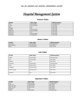
- 1. THE ER DIAGRAM FOR HOSPITAL MANAGEMENT SYSTEM Hospital Management System Patient Table: Fields Data Type Relationships Pid Varchar(5) Primary Key name Varchar(20) Not Null age int Not Null weight int Not Null gender Varchar(10) Not null address Varchar(50) Not Null phoneno int Not Null disease Varchar(20) Not Null doctorid Varchar(5) Not Null Doctor Table: Fields Data Type Relationships doctorid Varchar(5) Primary Key doctorname Varchar(15) Not Null dept Varchar(15) Not Null Lab Table: Fields Data Type Relationships labno Varchar(5) Primary Key pid Varchar(5) Not Null weight int Not Null doctorid Varchar(5) Foreign Key date Date/Time Not Null category Varchar(15) Not Null patient_type Varchar(15) Not Null amount int Not Null Inpatient Table: Fields Data Type Relationships pid Varchar(5) Primary Key room_no Varchar(50) Not Null date_of_adm Date/Time Not Null date_of_dis Date/Time Not Null advance int Not Null labno Varchar(5) Foreign Key
- 2. THE ER DIAGRAM FOR HOSPITAL MANAGEMENT SYSTEM Outpatient Table: Fields Data Type Relationships pid Varchar(5) Primary Key date Date/Time Not Null labno Varchar(5) Foreign Key Room Table: Fields Data Type Relationships room_no Varchar(50) Primary Key room_type Varchar(10) Not Null status Varchar(10) Not Null Bill Table: Fields Data Type Relationships bill_no Varchar(50) Primary Key pid Varchar(5) Foreign Key patient_type Varchar(10) Allow Null doctor_charge int Not Null medicine_charge int Not Null room_charge int Not Null oprtn_charge int Allow Null no_of_days int Allow Null nursing_charge int Allow Null advance int Allow Null health_card Varchar(50) Allow Null lab_charge int Allow Null bill int Not Null E-R Diagram Entity relationship diagram is used in modern database software engineering to illustrate logical structure of database. It is a relational schema database modeling method used to model a system and approach. This approach commonly used in database design. The diagram created using this method is called E-R diagram. Hospital Management System The E-R diagram depicts the various relationships among entities considering each object as entity. Entity is represented as diamond shape and relationship is represented as rectangle. It depicts the relationship between data objects. The E-R diagram is the relation that is used to conduct the data modeling activity.
- 3. THE ER DIAGRAM FOR HOSPITAL MANAGEMENT SYSTEM Entity:- Entity is the thing which we want to store information. It is an elementary basic building block of storing information about business process. An entity represents an objects defined within the information system about which you want to store information. Relationship:- A relationshipis named connection or association between entities used to relate two or more entities with some common attributes of meaningful interaction between the object. Attributes:- Attributes are the properties of the entities and relationship. Descriptor of the entity. Attributes are elementary pieces of and information attached to an entity. Symbols Their Respective Meaning Symbols Meaning Entity Relationship Attribute Key Attribute Cardinality Ratio N: 1 for E1: E2 in R E1 R E2
- 4. THE ER DIAGRAM FOR HOSPITAL MANAGEMENT SYSTEM patient weight doctorid gender address phone no Consults doctor Doctorid Doctor name dept Checks labReport labno Pid weight doctorid date category Decides inpatient outpatient labno room no pid advance date of admission date of discharge pid labno date Admitted to to room status room no room type issued_to bill bill no pid labcharge patienttype bill doctor chargeadvance health card medicine charge room charge operation charge no of days nursing charge disease amount pid name age