Lintech 130series specsheet
•
0 gostou•183 visualizações

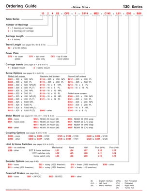
The document provides specifications for a 130 series screw drive table, including: - Details on the number of bearings, carriage length, travel length, cover plates, screw and motor options. - Dimensions for the table base, carriage, end plates and various mounting options. - Load capacity, thrust force capacity, acceleration limits and other performance specifications. - Contact information for the manufacturer, Electromate, is provided at the end.

Recomendados
Mais conteúdo relacionado
Mais procurados
Mais procurados (16)
Destaque
Destaque (15)
Semelhante a Lintech 130series specsheet
Semelhante a Lintech 130series specsheet (16)
Mais de Electromate
Mais de Electromate (20)
Último
Último (20)
Lintech 130series specsheet
- 1. Ordering Guide - Screw Drive - 130 Series Table Series Number of Bearings 1 - 1 bearing per carriage 2 - 2 bearings per carriage Carriage Length 4 - 4 inches 13 2 4 02 - CP0 - 1 - - M02 - C145 - L01 - E00 - B00 Travel Length (see pages B-6, B-8 & B-10) 02 - 2 to 60 inches Cover Plate CP0 - no cover plates Screw Options (see pages B-14 to B-19) Rolled ball screws S001 - S002 - .500 x .500 NPL .500 x .500 PL S003 - .500 x .500 NPL(T) S005 - .625 x .200 NPL S006 - S009 - S010 - .625 x .200 PL .625 x 1.000 NPL .625 x 1.000 PL other Precision ball screws - .625 x .200 NPL - - - - - S114 S115 S116 S117 S118 S119 S120 S121 S999 - other M03 - NEMA 23 mount (M) Coupling Options (see pages B-38 to B-39) C000 - none .625 x .200 PL 16 x 5 NPL 16 x 5 PL 16 x 10 NPL 16 x 10 PL C020 to C024 - C100 C040 to C047 - C125 Limit & Home Switches (see pages B-35 to B-37) EOT & home switches Encoder Options (see page B-45) E00 - none E01 - rotary (500 lines/rev) Power-off Brakes (see page B-44) Specifications subject to change without notice Ground ball screws S213 - .625 x .500 PL Rolled acme screws S301 - M06 - NEMA 23 (RH) wrap M08 - NEMA 34 (RH) wrap C125 to C129 - H100 C145 to C154 - H131 E02 - rotary (1000 lines/rev) E03 - rotary (1270 lines/rev) Prox (NPN) Prox (PNP) E10 - linear (2500 lines/inch) E99 - other B00 - none B01 - 24 VDC B02 - 90 VDC B99 - other C400 to C406 - G100 C999 - other C425 to C434 - G126 EOT switches only L00 - no switches home switch only Mechanical Reed Hall L01 L02 L03 L04 L05 L06 L07 L08 L09 L10 L11 L12 L99 - other E11 - linear (125 lines/mm) Carriage Inserts (see pages B-7, B-9 & B-11) 1 - English mount 2 - Metric mount S007 - .625 x .200 NPL(T) S011 - .625 x 1.000 NPL(T) - .625 x .200 PL - - 16 x 5 PL 16 x 16 PL .625 x .100 NPL .625 x .100 PL .625 x .200 NPL .625 x .200 PL - - 16 x 16 NPL 16 x 16 PL Motor Mount (see pages B-7, B-9, B-11, B-42 & B-43) M00 - none M01 - hand crank M02 - NEMA 23 mount (E) M04 - NEMA 34 mount (E) M07 - M09 - NEMA 23 (LH) wrap M99 - M05 - NEMA 34 mount (M) NEMA 34 (LH) wrap S212 S214 S215 - - - S300 S302 S303 16 x 4 NPL 16 x 4 PL - - S304 S305 S114 L13 L14 L15 (E) - English Interface (LH) - Left Hand (M) - Metric Interface (NPL) - Non Preloaded (PL) - Preloaded (RH) - Right Hand (T) - Turcite Nut CP1 - top cover plate only CP2 - top & side cover plates S004 - .500 x .500 PL(T) S008 - .625 x .200 PL(T) S012 - .625 x 1.000 PL(T)
- 2. Technical Reference - Screw Drive - 130 Series Load Capacities One (1) Bearing Carriage Two (2) Bearing Carriage 200 lbs 68 lbs 400 lbs 16 ft-lbs 5 ft-lbs 28 ft-lbs 15 ft-lbs 5 ft-lbs 30 ft-lbs 100 lbs 200 lbs 665 lbs ( 4 Thrust Force Capacity 500 million screw revolutions 180 lbs ( 82 kg) 180 lbs ( 82 kg) 150 in/sec2 ( 90 kg) ( 30 kg) (180 kg) ( 22 N-m) ( 7 N-m) ( 38 N-m) ( 20 N-m) ( 7 N-m) ( 40 N-m) ( 45 kg) ( 90 kg) (302 kg) (3,8 m/sec2) Table Material Base, Carriage, End Plates, & Cover Plate option - 6061 anodized aluminum Linear Rail Material microns/25mm) microns/25mm) Specifications subject to change without notice Dynamic Horizontal 2 million inches (50 km) of travel 100 lbs ( 45 kg) Dynamic Horizontal 50 million inches (1270 km) of travel 34 lbs ( 15 kg) Static Horizontal 200 lbs ( 90 kg) Dynamic Roll Moment 2 million inches (50 km) of travel 8 ft-lbs ( 11 N-m) Dynamic Roll Moment 50 million inches (1270 km) of travel 3 ft-lbs N-m) Static Roll Moment 14 ft-lbs ( 19 N-m) Dyn. Pitch & Yaw Moment 2 million inches (50 km) of travel 4 ft-lbs ( 5,4 N-m) Dyn. Pitch & Yaw Moment 50 million inches (1270 km) of travel Static Pitch & Yaw Moment 8 ft-lbs ( 10 N-m) 1 ft-lbs ( 1,9 N-m) Each Bearing Dyn. Capacity 2 m illion inches (50 km) of travel 100 lbs ( 45 kg) Each Bearing Static Load Capacity 200 lbs ( 90 kg) Thrust Force Capacity 10 million screw revolutions 665 lbs (302 kg) Maximum Acceleration 50 in/sec2 d - 2 Center to center distance (spacing) of each bearing on a single rail dr Center distance of the bearing to top of carriage plate surface dr (1,3 m/sec2) CP0 version CP1 version Center distance of the bearing to top of carriage plate surface 0.750 in (19,1 mm) 1.375 in (34,9 mm) 2.088 in (53,0 mm) 0.750 in (19,1 mm) 1.375 in (34,9 mm) Specifications Each Bearing Dyn. Capacity 5 0 million inches (1270 km) of travel 34 lbs ( 15 kg) 34 lbs ( 15 kg) For One (1) & Two (2) Bearing Carriages Screw Material (see pages B-14 to B-19) Stainless Steel Acme Screw - Stainless Steel Rolled Ball, Precision Ball, & Ground Ball - Case Hardened Steel Other Screw Material (see pages B-14 to B-19) Straightness < 0.00013 in/in Flatness < 0.00013 in/in (< (< 3,30 3,30 Orthogonality (multi-axis systems) < 30 arc-seconds Friction Coefficient < 0.01 Motor Mount NEMA 23 & 34 Mounts, Metric Mounts, Motor Wraps, and Hand Crank Option Coupling Three (3) different styles available Sold & Serviced By: ELECTROMATE Toll Free Phone (877) SERVO98 Toll Free Fax (877) SERV099 www.electromate.com sales@electromate.com
- 3. Technical Reference - Screw Drive - 130-CP0 Series - Without Cover Plates - Mounting Dimensions inches (mm) Dimensions & Specifications Table Dimensions inches (mm) Travel Length Screw Length inches (mm) 9.25 (235) Table Weight Model Number lbs (kg) C 4.8 inches (mm) A 6.0 (152,4) B 9.875 (250,8) 0.188 (4,8) E M 13x402-CP0 3 8 (2,2) 11.875 (301,6) 1.188 (30,2) 8 11.25 13.875 (352,4) 0.313 (8,0) 12 13.25 15.875 (403,2) 1.313 (33,4) 12 15.25 19.875 (504,8) 1.438 (36,5) 16 19.25 23.875 (606,4) 1.563 (39,7) 20 23.25 27.875 (708,0) 1.688 (42,9) 24 27.25 31.875 (809,6) 1.813 (46,1) 28 31.25 37.875 (962,0) 1.063 (27,0) 36 37.25 43.875 (1114,4) 0.313 (8,0) 44 43.25 49.875 (1266,8) 1.438 (36,5) 48 49.25 55.875 (1419,2) 0.688 (17,5) 56 55.25 61.875 (1571,6) 1.813 (46,1) 60 61.25 67.875 (1724,0) 1.063 (27,0) 68 67.25 x = 1; Carriage has 1 bearing; Carriage weight = 1.1 lbs. (0,50 kg) x = 2; Carriage has 2 bearings; Carriage weight = 1.2 lbs. (0,55 kg) (1) Footnotes: (1) Weight shown is with a 0.625 inch (16 mm) diameter screw, a 1 bearing carriage [1.1 lbs (0,55 kg)], a NEMA 23 motor mount [0.34 lbs (0,16 kg)], and a C100 style [0.09 lbs (0,04 kg)] coupling. When using a 0.500 inch diameter screw subtract 0.022 lbs per inch (0,00039 kg per mm) of screw length for a given model number. When using a 2 bearing carriage add 0.1 lbs (0,05 kg) to each value. Sold & Serviced By: Specifications subject to change without notice 5.3 13x404-CP0 8.0 (203,2) 3 (286) (2,4) 2 (50) 4 (100) 5.8 13x406-CP0 6 10.0 (150) (254,0) 5 (337) (2,6) 6.3 13x408-CP0 8 12.0 (200) (304,8) 5 (387) (2,9) 7.3 13x412-CP0 12 16.0 (300) (406,4) 7 (489) (3,3) 8.3 13x416-CP0 16 20.0 (405) (508,0) 9 (591) (3,8) 9.3 13x420-CP0 20 24.0 (505) (609,6) 11 (692) (4,2) 10.3 13x424-CP0 24 28.0 (605) (711.2) 13 (794) (4,7) 11.8 13x430-CP0 30 34.0 (760) (863,6) 17 (946) (5,4) 13.3 13x436-CP0 36 40.0 (910) (1016,0) 21 (1099) (6,0) 14.8 13x442-CP0 42 46.0 (1060) (1168,4) 23 (1251) (6,7) 16.3 13x448-CP0 48 52.0 (1215) (1320,8) 27 (1403) (7,4) 17.8 13x454-CP0 54 58.0 (1370) (1473,2) 29 (1556) (8,1) 19.3 13x460-CP0 60 64.0 (1520) (1625,6) 33 (1708) (8,8) version: 01/2014 ELECTROMATE Toll Free Phone (877) SERVO98 Toll Free Fax (877) SERV099 www.electromate.com sales@electromate.com
- 4. Technical Reference - Screw Drive - 130-CP0 Series 4.000 (101,60) 2.188 (55,58) 2.088 (53,03) Dimensions C E # of spaces C (1) A B (2) .193 (4,90) Dia.Thru Holes inches (mm) .375 (9,53) (1) This value is center to center distance (spacing) of the bearings on a single rail (d2). (2) This value is center distance of the bearing to top of carriage plate surface (dr). Optional NEMA 23 Motor Mount Shown: (4) Holes on 2.625 (66,68) Bolt Circle Dia. English Mount (M02): #10-24 thd. Metric Mount (M03): M5 thd. 1.502 (38,15) Pilot Dia. TYP EOT & HOME Switch Cable Egress .193 (4,90) Dia.Thru Holes, M # of Holes C' Bored Opposite Side .312 (7,92) Dia. x .190 (4,83) Deep Sold & Serviced By: Specifications subject to change without notice 2.188 (55,58) .719 TYP (18,26) TYP 1.875 (47,63) 2.531 (64,29) 2.875 (73,03) .344 TYP (8,74) TYP .625 (15,88) .500 (12,70) .75 (19,05) 1.000 (25,40) 2.375 (60,33) .250 TYP (6,35) TYP .375 (9,53) 2.312 (58,73) .156 TYP (3,96) TYP 2.188 (55,58) 1.125 (28,58) 1.094 TYP (27,79) TYP .500 TYP (12,70) TYP 1.875 (47,63) 1.875 (47,63) 1.188 (30,18) - Without Cover Plates - 1.875 (47,63) 1.875 (47,63) 1.875 (47,63) o .375 (9,93) .750 (19,05) .312 (7,92) o .375 (9,53) 303 Woodruff Keyway 2.375 (60,33) For optional coupling info see pages B-38 & B-39. Note: Any 130 series table can be mounted on top of a second 130 series table, in order to create X-Y multiple axis configurations. LINTECH recommends that a 2 bearing carriage be used for the bottom axis, and that the top axis should never extend out more than 18 inches in either direction, from the bottom axis carriage edge, without the use of a support bearing system on the outer edges of the top axis. The 130-CP1, 130-CP2 or 140 series requires a Carriage Adapter Plate option. The carriage's threaded stainless steel insert hole pattern exactly matches the base mounting hole pattern on each table, therefore no adapter bracket or extra machining is required. However a precision square tool, or micrometer depth gauge, is required in order to obtain an orthogonality between the two tables of < 30 arc-seconds. The table base, carriage top & carriage sides are all precision machined. LINTECH's 100 or 120 series tables should be used for the bottom axis in a mutiple axes applica-tion for better system rigidity, performance, and life. Threaded Stainless Steel Inserts: English Inserts (-1): (8) #8-32 x .25 inch deep TYP Metric Inserts (-2): (8) M4 thd. x 8 mm deep TYP TWO bearing carriage shown. ONE bearing carriage will have bearing centered on the carriage. ELECTROMATE Toll Free Phone (877) SERVO98 Toll Free Fax (877) SERV099 www.electromate.com sales@electromate.com
- 5. Technical Reference - Screw Drive - 130-CP1 Series Dimensions & Specifications Travel Length Table Dimensions Model Number lbs (kg) inches (mm) C inches (mm) Mounting Dimensions 5.5 inches (mm) A 6.0 (152,4) B 9.875 (250,8) 0.188 (4,8) E M 13x402-CP1 8 (2,5) Screw Length inches (mm) 9.25 (235) Table Weight 13x404-CP1 (2,8) 8.0 13x406-CP1 (3,1) 10.0 13x408-CP1 (3,4) 12.0 13x412-CP1 (4,0) 16.0 13x416-CP1 (4,5) 20.0 13x420-CP1 (5,1) 24.0 13x424-CP1 (5,7) 28.0 13x430-CP1 (6,6) 34.0 13x436-CP1 (7,5) 40.0 13x442-CP1 (8,4) 46.0 13x448-CP1 (9,3) 52.0 13x454-CP1 (10,1) 58.0 13x460-CP1 (11,0) 64.0 x = 1; Carriage has 1 bearing; Carriage weight = 1.4 lbs. (0,64 kg) x = 2; Carriage has 2 bearings; Carriage weight = 1.5 lbs. (0,68 kg) (1) 3 6.2 (203,2) 11.875 (301,6) 1.188 3 8 11.25 (30,2) (286) 2 (50) 4 (100) 6.8 (254,0) 13.875 (352,4) 0.313 (8,0) 12 13.25 5 (337) 6 (150) 7.4 (304,8) 15.875 (403,2) 1.313 (33,4) 12 15.25 5 (387) 8 (200) 8.8 (406,4) 19.875 (504,8) 1.438 (36,5) 16 19.25 7 (489) 12 (300) 10.0 (508,0) 23.875 (606,4) 1.563 (39,7) 20 23.25 9 (591) 16 (405) 11.3 (609,6) 27.875 (708,0) 1.688 (42,9) 24 27.25 11 (692) 20 (505) 12.6 (711.2) 31.875 (809,6) 1.813 (46,1) 28 31.25 13 (794) 24 (605) 14.6 (863,6) 37.875 (962,0) 1.063 (27,0) 36 37.25 17 (946) 30 (760) 16.5 (1016,0) 43.875 (1114,4) 0.313 (8,0) 44 43.25 21 (1099) 36 (910) 18.4 (1168,4) 49.875 (1266,8) 1.438 (36,5) 48 49.25 23 (1251) 42 (1060) 20.4 (1320,8) 55.875 (1419,2) 0.688 (17,5) 56 55.25 27 (1403) 48 (1215) 22.3 (1473,2) 61.875 (1571,6) 1.813 (46,1) 60 61.25 29 (1556) 54 (1370) 24.3 (1625,6) 67.875 (1724,0) 1.063 (27,0) 68 67.25 33 (1708) 60 (1520) Sold & Serviced By: Specifications subject to change without notice - With Top Cover Plate Only - Footnotes: (1) Weight shown is with a 0.625 inch (16 mm) diameter screw, a 1 bearing carriage [1.1 lbs (0,55 kg)], a NEMA 23 motor mount [0.34 lbs (0,16 kg)], and a C100 style [0.09 lbs (0,04 kg)] coupling. When using a 0.500 inch diameter screw subtract 0.022 lbs per inch (0,00039 kg per mm) of screw length for a given model number. When using a 2 bearing carriage add 0.1 lbs (0,05 kg) to each value. ELECTROMATE Toll Free Phone (877) SERVO98 Toll Free Fax (877) SERV099 www.electromate.com sales@electromate.com
- 6. Technical Reference - Screw Drive - 130-CP1 Series Dimensions 1.502 (38,15) Pilot Dia. TYP Sold & Serviced By: Specifications subject to change without notice - With Top Cover Plate Only - EOT & HOME Switch Cable Egress 2.500 (63,50) .250 (6,35) 2.312 (58,73) (4) Holes on 2.625 (66,68) Bolt Circle Dia. English Mount (M02): #10-24 thd. Metric Mount (M03): M5 thd. 1.188 (30,18) inches (mm) Optional Carriage Adapter Plate (see page B-34) .187 TYP (4,76) TYP Optional NEMA 23 Motor Mount Shown: .030 (0,80) (1) .193 (4,90) Dia.Thru Holes 1.875 (47,63) 1.875 (47,63) 1.875 (47,63) 1.875 (47,63) 1.875 (47,63) .193 (4,90) Dia.Thru Holes, M # of Holes C' Bored Opposite Side .312 (7,92) Dia. x .190 (4,83) Deep .156 TYP (3,96) TYP 2.188 (55,58) 1.125 (28,58) (1) This value is center to center distance (spacing) of the bearings on a single rail (d2). Note: Any 130 series table can be mounted on top of a second 130 series table, in order to create X-Y multiple axis configurations. LINTECH recommends that a 2 bearing carriage be used for the bottom axis, and that the top axis should never extend out more than 18 inches in either direction, from the bottom axis carriage edge, without the use of a support bearing system on the outer edges of the top axis. The 130-CP1, 130-CP2 or 140 series requires a Carriage Adapter Plate option. The carriage's threaded stainless steel insert hole pattern exactly matches the base mounting hole pattern on each table, therefore no adapter bracket or extra machining is required. However a precision square tool, or micrometer depth gauge, is required in order to obtain an orthogonality between the two tables of < 30 arc-seconds. The table base, carriage top & carriage sides are all precision machined. LINTECH's 100 or 120 series tables should be used for the bottom axis in a mutiple axes applica-tion for better system rigidity, performance, and life. 4.000 (101,60) 3.500 (88,90) .250 TYP (6,35) TYP 2.531 (64,29) 2.875 (73,03) .344 TYP (8,74) TYP .375 (9,93) .750 (19,05) .312 (7,92) o .375 (9,53) 303 Woodruff Keyway For optional coupling info see pages B-38 & B-39. Threaded Stainless Steel Inserts: English Inserts (-1): (8) #8-32 x .25 inch deep TYP Metric Inserts (-2): (8) M4 thd. x 8 mm deep TYP TWO bearing carriage shown. ONE bearing carriage will have bearing centered on the carriage. 2.088 (53,03) .625 (15,88) .375 (9,53) o A B .500 (12,70) 1.000 (25,40) 2.375 (60,33) (2) 1.375 (34,93) 3.000 (76,20) .250 TYP (6,35) TYP C E # of spaces C (2) This value is center distance of the bearing to top of carriage plate surface (dr). ELECTROMATE Toll Free Phone (877) SERVO98 Toll Free Fax (877) SERV099 www.electromate.com sales@electromate.com
- 7. Technical Reference - Screw Drive - 130-CP2 Series Dimensions & Specifications Travel Length Table Dimensions Model Number lbs (kg) 5.7 (2,58) 6.4 (2,90) 7.0 (3,17) 7.6 (3,45) 9.1 (4,13) 10.4 (4,72) 11.7 (5,31) 13.1 (5,94) 15.1 (6,85) 17.1 (7,76) 19.1 (8,66) 21.2 (9,62) 23.2 (10,52) 25.3 (11,47) inches (mm) C inches (mm) Mounting Dimensions 13x402-CP2 inches (mm) A 6.0 (152,4) B 9.875 (250,8) 0.188 (4,8) E M 8 Screw Length inches (mm) 9.25 (235) Table Weight x = 1; Carriage has 1 bearing; Carriage weight = 1.4 lbs. (0,64 kg) x = 2; Carriage has 2 bearings; Carriage weight = 1.5 lbs. (0,68 kg) (1) 3 13x404-CP2 8.0 (203,2) 11.875 (301,6) 1.188 3 8 11.25 (30,2) (286) 2 (50) 4 (100) 13x406-CP2 10.0 (254,0) 13.875 (352,4) 0.313 (8,0) 12 13.25 5 (337) 6 (150) 13x408-CP2 12.0 (304,8) 15.875 (403,2) 1.313 (33,4) 12 15.25 5 (387) 8 (200) 13x412-CP2 16.0 (406,4) 19.875 (504,8) 1.438 (36,5) 16 19.25 7 (489) 12 (300) 13x416-CP2 20.0 (508,0) 23.875 (606,4) 1.563 (39,7) 20 23.25 9 (591) 16 (405) 13x420-CP2 24.0 (609,6) 27.875 (708,0) 1.688 (42,9) 24 27.25 11 (692) 20 (505) 13x424-CP2 28.0 (711.2) 31.875 (809,6) 1.813 (46,1) 28 31.25 13 (794) 24 (605) 13x430-CP2 34.0 (863,6) 37.875 (962,0) 1.063 (27,0) 36 37.25 17 (946) 30 (760) 13x436-CP2 40.0 (1016,0) 43.875 (1114,4) 0.313 (8,0) 44 43.25 21 (1099) 36 (910) 13x442-CP2 46.0 (1168,4) 49.875 (1266,8) 1.438 (36,5) 48 49.25 23 (1251) 42 (1060) 13x448-CP2 52.0 (1320,8) 55.875 (1419,2) 0.688 (17,5) 56 55.25 27 (1403) 48 (1215) 13x454-CP2 58.0 (1473,2) 61.875 (1571,6) 1.813 (46,1) 60 61.25 29 (1556) 54 (1370) 13x460-CP2 64.0 (1625,6) 67.875 (1724,0) 1.063 (27,0) 68 67.25 33 (1708) 60 (1520) Sold & Serviced By: Specifications subject to change without notice - With Top & Side Cover Plates - Footnotes: (1) Weight shown is with a 0.625 inch (16 mm) diameter screw, a 1 bearing carriage [1.1 lbs (0,55 kg)], a NEMA 23 motor mount [0.34 lbs (0,16 kg)], and a C100 style [0.09 lbs (0,04 kg)] coupling. When using a 0.500 inch diameter screw subtract 0.022 lbs per inch (0,00039 kg per mm) of screw length for a given model number. When using a 2 bearing carriage add 0.1 lbs (0,05 kg) to each value. ELECTROMATE Toll Free Phone (877) SERVO98 Toll Free Fax (877) SERV099 www.electromate.com sales@electromate.com
- 8. Technical Reference - Screw Drive - 130-CP2 Series Dimensions inches (mm) .187 TYP (4,76) TYP .694 TYP (17,63) TYP (1) (1) This value is center to center distance (spacing) of the bearings on a single rail (d2). 1.502 (38,15) Pilot Dia. TYP Optional Carriage Adapter Plate Sold & Serviced By: (2) This value is center distance of the bearing to top of carriage plate surface (dr). Add .250 inch (6,35 mm) if using a carriage adapter plate. (see page B-34) Note: Any 130 series table can be mounted on top of a second 130 series table, in order to create X-Y multiple axis configurations. LINTECH recommends that a 2 bearing carriage be used for the bottom axis, and that the top axis should never extend out more than 18 inches in either direction, from the bottom axis carriage edge, without the use of a support bearing system on the outer edges of the top axis. The 130-CP1, 130-CP2 or 140 series requires a Carriage Adapter Plate option. The carriage's threaded stainless steel insert hole pattern exactly matches the base mounting hole pattern on each table, therefore no adapter bracket or extra machining is required. However a precision square tool, or micrometer depth gauge, is required in order to obtain an orthogonality between the two tables of < 30 arc-seconds. The table base, carriage top & carriage sides are all precision machined. LINTECH's 100 or 120 series tables should be used for the bottom axis in a mutiple axes applica-tion Specifications subject to change without notice for better system rigidity, performance, and life. - With Top & Side Cover Plates - 3.225 (81,91) .375 (9,53) .750 (19,05) .312 (7,92) o .375 (9,53) 303 Woodruff Keyway .030 (0,80) For optional coupling info see pages B-38 & B-39. Also, coupling cover included on top of optional motor mounts. 2.500 (63,50) 4.000 (101,60) 3.500 (88,90) .250 TYP (6,35) TYP 2.531 (64,29) Threaded Stainless Steel Inserts: English Inserts (-1): (8) #8-32 x .25 inch deep TYP Metric Inserts (-2): (8) M4 thd. x 8 mm deep TYP TWO bearing carriage shown. ONE bearing carriage will have bearing centered on the carriage. 2.088 (53,03) .625 (15,88) .375 (9,53) o (2) 1.375 (34,93) A B .500 (12,70) 1.000 (25,40) 2.375 (60,33) C E # of spaces C .193 (4,90) Dia.Thru Holes, M # of Holes C' Bored Opposite Side .312 (7,92) Dia. x .190 (4,83) Deep .193 (4,90) Dia.Thru Holes .156 TYP (3,96) TYP 2.188 (55,58) 1.125 (28,58) 1.875 (47,63) 1.875 (47,63) 1.875 (47,63) 1.875 (47,63) 1.875 (47,63) EOT & HOME Switch Cable Egress .250 (6,35) 2.312 (58,73) (4) Holes on 2.625 (66,68) Bolt Circle Dia. English Mount (M02): #10-24 thd. Metric Mount (M03): M5 thd. 1.188 (30,18) Optional NEMA 23 Motor Mount Shown: 3.000 (76,20) ELECTROMATE Toll Free Phone (877) SERVO98 Toll Free Fax (877) SERV099 www.electromate.com sales@electromate.com