

Recomendados
Mais conteúdo relacionado
Mais procurados
Mais procurados (20)
Destaque
Semelhante a Iai rcp3 sa4_c_specsheet
Semelhante a Iai rcp3 sa4_c_specsheet (20)
Mais de Electromate
Mais de Electromate (20)
Último
Último (20)
Iai rcp3 sa4_c_specsheet
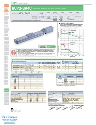
- 1. ■ Speed vs. Load Capacity Due to the characteristics of the pulse motor, the RCP3 series' load capacity decreases at high speeds. In the table below, check if your desired speed and load capacity are supported. 12 10 8 6 4 2 0 0 100 200 300 400 500 600 9 7.5 6 4.5 3 1.5 RCP3 ROBO Cylinder I: Incremental * The Simple absolute encoder models are labeled as "I". 35P: Pulse motor 35 □ size (1) Since the RCP3 series use a pulse motor, a load capacity decreases at high speeds. Check in the Speed vs. Load Capacity graph to see if your desired speed and load capacity are supported. (2) The load capacity is based on operation at an acceleration of 0.3G (0.2G for 2.5 mm-lead model, or when used vertically). The maximum acceleration is 0.7G (0.3G when used vertically), however, note that the load capacity decreases at high accelerations. For more information, see the table of load capacity by acceleration, on page A-50. O I N Actuator Specifications ■ Lead and Load Capacity ■ Stroke and Maximum Speed Max. Load Capacity Maximum Legend 1 Stroke 2 Compatible controller 3 Cable length 4 Options (Unit: mm/s) Type Cable Symbol Standard Price Standard (Robot Cables) Special Lengths Actuator Specifications Item Description Drive System Positioning Repeatability Lost Motion Base Allowable Static Moment Allowable Dynamic Moment(*) Overhang Load Length Ambient Operating Temp./Humidity (*) Based on 5,000km travel life. Speed (mm/s) Load capacity (kg) Horizontal 10mm lead 11 2.5mm lead 9 7.5 7 3 5mm lead 0 0 100 200 300 400 500 600 Speed (mm/s) Load capacity (kg) Vertical 10mm lead 8 2.5mm lead 4 2.5 0.5 5mm lead 1 Stroke List 3 Cable List Stroke (mm) 50 100 150 200 250 300 350 400 450 500 4 Option List P T Notes on Selection Stroke Lead 50 ~ 500 (50mm increments) 500 250 125 10 5 2.5 Technical References A-5 Lead (mm) 10 5 2.5 Horizontal (kg) ~ 7.5 ~ 9 ~ 11 Vertical (kg) Push Force (N) Model ~ 1.5 ~ 4 ~ 8 34 68 136 Stroke (mm) RCP3-SA4C-I-35P-10- 1 - 2 - 3 - 4 RCP3-SA4C-I-35P-5- 1 - 2 - 3 - 4 RCP3-SA4C-I-35P-2.5- 1 - 2 - 3 - 4 50~500 (50mm increments) P (1m) S (3m) M (5m) X06 (6m) ~ X10 (10m) X11 (11m) ~ X15 (15m) X16 (16m) ~ X20 (20m) * See page A-39 for cables for maintenance. – – – – – – Ball screw Ø8mm C10 grade ±0.02mm 0.1mm or less Material: Aluminum (special alumite treated) Ma: 6.8N∙m Mb: 9.7N∙m Mc: 13.3 N∙m Ma: 3.04N∙m Mb: 4.31N∙m Mc: 5.00N∙m 120mm or less 0~40°C, 85%RH or less (Non-condensing) Directions of Allowable Load Moment Overhang Load Length L L Ma Mb Mc Ma Mc With cover (standard) No cover (Option) – – – – – – – – – – – – – – – – – – – – Standard Price Name Option Code See Page Standard Price Brake-Equipped B → A-25 — Cable Exit Direction (Top) CJT → A-25 — Cable Exit Direction (Right) CJR → A-25 — Cable Exit Direction (Left) CJL → A-25 — Cable Exit Direction (Bottom) CJB → A-25 — No Cover NCO → A-33 — Reversed-home NM → A-33 — 9 RCP3-SA4C Slider Type Mini Standard Controllers Integrated Rod Type Mini Standard Controllers Integrated Table/Arm /Flat Type Mini Standard Gripper/ Rotary Type Linear Servo Type Cleanroom Type Splash-Proof Controllers PMEC /AMEC PSEP /ASEP ROBO NET ERC2 PCON ACON SCON PSEL ASEL SSEL XSEL Pulse Motor Servo Motor (24V) Servo Motor (200V) Linear Servo Motor RCP3-SA4C ROBO Cylinder Slider Type 40mm Width Pulse Motor Coupled * See page Pre-35 for explanation of each code that make up the configuration name. P1: PCON RPCON PSEL P3: PMEC PSEP 10 : 10mm 5 : 5mm 2.5 : 2.5mm ■ Configuration: RCP3 SA4C I 35P Series Type Encoder Motor Lead Stroke Compatible Controllers Cable Length Option 50: 50mm 〜 500: 500mm (50mm pitch increments) N : None See Options below P : 1m S : 3m M : 5m X □□ : Custom Length Sold & Serviced By: ELECTROMATE Toll Free Phone (877) SERVO98 Toll Free Fax (877) SERV099 www.electromate.com sales@electromate.com
- 2. (With Cover) 2.5H7 depth 5 from bottom of base 3.5 38 65 21 14±0.02 4-M3 depth 6 2-ø2.5H7 depth 5 A 93.5 A 93.5 ø2.5H7 depth 5 from bottom of base 37 40 21 14±0.02 26 37 RCP3 ROBO Cylinder ■ Dimensions/Weight by Stroke * Brake-equipped models are heavier by 0.3kg. Stroke 50 100 150 200 250 300 350 400 450 500 No Brake Brake-Equipped 2 Compatible Controllers The RCP3 series actuators can operate with the controllers below. Select the controller according to your usage. 40.5 If equipped with a brake F D-M3 depth 5 21 10.5 15 Cx100 (M3 tap) B 15 Above motor cover: 51 26 5.2 5.2 48 37 5 40 Detail F 4-M3 depth 6 2-ø2.5H7 depth 5 Above motor cover: 51 5.2 5.2 48 37 5 40 Motor-encoder cable connector (*1) (With Cover) (No Cover) (No Cover) A M (ø2.5 hole and oblong hole pitch) * The above brake unit ( is added to A. ) Secure at least 100 2200±±00..0022 20±0.02 Change cable outlet direction (optional) (Left: CJL) * When viewed from arrow B. (Top: CJT) (Bottom: CJB) (Right: CJR) Secure at least 100 B 36.5 Reference position for Ma moment offset (*3) 36.5 Reference position for Ma moment offset (*3) 25 32 32 ME SE Home ME (*2) 33.5 L 10 23 st 26 23 3 3 ME SE Home ME (*2) 33.5 L 10 23 st 26 23 3 3 Dimensions (*1) A Motor-encoder cable (integrated) is connected here. (See page A-39 for details on cables.) (*2) After homing, the slider moves to the ME, therefore, please watch for any interference with surrounding objects. ME : Mechanical end SE : Stroke end (*3) Reference position for calculating the moment Ma. For Special Order P. A-9 Name External View Model Description Max. Positioning Points Input Voltage Power Supply Capacity Standard Price See Page Solenoid Valve Type PMEC-C-35PI-NP-2-1 Easy-to-use controller, even for beginners 3 points AC100V AC200V See P481 — → P477 PSEP-C-35PI-NP-2-0-H Operable with same signal as solenoid valve. Supports both single and double solenoid types. No homing necessary with simple absolute type. DC24V 2A Max. — → P487 Splash-Proof Solenoid Valve Type PSEP-CW-35PI-NP-2-0-H — Positioner Type PCON-C-35PI-NP-2-0-H Positioning is possible for up to 512 points 512 points — → P525 Safety-Compliant Positioner Type PCON-CG-35PI-NP-2-0-H — Pulse Train Input Type (Differential Line Driver) PCON-PL-35PI-NP-2-0-H Pulse train input type with differential line driver support (−) — Pulse Train Input Type (Open Collector) PCON-PO-35PI-NP-2-0-H Pulse train input type with open collector support — Serial Communication Type PCON-SE-35PI-N-0-0-H Dedicated to serial communication 64 points — Field Network Type RPCON-35P-H Dedicated to field network 768 points — → P503 Program Control Type PSEL-C-1-35PI-NP-2-0-H Programmed operation is possible. Can operate up to 2 axes 1500 points — → P557 * This is for the single-axis PSEL. * 1 is a placeholder for the power supply voltage (1: 100V / 2: 100~240V). A B C D M L Weight (kg) With Cover No Cover 259 299.5 165.5 91 0 4 91 309 349.5 215.5 41 1 6 141 359 399.5 265.5 91 1 6 191 409 449.5 315.5 41 2 8 241 459 499.5 365.5 91 2 8 291 509 549.5 415.5 41 3 10 341 559 599.5 465.5 91 3 10 391 609 649.5 515.5 41 4 12 441 659 699.5 565.5 91 4 12 491 709 749.5 615.5 41 5 14 541 0.9 0.9 1 0.9 1.1 1 1.2 1.1 1.3 1.2 1.4 1.2 1.5 1.3 1.6 1.4 1.7 1.5 1.8 1.5 RCP3-SA4C 10 Slider Type Mini Standard Controllers Integrated Rod Type Mini Standard Controllers Integrated Table/Arm /Flat Type Mini Standard Gripper/ Rotary Type Linear Servo Type Cleanroom Type Splash-Proof Controllers PMEC /AMEC PSEP /ASEP ROBO NET ERC2 PCON ACON SCON PSEL ASEL SSEL XSEL Pulse Motor Servo Motor (24V) Servo Motor (200V) Linear Servo Motor CAD drawings can be downloaded from IAI website. www.intelligentactuator.com Sold & Serviced By: ELECTROMATE Toll Free Phone (877) SERVO98 Toll Free Fax (877) SERV099 www.electromate.com sales@electromate.com