SlideShare a Scribd company logo
1 of 7
Download to read offline
High Power Digital to Synchro & Amplifier 
Features 
25, 30, 50, 100, and up to 300 VA Models 
60 or 400, & 60 and 400 Hz. Models 
25 VA Units Deliver 100 VA + Peak Drive 
Trouble Free Isolated Inputs & Outputs 
Ultra High Efficiency, Low Distortion 
Self Powered off the AC Reference Input 
Internal Cool AC-Pulsating Supplies 
Very Low Loss & Heat Dissipation 
Simple Bulkhead/Backplane Mount 
Very High Resistance to Shock and Vibration 
High Reliability Throughout Implementation 
Built in Kick to Free Stalled Rotors 
Thermal and Overload Sense & BIT Report 
Output Enable & Circuit Safe Disable Control 
Transient & Short Circuit Protected Outputs 
NO EXTERNAL SUPPLIES REQUIRED! 
100% REFERENCE POWERED 
DRIVES ALL SYNCHRO LOADS 
Description 
The SPA Series “Pulsating” Synchro Power Amplifiers, and DSPH Series High Power 
Digital to Synchro Converters, are proven, high efficiency, low cost, compact, reliable 
solid state synchro drivers; designed for demanding Naval/Maritime, Aircraft, fire 
control and Radar/Antenna related applications. They are commonly used on 
synchro based data transmission, retransmission, simulation, and 
instantaneous absolute position indicating and active control systems. 
The SPA series accepts any 3 wire synchro, or 4 wire sine/cosine resolver inputs. The 
DSPH Series accept up to 16 bits of parallel binary data inputs, either providing an 
efficient high power 3 wire synchro output, capable of driving direct and multiple large 
synchro loads. Models range from 25VA and 30VA continuous/ 100VA peak, 
50VA/200VA peak, 100VA/400VA peak, selections standard product, and up to 
300VA100+VA peak units can be provided on special applications. 
All models are completely powered from the AC reference input, eliminating the need 
for any large and very expensive (heat generating) linear DC supplies 
Installation is easy: in most synchro booster-amplifier, repeater, and retransmission 
applications, simply treat it like a synchro; mount it, wire your 5 synchro source leads, 
3 synchro destination leads, and your running! 
For high power D-S applications; the digital to synchro converter is built into and 
completely powered by the amp. To install D-S units, simply apply your 14 or 16 bit 
digital TTL data in lieu of a synchro input and you’re running. The input is continuous, 
and the input to output throughput is less than 100 Usec. D-S options include: Data 
Latch inputs for synchronous or strobed data transfer and high-byte/low byte 
latched enable inputs for use with either an 8 or 16 bit data bus. 
1 of 7 
Sold & Serviced By: 
ELECTROMATE 
Toll Free Phone (877) SERVO98 
Toll Free Fax (877) SERV099 
www.electromate.com 
sales@electromate.com
Dynamic Power Supply 
The outputs are powered by an internal, transformer isolated, purely AC dynamic power 
supply that efficiently transfers the AC reference input power to the outputs, in a natural 
AC flowing format yielding very low loss. 
The power supply produces unfiltered, full-wave rectified positive and negative voltages. 
These voltages are always in phase with the amplifier output voltages since the power is 
derived from the reference input. Optimum efficiency is achieved by essentially using 
as much AC direct power transfer as possible to drive the AC outputs because there is no 
DC conversion in the power transfer and the amplitude of the internal AC power rails need 
only be a few volts greater than the voltages driven on the outputs. 
Because the outputs are allowed to follow the reference input (synchro’s and converters use 
ratio accuracy), these supplies only need to be a small percentage higher in voltage than the 
amplifiers maximum output voltage to accommodate the headroom required of the circuit. 
The lower the voltage differential required input to output (considering the internal 
transformers), to drive the load; the minimum the power loss (in the form of heat), and the 
greater the efficiency of the amp. 
2 of 7 
Sold & Serviced By: 
ELECTROMATE 
Toll Free Phone (877) SERVO98 
Toll Free Fax (877) SERV099 
www.electromate.com 
sales@electromate.com
Using this AC pulsating power technique, the output signals are tightly coupled to the reference 
input and the only power dissipated is the current times the small voltage difference between 
the pulsating power stage and the synchro signal outputs. 
Because both the power stage and the signal outputs are sinusoidal, and the power stages 
headroom is very small, the power required to drive the load is minimal. Thus the Reference 
Powered Synchro Amplifiers provide the highest efficiency attainable, low loss, 
and minimum heat dissipation. 
Because there is no internal high frequency PWM or charge-pump switching, there is no RF 
switching noise emitted from the unit or discontinuity in the outputs to compromise other 
user circuits, and the outputs are inherently compatible with all and any existing synchro 
converters. 
Using this type of “dynamic power transfer technique,” the efficiency is nominally better than 
80% and loss (power dissipation & heat generation) for reactive loads is less than half that 
of conventional DC powered amplifiers. 
Care should be take to minimize the phase shift between the reference and signal inputs. Since 
the power supplies are only a few volts greater than the signal, the output could be affected by 
phase shift. Phase shift effect, compensation, and management techniques are detailed in 
CCC ap.note#G-SA1 “Driving Synchro Loads.” 
Packaging/Conductive Cooling 
These models are all self-contained in an easy to install “Bolt-On” bulkhead mount chassis. The 
chassis is a light weight, single piece aluminum 1/8” thick solid base plate, that provides 
excellent thermal transfer for conductive cooling of the unit. 
Mounting and Thermal Considerations: 
Since the unit is primarily conduction cooled, make sure that it is tightly mounted to an 
appropriately large, thermally conductive (unpainted) surface. Thermal grease can also be 
applied to the mounting surface. 
Kick Circuit 
For Torque Receiver applications, a kick circuit is provided to free stalled rotors, simply wire a 
jumper between the “CO” (current overload) output, and the “Kick” input. 
3 of 7 
Sold & Serviced By: 
ELECTROMATE 
Toll Free Phone (877) SERVO98 
Toll Free Fax (877) SERV099 
www.electromate.com 
sales@electromate.com
More common an occurrence with large digital or switched step inputs, or after power up; a 
synchro torque receiver may get hung up at a false null, and just sit there and vibrate while 
draining large circulating currents. The amplifier will sense the overload that occurs if the rotor is 
persistently drawing too much current trying (unsuccessfully) to move the shaft load, and (with 
the kick/CO jumper installed) the amp will automatically shift the output by 120 degrees for a 
nominal 1/2 second duration to free the rotor from the false null. 
Once the rotor is put in motion, it has greater control of its output. Use this feature only if at least 
one Torque Receiver is being driven from the outputs. 
Disable Input 
The disable input is a TTL compatible Opto-Isolated input used to provide a circuit-safe means 
of disabling (turning off & on) the amplifier outputs for various applications. When disabled, the 
outputs appear as an open circuit to the load. 
The disable can be used to sequentially power up the synchro amps if several are used in a 
power sensitive application, or when used where the synchro signal outputs are going through 
switching relays for auxiliary, back-up, or test systems. 
The disabling the outputs prior to switching either the reference/power inputs or the stator 
outputs, or both, and then driving the synchro amp inputs to match the angle dictated on the 
destination source prior enabling the outputs. The relays can very safely switch these points 
without any appreciable power demand during the actual switching. This will provide a very 
smooth transition that will reduce surges, and inductive content, allowing the user to minimize 
the required size of the relays, and dramatically increase the life of any relays used for switching 
these (high power) terminations. A logic 1 is used to disable the power outputs, a logic 0 will will 
enable the outputs providing the unit is powered and is not in a thermal overload sensed 
condition. 
BIT Output 
The Built-in-test output is a TTL compatible Opto-Isolated output that uses a logic level 1 to 
indicate that the amplifier has sensed either a thermal overload condition forcing it to shut down 
its outputs until the internal temperature cools down, or a current overload that is straining and 
thereby distorting the outputs, until the load is recovered (or kicked to free a stalled rotor), or if 
in thermal overload (when the internal temperatures sense shuts down the outputs). 
Current-Load Sense 
The output current on 25VA units is limited to 1.0 amp peak, and approximately 1 amp/25VA on 
larger units, after a 4 second nominal delay; an over current indication is sensed, setting the 
BIT output to a logic 1 (see Built-in-test, above). 
When Driving Torque Receivers, the current limiting is typically experience whenever the rotor is 
off null (any significant difference in angle, from where it is being commanded to go), 
typically activating the kick circuit to rapidly set the driven synchro in motion (to free the rotor 
from hang-up), allowing the rotor to move towards its commanded angle (=null). 
Thermal Sense 
These synchro amplifiers are thermally protected, the amplifier outputs will shut down when 
the internal temperature reaches 125oC, also setting the BIT output to a logic 1. 
Thermal overload recovers when the internal temperature recovers. 
~~~~~~~~~~~~~~~~~~~~SPECIFICATIONS:~~~~~~~~~~~~~~~~~~~~ 
Digital Inputs/Outputs: (All Units) 
*Disable...Input (DIS): Logic “0” = L=OVDC Enables Power Amplifier Output, TTL Compatible, 
requires 2.5ma. at logic 0 
**Isolation: OptoIsolated - 1000V Peak min. Breakdown voltage to Ground. 
4 of 7 
Sold & Serviced By: 
ELECTROMATE 
Toll Free Phone (877) SERVO98 
Toll Free Fax (877) SERV099 
www.electromate.com 
sales@electromate.com
Built-in-test: Output, Overload Indicator (BIT): logic level 1=H, drives 2 TTL loads, 
indicates amplifier sensed over load condition forcing it to shut down its 
outputs until conditions are satisfied (see txt). 
* Providing unit is not in thermal overload; internal Temperature is less 
than 125oC. 
1. 
* Synchro Outputs when disabled 2. are as open circuit, high impedance state. 
** On D-S units (having internal Digital to Synchro Converter); no external 
+5VDC is required, uses internal isolated +5VDC supply, the +5VRTN (see block 
dia.) is same as the digital data common only. 
3. 
**Isolation: OptoIsolated - 1000V Peak min. Breakdown voltage to Ground. 
Kick Circuit: Kick & CO (Kick input & current over load); are normally connected for Torque 
Receiver Loads (not for Passive CT of CDX loads); If Output is hung-up due to excessive 
current output; Shifts output 120o for .5 sec. to unjam rotor hang-up. (see txt). 
Notes: 
Signal Inputs: 
(A) Synchro: 90VL-L 400Hz +10% (400 Hz) 
Impedence = 400K Ohms min. balanced 
(A) Synchro: 90V L-L 60Hz +5 % (60 & 60/400 Hz) 
Impedence = 100K Ohms min balanced 
(D) Synchro: 11.8V L-L 400Hz +10% 
Impedence = 26K Ohms min. balanced 
(B) **Resolver: 6.81V L-L @ 400Hz or 60Hz +10 % 
Impedence = 4K Ohms min balanced 
(C) ***Resolver: 6.0V L-L @ 400Hz or 60Hz +10% 
Impedence = 4K Ohms min balanced 
Notes: 
*1) P/N Codes See Model Selection Guide 
**2) Typical Resolver Input format for synchro outputs: when driven by a D-R converter 
operating on +15 VDC supplies. 
***3)When driven by a D-R converter operating on +12 VDC supplies. 
Signal Input Isolation: 
Internally Transformer Isolated; 500VDC min. Breakdown Voltage to Gnd. 
DC Power Input for BIT/EN Opto-Isolators: 
+5V DC.+10% @ 10ma MAX. 
(Not required on -P units, add a P to end of P/N) 
Synchro Outputs: 
Synchro Output: 90V. Output Models: 90V L-L +1%: 
25VA Models: Drives Zso = 243 Ohms (Passive CT & CDX type loads) 
Drives Zss = 6 Ohms (Active Torque Receiver type loads 30VA 
Models: Drives Zso = 202 Ohms, Zss 6 Ohms 
50VA Models: Drives Zso = 122 Ohms, Zss 3 Ohms 
100VA Models: Drives Zso = 61 Ohms, Zss 1.5 Ohms 
Synchro Output: 11.8V. Output Models: 11.8V L-L +1%: 
15VA Models: Drives Zso = 6.9 Ohms 
25VA Models: Drives Zso = 4.2 Ohms 
5 of 7 
Sold & Serviced By: 
ELECTROMATE 
Toll Free Phone (877) SERVO98 
Toll Free Fax (877) SERV099 
www.electromate.com 
sales@electromate.com
*ACCURACY: 
+3 arc. minutes for passive CT & CDX loads 
+6 arc. minutes typical, +10 arc. minutes worse case for active aTorque 
Receiver (TR) type loads. 
*Shown for Synchro Amplifier Types, for internal 14 bit D-S add 4, 16 bit 
add 2, arc. minutes. 
*Reference Power Input:(Amplifiers) 
**90V. Signals, 25VA Models: 
(400 Hz.) 115V. RMS +10%, 360-440 Hz. @ 60 ma.** 
(60 Hz.) 115V. RMS +10%, 57-63 Hz. @ 100 ma.** 
(60 & 400) 115V. RMS +10%, 57-440 Hz. @ 100 ma.** 
90V. Signals, 60 Hz. 100VA Model: (Typical/Measured) 
725 ma. no load, +1.122ma. of input/ma. of output. 
**11.8V. Signals, 25VA Models: 
(400 Hz.) 26V. RMS +10%, 360-440 Hz. @ n1 ma. 
(No load) plus n2 ma. per ma. of output load. 
TEMPERATURE: (BEST IN CLASS!) 
Operating Temperature Range: -40oC to +85oC 
Storage Temperature Range: -55oC to +125oC 
Heat Dissipation:1.5 watts/VA to load. (25 & 30VA.) 
Notes: 
* Reference 1. input must be in phase with signal inputs and signal outputs. 
2. ** (No load) plus 1 ma. per ma. of output load. 
3. 25VA units; 1 A. typ. draw w/output short circuit. 
MODEL SELECTION GUIDE FOR SYNCHRO POWER BOOSTERS (AMPLIFIERS) 
MODEL 
Option 
Internal 
+5VDC 
used for 
EN/BIT 
Output 
POWER 
VA 
Frequency 
INPUTS-POWER & SIGNALS OUTPUTS WEIGHT SIZE 
Reference & 
POWER 
INPUTS 
SIGNAL 
INPUTS 
V.L-L Balanced 
SIGNAL 
INPUT 
FORMAT 
SYN/RES 
Synchro 
Format in 
V.L-L 
Balanced 
WEIGHT 
Package 
Drawing 
Code 
SPA2560-A -P 
25VA 60Hz. 115VAC 
90V.L-L Synchro 
90V.L-L 4.75 lbs. B 
SPA2560-B -P 6.81V.L-L Resolver 7.4”Lx2.6”H 
SPA2560-C -P 6.0V.L-L Sin/Cos 
SPA2540-D-P included 
25VA 400Hz. 
26/115VAC 11.8 Synchro 11.8V.L-L 3.25 lbs. 
A 
5.09”W x 
7.4”Lx1.84”H 
SPA2540-A -P 
115VAC 
90 Synchro 
SPA2540-B -P 6.81V.L-L Resolver 90V.L-L 3.25 lbs. 
SPA2540-C -P 6.0V.L-L Sin/Cos 
SPA25B-A -P 
25VA 
BOTH 
60 or 
400Hz. 
115VAC 
90 Synchro 
90V.L-L 4.75 lbs. B 
SPA25B-B -P 6.81V.L-L Resolver 7.4”Lx2.6”H 
SPA25B-C -P 6.0V.L-L Sin/Cos 
SPA3060-A -P 
30VA 60Hz. 115VAC 
90 Synchro 
90V.L-L 
4.75 
lbs. 
B 
SPA3060-B -P 6.81V.L-L Resolver 7.4”Lx2.6”H 
SPA3060-C -P 6.0V.L-L Sin/Cos 
SPA3040-A -P 
30VA 400Hz. 115VAC 
90 Synchro 
90V.L-L 4.75 lbs. A 
SPA3040-B -P 6.81V.L-L Resolver 7.4”Lx1.84”H 
Sin/Cos 
Sold & Serviced By: 
SPA3040-C -P 6.0V.L-L 
SPA5060-A -P 50VA 60Hz. 115VAC 90 Synchro 90V.L-L 7.0 lbs. C 
6 of 7 
ELECTROMATE 
Toll Free Phone (877) SERVO98 
Toll Free Fax (877) SERV099 
www.electromate.com 
sales@electromate.com
5.1”W x 
9.31”L x 
2.75”H 
SPA5060-B -P 6.81V.L-L Resolver 
SPA5060-C -P 6.0V.L-L Sin/Cos 
SPA1040-A -P 
100VA 400Hz. 115VAC 
90 Synchro 
90V.L-L 5.75 lbs. 
C 
5.1”W x 
9.31”L x 
2.75”H 
SPA1040-B -P 6.81V.L-L Resolver 
SPA1040-C -P 6.0V.L-L Sin/Cos 
SPA1060-A -P 
100VA 60Hz. 115VAC 
90 Synchro 
90V.L-L 8.0 lbs. 
D 
5.1”W x 
9.31”L x 
3.31”H 
SPA1060-B -P 6.81V.L-L Resolver 
SPA1060-C -P 6.0V.L-L Sin/Cos 
SPA10B-A -P 
100VA 
BOTH 
60 OR 
400Hz. 
115VAC 
90 Synchro 
90V.L-L 8.0 lbs. 
D 
5.1”W x 
9.31”L x 
3.31”H 
SPA10B-B -P 6.81V.L-L Resolver 
SPA10B-C -P 6.0V.L-L Sin/Cos 
400Hz. 115VAC 6.81V.L-L Resolver 
SPB2054-52-B -P 200VA 50,60 OR 
Sin/Cos 52V.L-L 32.0 lbs. 
C7972 
8.8”W x 
15.0”L x 
3.7”H 
Notes: 
1. Add -P to end of model # for units with internal +5VDC power supply, (no external supplies required). 
2. Use 6.81V. signal inputs when driven by Bus Cards PCI, VME, D-S cards using +15VDC supplies. 
3. Use 6.0V. signal inputs when driven with Bus Cards PCI, VME, D-S cards using +12VDC supplies. 
4. Use E in part number in lieu of -A, -B, -C, when driven by our cPCI Cards. 
CCC app.note #G-SA1 
“Driving Synchro Loads” 
Request Full Data Sheet 
Copyright © 2012 
7 of 7 
Sold & Serviced By: 
ELECTROMATE 
Toll Free Phone (877) SERVO98 
Toll Free Fax (877) SERV099 
www.electromate.com 
sales@electromate.com

More Related Content

What's hot

Power supplies & regulators
Power supplies & regulatorsPower supplies & regulators
Power supplies & regulatorsDr.YNM
 
Inverter design ppt
Inverter design pptInverter design ppt
Inverter design pptsubarna Giri
 
4.inverter final
4.inverter final4.inverter final
4.inverter finalAshu0711
 
Comparision of power electronic devices
Comparision of power electronic devicesComparision of power electronic devices
Comparision of power electronic devicesVarikuppala Sangeetha
 
Statics switches
Statics switchesStatics switches
Statics switcheskrunal103
 
Power Electronics SCR and BJT MCQ Questions
Power Electronics SCR and BJT MCQ QuestionsPower Electronics SCR and BJT MCQ Questions
Power Electronics SCR and BJT MCQ QuestionsBurdwan University
 
Subtech:Automatic Changeover,ACCL, AMF Panel, Motor Starter etc.
Subtech:Automatic Changeover,ACCL, AMF Panel, Motor Starter etc.Subtech:Automatic Changeover,ACCL, AMF Panel, Motor Starter etc.
Subtech:Automatic Changeover,ACCL, AMF Panel, Motor Starter etc.latesh sharma
 
Advanced motion controls 10a8
Advanced motion controls 10a8Advanced motion controls 10a8
Advanced motion controls 10a8Electromate
 
Electrical basics of Switch yard Protection Relays and Electrical basics and ...
Electrical basics of Switch yard Protection Relays and Electrical basics and ...Electrical basics of Switch yard Protection Relays and Electrical basics and ...
Electrical basics of Switch yard Protection Relays and Electrical basics and ...Malaiyappasamy Sivashanmugam
 
Automatic load sharing of transformer using microcontroller
Automatic load sharing of transformer using microcontrollerAutomatic load sharing of transformer using microcontroller
Automatic load sharing of transformer using microcontrollerPrakhar Anand
 
Ic voltage regulators
Ic voltage regulatorsIc voltage regulators
Ic voltage regulatorsAnita Thattil
 
Advanced motion controls 30a8i
Advanced motion controls 30a8iAdvanced motion controls 30a8i
Advanced motion controls 30a8iElectromate
 

What's hot (20)

Power supplies & regulators
Power supplies & regulatorsPower supplies & regulators
Power supplies & regulators
 
Inverter design ppt
Inverter design pptInverter design ppt
Inverter design ppt
 
Ats brochure
Ats brochureAts brochure
Ats brochure
 
4.inverter final
4.inverter final4.inverter final
4.inverter final
 
Fan regulator
Fan regulatorFan regulator
Fan regulator
 
Comparision of power electronic devices
Comparision of power electronic devicesComparision of power electronic devices
Comparision of power electronic devices
 
Statics switches
Statics switchesStatics switches
Statics switches
 
Self Switching Power Supply
Self Switching Power SupplySelf Switching Power Supply
Self Switching Power Supply
 
Power supply
Power supplyPower supply
Power supply
 
Power Electronics SCR and BJT MCQ Questions
Power Electronics SCR and BJT MCQ QuestionsPower Electronics SCR and BJT MCQ Questions
Power Electronics SCR and BJT MCQ Questions
 
Subtech:Automatic Changeover,ACCL, AMF Panel, Motor Starter etc.
Subtech:Automatic Changeover,ACCL, AMF Panel, Motor Starter etc.Subtech:Automatic Changeover,ACCL, AMF Panel, Motor Starter etc.
Subtech:Automatic Changeover,ACCL, AMF Panel, Motor Starter etc.
 
Inverter
InverterInverter
Inverter
 
Advanced motion controls 10a8
Advanced motion controls 10a8Advanced motion controls 10a8
Advanced motion controls 10a8
 
Electrical basics of Switch yard Protection Relays and Electrical basics and ...
Electrical basics of Switch yard Protection Relays and Electrical basics and ...Electrical basics of Switch yard Protection Relays and Electrical basics and ...
Electrical basics of Switch yard Protection Relays and Electrical basics and ...
 
Automatic load sharing of transformer using microcontroller
Automatic load sharing of transformer using microcontrollerAutomatic load sharing of transformer using microcontroller
Automatic load sharing of transformer using microcontroller
 
Ic voltage regulators
Ic voltage regulatorsIc voltage regulators
Ic voltage regulators
 
Inverters
InvertersInverters
Inverters
 
Inverter
InverterInverter
Inverter
 
Basics of Power Inverters
Basics of Power InvertersBasics of Power Inverters
Basics of Power Inverters
 
Advanced motion controls 30a8i
Advanced motion controls 30a8iAdvanced motion controls 30a8i
Advanced motion controls 30a8i
 

Viewers also liked

Inertia dynamics sheave_clutches_specsheet
Inertia dynamics sheave_clutches_specsheetInertia dynamics sheave_clutches_specsheet
Inertia dynamics sheave_clutches_specsheetElectromate
 
Advanced motion controls dpcanis 060a800
Advanced motion controls dpcanis 060a800Advanced motion controls dpcanis 060a800
Advanced motion controls dpcanis 060a800Electromate
 
Bayside ps gearheads_catalog
Bayside ps gearheads_catalogBayside ps gearheads_catalog
Bayside ps gearheads_catalogElectromate
 
Iai robo cylinder_controller_catalog
Iai robo cylinder_controller_catalogIai robo cylinder_controller_catalog
Iai robo cylinder_controller_catalogElectromate
 
Iai rcp4 w_specsheet
Iai rcp4 w_specsheetIai rcp4 w_specsheet
Iai rcp4 w_specsheetElectromate
 
Bayside rs gearheads_catalog
Bayside rs gearheads_catalogBayside rs gearheads_catalog
Bayside rs gearheads_catalogElectromate
 
Gam spiral bevel brochure
Gam spiral bevel brochureGam spiral bevel brochure
Gam spiral bevel brochureElectromate
 
Advanced motion controls b100a20
Advanced motion controls b100a20Advanced motion controls b100a20
Advanced motion controls b100a20Electromate
 
Advanced motion controls dpcanie c100a400
Advanced motion controls dpcanie c100a400Advanced motion controls dpcanie c100a400
Advanced motion controls dpcanie c100a400Electromate
 
Advanced motion controls b50a8
Advanced motion controls b50a8Advanced motion controls b50a8
Advanced motion controls b50a8Electromate
 
Beijer inverter e2_brochure
Beijer inverter e2_brochureBeijer inverter e2_brochure
Beijer inverter e2_brochureElectromate
 
Delta c200 catalog
Delta c200 catalogDelta c200 catalog
Delta c200 catalogElectromate
 
Iai rs 3_a_specsheet
Iai rs 3_a_specsheetIai rs 3_a_specsheet
Iai rs 3_a_specsheetElectromate
 
Advanced motion controls dpcanis 060a400
Advanced motion controls dpcanis 060a400Advanced motion controls dpcanis 060a400
Advanced motion controls dpcanis 060a400Electromate
 
Bayside pv gearhead_brochure
Bayside pv gearhead_brochureBayside pv gearhead_brochure
Bayside pv gearhead_brochureElectromate
 
Gam sph brochure
Gam sph brochureGam sph brochure
Gam sph brochureElectromate
 
Advanced motion controls dpcanie 060a800
Advanced motion controls dpcanie 060a800Advanced motion controls dpcanie 060a800
Advanced motion controls dpcanie 060a800Electromate
 
Advanced motion controls bd15a8
Advanced motion controls bd15a8Advanced motion controls bd15a8
Advanced motion controls bd15a8Electromate
 

Viewers also liked (19)

Inertia dynamics sheave_clutches_specsheet
Inertia dynamics sheave_clutches_specsheetInertia dynamics sheave_clutches_specsheet
Inertia dynamics sheave_clutches_specsheet
 
Wago catalog
Wago catalogWago catalog
Wago catalog
 
Advanced motion controls dpcanis 060a800
Advanced motion controls dpcanis 060a800Advanced motion controls dpcanis 060a800
Advanced motion controls dpcanis 060a800
 
Bayside ps gearheads_catalog
Bayside ps gearheads_catalogBayside ps gearheads_catalog
Bayside ps gearheads_catalog
 
Iai robo cylinder_controller_catalog
Iai robo cylinder_controller_catalogIai robo cylinder_controller_catalog
Iai robo cylinder_controller_catalog
 
Iai rcp4 w_specsheet
Iai rcp4 w_specsheetIai rcp4 w_specsheet
Iai rcp4 w_specsheet
 
Bayside rs gearheads_catalog
Bayside rs gearheads_catalogBayside rs gearheads_catalog
Bayside rs gearheads_catalog
 
Gam spiral bevel brochure
Gam spiral bevel brochureGam spiral bevel brochure
Gam spiral bevel brochure
 
Advanced motion controls b100a20
Advanced motion controls b100a20Advanced motion controls b100a20
Advanced motion controls b100a20
 
Advanced motion controls dpcanie c100a400
Advanced motion controls dpcanie c100a400Advanced motion controls dpcanie c100a400
Advanced motion controls dpcanie c100a400
 
Advanced motion controls b50a8
Advanced motion controls b50a8Advanced motion controls b50a8
Advanced motion controls b50a8
 
Beijer inverter e2_brochure
Beijer inverter e2_brochureBeijer inverter e2_brochure
Beijer inverter e2_brochure
 
Delta c200 catalog
Delta c200 catalogDelta c200 catalog
Delta c200 catalog
 
Iai rs 3_a_specsheet
Iai rs 3_a_specsheetIai rs 3_a_specsheet
Iai rs 3_a_specsheet
 
Advanced motion controls dpcanis 060a400
Advanced motion controls dpcanis 060a400Advanced motion controls dpcanis 060a400
Advanced motion controls dpcanis 060a400
 
Bayside pv gearhead_brochure
Bayside pv gearhead_brochureBayside pv gearhead_brochure
Bayside pv gearhead_brochure
 
Gam sph brochure
Gam sph brochureGam sph brochure
Gam sph brochure
 
Advanced motion controls dpcanie 060a800
Advanced motion controls dpcanie 060a800Advanced motion controls dpcanie 060a800
Advanced motion controls dpcanie 060a800
 
Advanced motion controls bd15a8
Advanced motion controls bd15a8Advanced motion controls bd15a8
Advanced motion controls bd15a8
 

Similar to Computer conversion s_synchro_amplifiers_specsheet

Advanced motion controls s30a40ac
Advanced motion controls s30a40acAdvanced motion controls s30a40ac
Advanced motion controls s30a40acElectromate
 
Advanced motion controls s60a40ac
Advanced motion controls s60a40acAdvanced motion controls s60a40ac
Advanced motion controls s60a40acElectromate
 
Advanced motion controls azbh20a8
Advanced motion controls azbh20a8Advanced motion controls azbh20a8
Advanced motion controls azbh20a8Electromate
 
Advanced motion controls s60a40
Advanced motion controls s60a40Advanced motion controls s60a40
Advanced motion controls s60a40Electromate
 
Advanced motion controls s30a40
Advanced motion controls s30a40Advanced motion controls s30a40
Advanced motion controls s30a40Electromate
 
Advanced motion controls ab250a060
Advanced motion controls ab250a060Advanced motion controls ab250a060
Advanced motion controls ab250a060Electromate
 
Advanced motion controls s100a40ac
Advanced motion controls s100a40acAdvanced motion controls s100a40ac
Advanced motion controls s100a40acElectromate
 
Advanced motion controls azbh40a8
Advanced motion controls azbh40a8Advanced motion controls azbh40a8
Advanced motion controls azbh40a8Electromate
 
Advanced motion controls ab100c200
Advanced motion controls ab100c200Advanced motion controls ab100c200
Advanced motion controls ab100c200Electromate
 
Advanced motion controls azbh10a20
Advanced motion controls azbh10a20Advanced motion controls azbh10a20
Advanced motion controls azbh10a20Electromate
 
Advanced motion controls 100a25
Advanced motion controls 100a25Advanced motion controls 100a25
Advanced motion controls 100a25Electromate
 
Advanced motion controls 25a20
Advanced motion controls 25a20Advanced motion controls 25a20
Advanced motion controls 25a20Electromate
 
Advanced motion controls ab200a100
Advanced motion controls ab200a100Advanced motion controls ab200a100
Advanced motion controls ab200a100Electromate
 
Advanced motion controls s100a20
Advanced motion controls s100a20Advanced motion controls s100a20
Advanced motion controls s100a20Electromate
 
Advanced motion controls 50a20
Advanced motion controls 50a20Advanced motion controls 50a20
Advanced motion controls 50a20Electromate
 
Advanced motion controls ab125a200
Advanced motion controls ab125a200Advanced motion controls ab125a200
Advanced motion controls ab125a200Electromate
 
Advanced motion controls 20a20
Advanced motion controls 20a20Advanced motion controls 20a20
Advanced motion controls 20a20Electromate
 
Advanced motion controls b40a20
Advanced motion controls b40a20Advanced motion controls b40a20
Advanced motion controls b40a20Electromate
 
Advanced motion controls s60a8
Advanced motion controls s60a8Advanced motion controls s60a8
Advanced motion controls s60a8Electromate
 
Advanced motion controls b100a400ac
Advanced motion controls b100a400acAdvanced motion controls b100a400ac
Advanced motion controls b100a400acElectromate
 

Similar to Computer conversion s_synchro_amplifiers_specsheet (20)

Advanced motion controls s30a40ac
Advanced motion controls s30a40acAdvanced motion controls s30a40ac
Advanced motion controls s30a40ac
 
Advanced motion controls s60a40ac
Advanced motion controls s60a40acAdvanced motion controls s60a40ac
Advanced motion controls s60a40ac
 
Advanced motion controls azbh20a8
Advanced motion controls azbh20a8Advanced motion controls azbh20a8
Advanced motion controls azbh20a8
 
Advanced motion controls s60a40
Advanced motion controls s60a40Advanced motion controls s60a40
Advanced motion controls s60a40
 
Advanced motion controls s30a40
Advanced motion controls s30a40Advanced motion controls s30a40
Advanced motion controls s30a40
 
Advanced motion controls ab250a060
Advanced motion controls ab250a060Advanced motion controls ab250a060
Advanced motion controls ab250a060
 
Advanced motion controls s100a40ac
Advanced motion controls s100a40acAdvanced motion controls s100a40ac
Advanced motion controls s100a40ac
 
Advanced motion controls azbh40a8
Advanced motion controls azbh40a8Advanced motion controls azbh40a8
Advanced motion controls azbh40a8
 
Advanced motion controls ab100c200
Advanced motion controls ab100c200Advanced motion controls ab100c200
Advanced motion controls ab100c200
 
Advanced motion controls azbh10a20
Advanced motion controls azbh10a20Advanced motion controls azbh10a20
Advanced motion controls azbh10a20
 
Advanced motion controls 100a25
Advanced motion controls 100a25Advanced motion controls 100a25
Advanced motion controls 100a25
 
Advanced motion controls 25a20
Advanced motion controls 25a20Advanced motion controls 25a20
Advanced motion controls 25a20
 
Advanced motion controls ab200a100
Advanced motion controls ab200a100Advanced motion controls ab200a100
Advanced motion controls ab200a100
 
Advanced motion controls s100a20
Advanced motion controls s100a20Advanced motion controls s100a20
Advanced motion controls s100a20
 
Advanced motion controls 50a20
Advanced motion controls 50a20Advanced motion controls 50a20
Advanced motion controls 50a20
 
Advanced motion controls ab125a200
Advanced motion controls ab125a200Advanced motion controls ab125a200
Advanced motion controls ab125a200
 
Advanced motion controls 20a20
Advanced motion controls 20a20Advanced motion controls 20a20
Advanced motion controls 20a20
 
Advanced motion controls b40a20
Advanced motion controls b40a20Advanced motion controls b40a20
Advanced motion controls b40a20
 
Advanced motion controls s60a8
Advanced motion controls s60a8Advanced motion controls s60a8
Advanced motion controls s60a8
 
Advanced motion controls b100a400ac
Advanced motion controls b100a400acAdvanced motion controls b100a400ac
Advanced motion controls b100a400ac
 

More from Electromate

Automated screw thread quality checking using SMAC LAR55 actuator new produc...
Automated screw thread quality checking using SMAC LAR55 actuator  new produc...Automated screw thread quality checking using SMAC LAR55 actuator  new produc...
Automated screw thread quality checking using SMAC LAR55 actuator new produc...Electromate
 
An overview of the various kinematic models in both parallel and serial robot...
An overview of the various kinematic models in both parallel and serial robot...An overview of the various kinematic models in both parallel and serial robot...
An overview of the various kinematic models in both parallel and serial robot...Electromate
 
Galil motion control robotic symposium presentation-linear motion from non-li...
Galil motion control robotic symposium presentation-linear motion from non-li...Galil motion control robotic symposium presentation-linear motion from non-li...
Galil motion control robotic symposium presentation-linear motion from non-li...Electromate
 
Advanced motion controls robotics symposium presentation-open standard tools ...
Advanced motion controls robotics symposium presentation-open standard tools ...Advanced motion controls robotics symposium presentation-open standard tools ...
Advanced motion controls robotics symposium presentation-open standard tools ...Electromate
 
Maxon motor ag robotic symposium presentation-impedance control overview and ...
Maxon motor ag robotic symposium presentation-impedance control overview and ...Maxon motor ag robotic symposium presentation-impedance control overview and ...
Maxon motor ag robotic symposium presentation-impedance control overview and ...Electromate
 
Kollmorgen robotic symposium presentation-motor design impacts on the optimiz...
Kollmorgen robotic symposium presentation-motor design impacts on the optimiz...Kollmorgen robotic symposium presentation-motor design impacts on the optimiz...
Kollmorgen robotic symposium presentation-motor design impacts on the optimiz...Electromate
 
Harmonic drive llc robotics symposium presentation-designing from the inside ...
Harmonic drive llc robotics symposium presentation-designing from the inside ...Harmonic drive llc robotics symposium presentation-designing from the inside ...
Harmonic drive llc robotics symposium presentation-designing from the inside ...Electromate
 
Thomson Linear Dual Shaft Rail 2DA Modular Specs
Thomson Linear Dual Shaft Rail 2DA Modular SpecsThomson Linear Dual Shaft Rail 2DA Modular Specs
Thomson Linear Dual Shaft Rail 2DA Modular SpecsElectromate
 
Thomson Linear 2DA QuickSlide System with Brake
Thomson Linear 2DA QuickSlide System with BrakeThomson Linear 2DA QuickSlide System with Brake
Thomson Linear 2DA QuickSlide System with BrakeElectromate
 
Thomson Linear RoundRail 2CA Web Universal Carriage Specs
Thomson Linear RoundRail 2CA Web Universal Carriage SpecsThomson Linear RoundRail 2CA Web Universal Carriage Specs
Thomson Linear RoundRail 2CA Web Universal Carriage SpecsElectromate
 
Thomson Linear RoundRail 1VC Double End Supported Specs
Thomson Linear RoundRail 1VC Double End Supported SpecsThomson Linear RoundRail 1VC Double End Supported Specs
Thomson Linear RoundRail 1VC Double End Supported SpecsElectromate
 
Thomson Linear RoundRail 2CA Web Flanged Carriage Specs
Thomson Linear RoundRail 2CA Web Flanged Carriage SpecsThomson Linear RoundRail 2CA Web Flanged Carriage Specs
Thomson Linear RoundRail 2CA Web Flanged Carriage SpecsElectromate
 
Thomson Linear RoundRail Twin Shaft Web 2CA
Thomson Linear RoundRail Twin Shaft Web 2CAThomson Linear RoundRail Twin Shaft Web 2CA
Thomson Linear RoundRail Twin Shaft Web 2CAElectromate
 
Thomson Linear RoundRail 1VC Double Unsupported Specs
Thomson Linear RoundRail 1VC Double Unsupported SpecsThomson Linear RoundRail 1VC Double Unsupported Specs
Thomson Linear RoundRail 1VC Double Unsupported SpecsElectromate
 
Thomson Linear WhisperTrak Actuators
Thomson Linear WhisperTrak ActuatorsThomson Linear WhisperTrak Actuators
Thomson Linear WhisperTrak ActuatorsElectromate
 
Thomson T-Series Profile Rail
Thomson T-Series Profile RailThomson T-Series Profile Rail
Thomson T-Series Profile RailElectromate
 
Thomson Linear RoundRail Accessories Collapsable Bellows Specs
Thomson Linear RoundRail Accessories Collapsable Bellows SpecsThomson Linear RoundRail Accessories Collapsable Bellows Specs
Thomson Linear RoundRail Accessories Collapsable Bellows SpecsElectromate
 
Thomson Linear Roundrail Dual Shaft Rail 2DA Specs
Thomson Linear Roundrail Dual Shaft Rail 2DA SpecsThomson Linear Roundrail Dual Shaft Rail 2DA Specs
Thomson Linear Roundrail Dual Shaft Rail 2DA SpecsElectromate
 
Thomson Linear RoundRail Continuous Support 1PC Specs
Thomson Linear RoundRail Continuous Support 1PC SpecsThomson Linear RoundRail Continuous Support 1PC Specs
Thomson Linear RoundRail Continuous Support 1PC SpecsElectromate
 
Thomson Linear RoundRail Continuous Support 1PB Specs
Thomson Linear RoundRail Continuous Support 1PB SpecsThomson Linear RoundRail Continuous Support 1PB Specs
Thomson Linear RoundRail Continuous Support 1PB SpecsElectromate
 

More from Electromate (20)

Automated screw thread quality checking using SMAC LAR55 actuator new produc...
Automated screw thread quality checking using SMAC LAR55 actuator  new produc...Automated screw thread quality checking using SMAC LAR55 actuator  new produc...
Automated screw thread quality checking using SMAC LAR55 actuator new produc...
 
An overview of the various kinematic models in both parallel and serial robot...
An overview of the various kinematic models in both parallel and serial robot...An overview of the various kinematic models in both parallel and serial robot...
An overview of the various kinematic models in both parallel and serial robot...
 
Galil motion control robotic symposium presentation-linear motion from non-li...
Galil motion control robotic symposium presentation-linear motion from non-li...Galil motion control robotic symposium presentation-linear motion from non-li...
Galil motion control robotic symposium presentation-linear motion from non-li...
 
Advanced motion controls robotics symposium presentation-open standard tools ...
Advanced motion controls robotics symposium presentation-open standard tools ...Advanced motion controls robotics symposium presentation-open standard tools ...
Advanced motion controls robotics symposium presentation-open standard tools ...
 
Maxon motor ag robotic symposium presentation-impedance control overview and ...
Maxon motor ag robotic symposium presentation-impedance control overview and ...Maxon motor ag robotic symposium presentation-impedance control overview and ...
Maxon motor ag robotic symposium presentation-impedance control overview and ...
 
Kollmorgen robotic symposium presentation-motor design impacts on the optimiz...
Kollmorgen robotic symposium presentation-motor design impacts on the optimiz...Kollmorgen robotic symposium presentation-motor design impacts on the optimiz...
Kollmorgen robotic symposium presentation-motor design impacts on the optimiz...
 
Harmonic drive llc robotics symposium presentation-designing from the inside ...
Harmonic drive llc robotics symposium presentation-designing from the inside ...Harmonic drive llc robotics symposium presentation-designing from the inside ...
Harmonic drive llc robotics symposium presentation-designing from the inside ...
 
Thomson Linear Dual Shaft Rail 2DA Modular Specs
Thomson Linear Dual Shaft Rail 2DA Modular SpecsThomson Linear Dual Shaft Rail 2DA Modular Specs
Thomson Linear Dual Shaft Rail 2DA Modular Specs
 
Thomson Linear 2DA QuickSlide System with Brake
Thomson Linear 2DA QuickSlide System with BrakeThomson Linear 2DA QuickSlide System with Brake
Thomson Linear 2DA QuickSlide System with Brake
 
Thomson Linear RoundRail 2CA Web Universal Carriage Specs
Thomson Linear RoundRail 2CA Web Universal Carriage SpecsThomson Linear RoundRail 2CA Web Universal Carriage Specs
Thomson Linear RoundRail 2CA Web Universal Carriage Specs
 
Thomson Linear RoundRail 1VC Double End Supported Specs
Thomson Linear RoundRail 1VC Double End Supported SpecsThomson Linear RoundRail 1VC Double End Supported Specs
Thomson Linear RoundRail 1VC Double End Supported Specs
 
Thomson Linear RoundRail 2CA Web Flanged Carriage Specs
Thomson Linear RoundRail 2CA Web Flanged Carriage SpecsThomson Linear RoundRail 2CA Web Flanged Carriage Specs
Thomson Linear RoundRail 2CA Web Flanged Carriage Specs
 
Thomson Linear RoundRail Twin Shaft Web 2CA
Thomson Linear RoundRail Twin Shaft Web 2CAThomson Linear RoundRail Twin Shaft Web 2CA
Thomson Linear RoundRail Twin Shaft Web 2CA
 
Thomson Linear RoundRail 1VC Double Unsupported Specs
Thomson Linear RoundRail 1VC Double Unsupported SpecsThomson Linear RoundRail 1VC Double Unsupported Specs
Thomson Linear RoundRail 1VC Double Unsupported Specs
 
Thomson Linear WhisperTrak Actuators
Thomson Linear WhisperTrak ActuatorsThomson Linear WhisperTrak Actuators
Thomson Linear WhisperTrak Actuators
 
Thomson T-Series Profile Rail
Thomson T-Series Profile RailThomson T-Series Profile Rail
Thomson T-Series Profile Rail
 
Thomson Linear RoundRail Accessories Collapsable Bellows Specs
Thomson Linear RoundRail Accessories Collapsable Bellows SpecsThomson Linear RoundRail Accessories Collapsable Bellows Specs
Thomson Linear RoundRail Accessories Collapsable Bellows Specs
 
Thomson Linear Roundrail Dual Shaft Rail 2DA Specs
Thomson Linear Roundrail Dual Shaft Rail 2DA SpecsThomson Linear Roundrail Dual Shaft Rail 2DA Specs
Thomson Linear Roundrail Dual Shaft Rail 2DA Specs
 
Thomson Linear RoundRail Continuous Support 1PC Specs
Thomson Linear RoundRail Continuous Support 1PC SpecsThomson Linear RoundRail Continuous Support 1PC Specs
Thomson Linear RoundRail Continuous Support 1PC Specs
 
Thomson Linear RoundRail Continuous Support 1PB Specs
Thomson Linear RoundRail Continuous Support 1PB SpecsThomson Linear RoundRail Continuous Support 1PB Specs
Thomson Linear RoundRail Continuous Support 1PB Specs
 

Recently uploaded

Advantages of Hiring UIUX Design Service Providers for Your Business
Advantages of Hiring UIUX Design Service Providers for Your BusinessAdvantages of Hiring UIUX Design Service Providers for Your Business
Advantages of Hiring UIUX Design Service Providers for Your BusinessPixlogix Infotech
 
EIS-Webinar-Prompt-Knowledge-Eng-2024-04-08.pptx
EIS-Webinar-Prompt-Knowledge-Eng-2024-04-08.pptxEIS-Webinar-Prompt-Knowledge-Eng-2024-04-08.pptx
EIS-Webinar-Prompt-Knowledge-Eng-2024-04-08.pptxEarley Information Science
 
[2024]Digital Global Overview Report 2024 Meltwater.pdf
[2024]Digital Global Overview Report 2024 Meltwater.pdf[2024]Digital Global Overview Report 2024 Meltwater.pdf
[2024]Digital Global Overview Report 2024 Meltwater.pdfhans926745
 
TrustArc Webinar - Stay Ahead of US State Data Privacy Law Developments
TrustArc Webinar - Stay Ahead of US State Data Privacy Law DevelopmentsTrustArc Webinar - Stay Ahead of US State Data Privacy Law Developments
TrustArc Webinar - Stay Ahead of US State Data Privacy Law DevelopmentsTrustArc
 
08448380779 Call Girls In Friends Colony Women Seeking Men
08448380779 Call Girls In Friends Colony Women Seeking Men08448380779 Call Girls In Friends Colony Women Seeking Men
08448380779 Call Girls In Friends Colony Women Seeking MenDelhi Call girls
 
Boost Fertility New Invention Ups Success Rates.pdf
Boost Fertility New Invention Ups Success Rates.pdfBoost Fertility New Invention Ups Success Rates.pdf
Boost Fertility New Invention Ups Success Rates.pdfsudhanshuwaghmare1
 
The Role of Taxonomy and Ontology in Semantic Layers - Heather Hedden.pdf
The Role of Taxonomy and Ontology in Semantic Layers - Heather Hedden.pdfThe Role of Taxonomy and Ontology in Semantic Layers - Heather Hedden.pdf
The Role of Taxonomy and Ontology in Semantic Layers - Heather Hedden.pdfEnterprise Knowledge
 
Data Cloud, More than a CDP by Matt Robison
Data Cloud, More than a CDP by Matt RobisonData Cloud, More than a CDP by Matt Robison
Data Cloud, More than a CDP by Matt RobisonAnna Loughnan Colquhoun
 
A Call to Action for Generative AI in 2024
A Call to Action for Generative AI in 2024A Call to Action for Generative AI in 2024
A Call to Action for Generative AI in 2024Results
 
Breaking the Kubernetes Kill Chain: Host Path Mount
Breaking the Kubernetes Kill Chain: Host Path MountBreaking the Kubernetes Kill Chain: Host Path Mount
Breaking the Kubernetes Kill Chain: Host Path MountPuma Security, LLC
 
Real Time Object Detection Using Open CV
Real Time Object Detection Using Open CVReal Time Object Detection Using Open CV
Real Time Object Detection Using Open CVKhem
 
Artificial Intelligence: Facts and Myths
Artificial Intelligence: Facts and MythsArtificial Intelligence: Facts and Myths
Artificial Intelligence: Facts and MythsJoaquim Jorge
 
How to convert PDF to text with Nanonets
How to convert PDF to text with NanonetsHow to convert PDF to text with Nanonets
How to convert PDF to text with Nanonetsnaman860154
 
Workshop - Best of Both Worlds_ Combine KG and Vector search for enhanced R...
Workshop - Best of Both Worlds_ Combine  KG and Vector search for  enhanced R...Workshop - Best of Both Worlds_ Combine  KG and Vector search for  enhanced R...
Workshop - Best of Both Worlds_ Combine KG and Vector search for enhanced R...Neo4j
 
Axa Assurance Maroc - Insurer Innovation Award 2024
Axa Assurance Maroc - Insurer Innovation Award 2024Axa Assurance Maroc - Insurer Innovation Award 2024
Axa Assurance Maroc - Insurer Innovation Award 2024The Digital Insurer
 
Powerful Google developer tools for immediate impact! (2023-24 C)
Powerful Google developer tools for immediate impact! (2023-24 C)Powerful Google developer tools for immediate impact! (2023-24 C)
Powerful Google developer tools for immediate impact! (2023-24 C)wesley chun
 
Boost PC performance: How more available memory can improve productivity
Boost PC performance: How more available memory can improve productivityBoost PC performance: How more available memory can improve productivity
Boost PC performance: How more available memory can improve productivityPrincipled Technologies
 
The Codex of Business Writing Software for Real-World Solutions 2.pptx
The Codex of Business Writing Software for Real-World Solutions 2.pptxThe Codex of Business Writing Software for Real-World Solutions 2.pptx
The Codex of Business Writing Software for Real-World Solutions 2.pptxMalak Abu Hammad
 
2024: Domino Containers - The Next Step. News from the Domino Container commu...
2024: Domino Containers - The Next Step. News from the Domino Container commu...2024: Domino Containers - The Next Step. News from the Domino Container commu...
2024: Domino Containers - The Next Step. News from the Domino Container commu...Martijn de Jong
 
Understanding Discord NSFW Servers A Guide for Responsible Users.pdf
Understanding Discord NSFW Servers A Guide for Responsible Users.pdfUnderstanding Discord NSFW Servers A Guide for Responsible Users.pdf
Understanding Discord NSFW Servers A Guide for Responsible Users.pdfUK Journal
 

Recently uploaded (20)

Advantages of Hiring UIUX Design Service Providers for Your Business
Advantages of Hiring UIUX Design Service Providers for Your BusinessAdvantages of Hiring UIUX Design Service Providers for Your Business
Advantages of Hiring UIUX Design Service Providers for Your Business
 
EIS-Webinar-Prompt-Knowledge-Eng-2024-04-08.pptx
EIS-Webinar-Prompt-Knowledge-Eng-2024-04-08.pptxEIS-Webinar-Prompt-Knowledge-Eng-2024-04-08.pptx
EIS-Webinar-Prompt-Knowledge-Eng-2024-04-08.pptx
 
[2024]Digital Global Overview Report 2024 Meltwater.pdf
[2024]Digital Global Overview Report 2024 Meltwater.pdf[2024]Digital Global Overview Report 2024 Meltwater.pdf
[2024]Digital Global Overview Report 2024 Meltwater.pdf
 
TrustArc Webinar - Stay Ahead of US State Data Privacy Law Developments
TrustArc Webinar - Stay Ahead of US State Data Privacy Law DevelopmentsTrustArc Webinar - Stay Ahead of US State Data Privacy Law Developments
TrustArc Webinar - Stay Ahead of US State Data Privacy Law Developments
 
08448380779 Call Girls In Friends Colony Women Seeking Men
08448380779 Call Girls In Friends Colony Women Seeking Men08448380779 Call Girls In Friends Colony Women Seeking Men
08448380779 Call Girls In Friends Colony Women Seeking Men
 
Boost Fertility New Invention Ups Success Rates.pdf
Boost Fertility New Invention Ups Success Rates.pdfBoost Fertility New Invention Ups Success Rates.pdf
Boost Fertility New Invention Ups Success Rates.pdf
 
The Role of Taxonomy and Ontology in Semantic Layers - Heather Hedden.pdf
The Role of Taxonomy and Ontology in Semantic Layers - Heather Hedden.pdfThe Role of Taxonomy and Ontology in Semantic Layers - Heather Hedden.pdf
The Role of Taxonomy and Ontology in Semantic Layers - Heather Hedden.pdf
 
Data Cloud, More than a CDP by Matt Robison
Data Cloud, More than a CDP by Matt RobisonData Cloud, More than a CDP by Matt Robison
Data Cloud, More than a CDP by Matt Robison
 
A Call to Action for Generative AI in 2024
A Call to Action for Generative AI in 2024A Call to Action for Generative AI in 2024
A Call to Action for Generative AI in 2024
 
Breaking the Kubernetes Kill Chain: Host Path Mount
Breaking the Kubernetes Kill Chain: Host Path MountBreaking the Kubernetes Kill Chain: Host Path Mount
Breaking the Kubernetes Kill Chain: Host Path Mount
 
Real Time Object Detection Using Open CV
Real Time Object Detection Using Open CVReal Time Object Detection Using Open CV
Real Time Object Detection Using Open CV
 
Artificial Intelligence: Facts and Myths
Artificial Intelligence: Facts and MythsArtificial Intelligence: Facts and Myths
Artificial Intelligence: Facts and Myths
 
How to convert PDF to text with Nanonets
How to convert PDF to text with NanonetsHow to convert PDF to text with Nanonets
How to convert PDF to text with Nanonets
 
Workshop - Best of Both Worlds_ Combine KG and Vector search for enhanced R...
Workshop - Best of Both Worlds_ Combine  KG and Vector search for  enhanced R...Workshop - Best of Both Worlds_ Combine  KG and Vector search for  enhanced R...
Workshop - Best of Both Worlds_ Combine KG and Vector search for enhanced R...
 
Axa Assurance Maroc - Insurer Innovation Award 2024
Axa Assurance Maroc - Insurer Innovation Award 2024Axa Assurance Maroc - Insurer Innovation Award 2024
Axa Assurance Maroc - Insurer Innovation Award 2024
 
Powerful Google developer tools for immediate impact! (2023-24 C)
Powerful Google developer tools for immediate impact! (2023-24 C)Powerful Google developer tools for immediate impact! (2023-24 C)
Powerful Google developer tools for immediate impact! (2023-24 C)
 
Boost PC performance: How more available memory can improve productivity
Boost PC performance: How more available memory can improve productivityBoost PC performance: How more available memory can improve productivity
Boost PC performance: How more available memory can improve productivity
 
The Codex of Business Writing Software for Real-World Solutions 2.pptx
The Codex of Business Writing Software for Real-World Solutions 2.pptxThe Codex of Business Writing Software for Real-World Solutions 2.pptx
The Codex of Business Writing Software for Real-World Solutions 2.pptx
 
2024: Domino Containers - The Next Step. News from the Domino Container commu...
2024: Domino Containers - The Next Step. News from the Domino Container commu...2024: Domino Containers - The Next Step. News from the Domino Container commu...
2024: Domino Containers - The Next Step. News from the Domino Container commu...
 
Understanding Discord NSFW Servers A Guide for Responsible Users.pdf
Understanding Discord NSFW Servers A Guide for Responsible Users.pdfUnderstanding Discord NSFW Servers A Guide for Responsible Users.pdf
Understanding Discord NSFW Servers A Guide for Responsible Users.pdf
 

Computer conversion s_synchro_amplifiers_specsheet

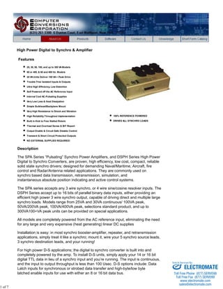
  • 1. High Power Digital to Synchro & Amplifier Features 25, 30, 50, 100, and up to 300 VA Models 60 or 400, & 60 and 400 Hz. Models 25 VA Units Deliver 100 VA + Peak Drive Trouble Free Isolated Inputs & Outputs Ultra High Efficiency, Low Distortion Self Powered off the AC Reference Input Internal Cool AC-Pulsating Supplies Very Low Loss & Heat Dissipation Simple Bulkhead/Backplane Mount Very High Resistance to Shock and Vibration High Reliability Throughout Implementation Built in Kick to Free Stalled Rotors Thermal and Overload Sense & BIT Report Output Enable & Circuit Safe Disable Control Transient & Short Circuit Protected Outputs NO EXTERNAL SUPPLIES REQUIRED! 100% REFERENCE POWERED DRIVES ALL SYNCHRO LOADS Description The SPA Series “Pulsating” Synchro Power Amplifiers, and DSPH Series High Power Digital to Synchro Converters, are proven, high efficiency, low cost, compact, reliable solid state synchro drivers; designed for demanding Naval/Maritime, Aircraft, fire control and Radar/Antenna related applications. They are commonly used on synchro based data transmission, retransmission, simulation, and instantaneous absolute position indicating and active control systems. The SPA series accepts any 3 wire synchro, or 4 wire sine/cosine resolver inputs. The DSPH Series accept up to 16 bits of parallel binary data inputs, either providing an efficient high power 3 wire synchro output, capable of driving direct and multiple large synchro loads. Models range from 25VA and 30VA continuous/ 100VA peak, 50VA/200VA peak, 100VA/400VA peak, selections standard product, and up to 300VA100+VA peak units can be provided on special applications. All models are completely powered from the AC reference input, eliminating the need for any large and very expensive (heat generating) linear DC supplies Installation is easy: in most synchro booster-amplifier, repeater, and retransmission applications, simply treat it like a synchro; mount it, wire your 5 synchro source leads, 3 synchro destination leads, and your running! For high power D-S applications; the digital to synchro converter is built into and completely powered by the amp. To install D-S units, simply apply your 14 or 16 bit digital TTL data in lieu of a synchro input and you’re running. The input is continuous, and the input to output throughput is less than 100 Usec. D-S options include: Data Latch inputs for synchronous or strobed data transfer and high-byte/low byte latched enable inputs for use with either an 8 or 16 bit data bus. 1 of 7 Sold & Serviced By: ELECTROMATE Toll Free Phone (877) SERVO98 Toll Free Fax (877) SERV099 www.electromate.com sales@electromate.com
  • 2. Dynamic Power Supply The outputs are powered by an internal, transformer isolated, purely AC dynamic power supply that efficiently transfers the AC reference input power to the outputs, in a natural AC flowing format yielding very low loss. The power supply produces unfiltered, full-wave rectified positive and negative voltages. These voltages are always in phase with the amplifier output voltages since the power is derived from the reference input. Optimum efficiency is achieved by essentially using as much AC direct power transfer as possible to drive the AC outputs because there is no DC conversion in the power transfer and the amplitude of the internal AC power rails need only be a few volts greater than the voltages driven on the outputs. Because the outputs are allowed to follow the reference input (synchro’s and converters use ratio accuracy), these supplies only need to be a small percentage higher in voltage than the amplifiers maximum output voltage to accommodate the headroom required of the circuit. The lower the voltage differential required input to output (considering the internal transformers), to drive the load; the minimum the power loss (in the form of heat), and the greater the efficiency of the amp. 2 of 7 Sold & Serviced By: ELECTROMATE Toll Free Phone (877) SERVO98 Toll Free Fax (877) SERV099 www.electromate.com sales@electromate.com
  • 3. Using this AC pulsating power technique, the output signals are tightly coupled to the reference input and the only power dissipated is the current times the small voltage difference between the pulsating power stage and the synchro signal outputs. Because both the power stage and the signal outputs are sinusoidal, and the power stages headroom is very small, the power required to drive the load is minimal. Thus the Reference Powered Synchro Amplifiers provide the highest efficiency attainable, low loss, and minimum heat dissipation. Because there is no internal high frequency PWM or charge-pump switching, there is no RF switching noise emitted from the unit or discontinuity in the outputs to compromise other user circuits, and the outputs are inherently compatible with all and any existing synchro converters. Using this type of “dynamic power transfer technique,” the efficiency is nominally better than 80% and loss (power dissipation & heat generation) for reactive loads is less than half that of conventional DC powered amplifiers. Care should be take to minimize the phase shift between the reference and signal inputs. Since the power supplies are only a few volts greater than the signal, the output could be affected by phase shift. Phase shift effect, compensation, and management techniques are detailed in CCC ap.note#G-SA1 “Driving Synchro Loads.” Packaging/Conductive Cooling These models are all self-contained in an easy to install “Bolt-On” bulkhead mount chassis. The chassis is a light weight, single piece aluminum 1/8” thick solid base plate, that provides excellent thermal transfer for conductive cooling of the unit. Mounting and Thermal Considerations: Since the unit is primarily conduction cooled, make sure that it is tightly mounted to an appropriately large, thermally conductive (unpainted) surface. Thermal grease can also be applied to the mounting surface. Kick Circuit For Torque Receiver applications, a kick circuit is provided to free stalled rotors, simply wire a jumper between the “CO” (current overload) output, and the “Kick” input. 3 of 7 Sold & Serviced By: ELECTROMATE Toll Free Phone (877) SERVO98 Toll Free Fax (877) SERV099 www.electromate.com sales@electromate.com
  • 4. More common an occurrence with large digital or switched step inputs, or after power up; a synchro torque receiver may get hung up at a false null, and just sit there and vibrate while draining large circulating currents. The amplifier will sense the overload that occurs if the rotor is persistently drawing too much current trying (unsuccessfully) to move the shaft load, and (with the kick/CO jumper installed) the amp will automatically shift the output by 120 degrees for a nominal 1/2 second duration to free the rotor from the false null. Once the rotor is put in motion, it has greater control of its output. Use this feature only if at least one Torque Receiver is being driven from the outputs. Disable Input The disable input is a TTL compatible Opto-Isolated input used to provide a circuit-safe means of disabling (turning off & on) the amplifier outputs for various applications. When disabled, the outputs appear as an open circuit to the load. The disable can be used to sequentially power up the synchro amps if several are used in a power sensitive application, or when used where the synchro signal outputs are going through switching relays for auxiliary, back-up, or test systems. The disabling the outputs prior to switching either the reference/power inputs or the stator outputs, or both, and then driving the synchro amp inputs to match the angle dictated on the destination source prior enabling the outputs. The relays can very safely switch these points without any appreciable power demand during the actual switching. This will provide a very smooth transition that will reduce surges, and inductive content, allowing the user to minimize the required size of the relays, and dramatically increase the life of any relays used for switching these (high power) terminations. A logic 1 is used to disable the power outputs, a logic 0 will will enable the outputs providing the unit is powered and is not in a thermal overload sensed condition. BIT Output The Built-in-test output is a TTL compatible Opto-Isolated output that uses a logic level 1 to indicate that the amplifier has sensed either a thermal overload condition forcing it to shut down its outputs until the internal temperature cools down, or a current overload that is straining and thereby distorting the outputs, until the load is recovered (or kicked to free a stalled rotor), or if in thermal overload (when the internal temperatures sense shuts down the outputs). Current-Load Sense The output current on 25VA units is limited to 1.0 amp peak, and approximately 1 amp/25VA on larger units, after a 4 second nominal delay; an over current indication is sensed, setting the BIT output to a logic 1 (see Built-in-test, above). When Driving Torque Receivers, the current limiting is typically experience whenever the rotor is off null (any significant difference in angle, from where it is being commanded to go), typically activating the kick circuit to rapidly set the driven synchro in motion (to free the rotor from hang-up), allowing the rotor to move towards its commanded angle (=null). Thermal Sense These synchro amplifiers are thermally protected, the amplifier outputs will shut down when the internal temperature reaches 125oC, also setting the BIT output to a logic 1. Thermal overload recovers when the internal temperature recovers. ~~~~~~~~~~~~~~~~~~~~SPECIFICATIONS:~~~~~~~~~~~~~~~~~~~~ Digital Inputs/Outputs: (All Units) *Disable...Input (DIS): Logic “0” = L=OVDC Enables Power Amplifier Output, TTL Compatible, requires 2.5ma. at logic 0 **Isolation: OptoIsolated - 1000V Peak min. Breakdown voltage to Ground. 4 of 7 Sold & Serviced By: ELECTROMATE Toll Free Phone (877) SERVO98 Toll Free Fax (877) SERV099 www.electromate.com sales@electromate.com
  • 5. Built-in-test: Output, Overload Indicator (BIT): logic level 1=H, drives 2 TTL loads, indicates amplifier sensed over load condition forcing it to shut down its outputs until conditions are satisfied (see txt). * Providing unit is not in thermal overload; internal Temperature is less than 125oC. 1. * Synchro Outputs when disabled 2. are as open circuit, high impedance state. ** On D-S units (having internal Digital to Synchro Converter); no external +5VDC is required, uses internal isolated +5VDC supply, the +5VRTN (see block dia.) is same as the digital data common only. 3. **Isolation: OptoIsolated - 1000V Peak min. Breakdown voltage to Ground. Kick Circuit: Kick & CO (Kick input & current over load); are normally connected for Torque Receiver Loads (not for Passive CT of CDX loads); If Output is hung-up due to excessive current output; Shifts output 120o for .5 sec. to unjam rotor hang-up. (see txt). Notes: Signal Inputs: (A) Synchro: 90VL-L 400Hz +10% (400 Hz) Impedence = 400K Ohms min. balanced (A) Synchro: 90V L-L 60Hz +5 % (60 & 60/400 Hz) Impedence = 100K Ohms min balanced (D) Synchro: 11.8V L-L 400Hz +10% Impedence = 26K Ohms min. balanced (B) **Resolver: 6.81V L-L @ 400Hz or 60Hz +10 % Impedence = 4K Ohms min balanced (C) ***Resolver: 6.0V L-L @ 400Hz or 60Hz +10% Impedence = 4K Ohms min balanced Notes: *1) P/N Codes See Model Selection Guide **2) Typical Resolver Input format for synchro outputs: when driven by a D-R converter operating on +15 VDC supplies. ***3)When driven by a D-R converter operating on +12 VDC supplies. Signal Input Isolation: Internally Transformer Isolated; 500VDC min. Breakdown Voltage to Gnd. DC Power Input for BIT/EN Opto-Isolators: +5V DC.+10% @ 10ma MAX. (Not required on -P units, add a P to end of P/N) Synchro Outputs: Synchro Output: 90V. Output Models: 90V L-L +1%: 25VA Models: Drives Zso = 243 Ohms (Passive CT & CDX type loads) Drives Zss = 6 Ohms (Active Torque Receiver type loads 30VA Models: Drives Zso = 202 Ohms, Zss 6 Ohms 50VA Models: Drives Zso = 122 Ohms, Zss 3 Ohms 100VA Models: Drives Zso = 61 Ohms, Zss 1.5 Ohms Synchro Output: 11.8V. Output Models: 11.8V L-L +1%: 15VA Models: Drives Zso = 6.9 Ohms 25VA Models: Drives Zso = 4.2 Ohms 5 of 7 Sold & Serviced By: ELECTROMATE Toll Free Phone (877) SERVO98 Toll Free Fax (877) SERV099 www.electromate.com sales@electromate.com
  • 6. *ACCURACY: +3 arc. minutes for passive CT & CDX loads +6 arc. minutes typical, +10 arc. minutes worse case for active aTorque Receiver (TR) type loads. *Shown for Synchro Amplifier Types, for internal 14 bit D-S add 4, 16 bit add 2, arc. minutes. *Reference Power Input:(Amplifiers) **90V. Signals, 25VA Models: (400 Hz.) 115V. RMS +10%, 360-440 Hz. @ 60 ma.** (60 Hz.) 115V. RMS +10%, 57-63 Hz. @ 100 ma.** (60 & 400) 115V. RMS +10%, 57-440 Hz. @ 100 ma.** 90V. Signals, 60 Hz. 100VA Model: (Typical/Measured) 725 ma. no load, +1.122ma. of input/ma. of output. **11.8V. Signals, 25VA Models: (400 Hz.) 26V. RMS +10%, 360-440 Hz. @ n1 ma. (No load) plus n2 ma. per ma. of output load. TEMPERATURE: (BEST IN CLASS!) Operating Temperature Range: -40oC to +85oC Storage Temperature Range: -55oC to +125oC Heat Dissipation:1.5 watts/VA to load. (25 & 30VA.) Notes: * Reference 1. input must be in phase with signal inputs and signal outputs. 2. ** (No load) plus 1 ma. per ma. of output load. 3. 25VA units; 1 A. typ. draw w/output short circuit. MODEL SELECTION GUIDE FOR SYNCHRO POWER BOOSTERS (AMPLIFIERS) MODEL Option Internal +5VDC used for EN/BIT Output POWER VA Frequency INPUTS-POWER & SIGNALS OUTPUTS WEIGHT SIZE Reference & POWER INPUTS SIGNAL INPUTS V.L-L Balanced SIGNAL INPUT FORMAT SYN/RES Synchro Format in V.L-L Balanced WEIGHT Package Drawing Code SPA2560-A -P 25VA 60Hz. 115VAC 90V.L-L Synchro 90V.L-L 4.75 lbs. B SPA2560-B -P 6.81V.L-L Resolver 7.4”Lx2.6”H SPA2560-C -P 6.0V.L-L Sin/Cos SPA2540-D-P included 25VA 400Hz. 26/115VAC 11.8 Synchro 11.8V.L-L 3.25 lbs. A 5.09”W x 7.4”Lx1.84”H SPA2540-A -P 115VAC 90 Synchro SPA2540-B -P 6.81V.L-L Resolver 90V.L-L 3.25 lbs. SPA2540-C -P 6.0V.L-L Sin/Cos SPA25B-A -P 25VA BOTH 60 or 400Hz. 115VAC 90 Synchro 90V.L-L 4.75 lbs. B SPA25B-B -P 6.81V.L-L Resolver 7.4”Lx2.6”H SPA25B-C -P 6.0V.L-L Sin/Cos SPA3060-A -P 30VA 60Hz. 115VAC 90 Synchro 90V.L-L 4.75 lbs. B SPA3060-B -P 6.81V.L-L Resolver 7.4”Lx2.6”H SPA3060-C -P 6.0V.L-L Sin/Cos SPA3040-A -P 30VA 400Hz. 115VAC 90 Synchro 90V.L-L 4.75 lbs. A SPA3040-B -P 6.81V.L-L Resolver 7.4”Lx1.84”H Sin/Cos Sold & Serviced By: SPA3040-C -P 6.0V.L-L SPA5060-A -P 50VA 60Hz. 115VAC 90 Synchro 90V.L-L 7.0 lbs. C 6 of 7 ELECTROMATE Toll Free Phone (877) SERVO98 Toll Free Fax (877) SERV099 www.electromate.com sales@electromate.com
  • 7. 5.1”W x 9.31”L x 2.75”H SPA5060-B -P 6.81V.L-L Resolver SPA5060-C -P 6.0V.L-L Sin/Cos SPA1040-A -P 100VA 400Hz. 115VAC 90 Synchro 90V.L-L 5.75 lbs. C 5.1”W x 9.31”L x 2.75”H SPA1040-B -P 6.81V.L-L Resolver SPA1040-C -P 6.0V.L-L Sin/Cos SPA1060-A -P 100VA 60Hz. 115VAC 90 Synchro 90V.L-L 8.0 lbs. D 5.1”W x 9.31”L x 3.31”H SPA1060-B -P 6.81V.L-L Resolver SPA1060-C -P 6.0V.L-L Sin/Cos SPA10B-A -P 100VA BOTH 60 OR 400Hz. 115VAC 90 Synchro 90V.L-L 8.0 lbs. D 5.1”W x 9.31”L x 3.31”H SPA10B-B -P 6.81V.L-L Resolver SPA10B-C -P 6.0V.L-L Sin/Cos 400Hz. 115VAC 6.81V.L-L Resolver SPB2054-52-B -P 200VA 50,60 OR Sin/Cos 52V.L-L 32.0 lbs. C7972 8.8”W x 15.0”L x 3.7”H Notes: 1. Add -P to end of model # for units with internal +5VDC power supply, (no external supplies required). 2. Use 6.81V. signal inputs when driven by Bus Cards PCI, VME, D-S cards using +15VDC supplies. 3. Use 6.0V. signal inputs when driven with Bus Cards PCI, VME, D-S cards using +12VDC supplies. 4. Use E in part number in lieu of -A, -B, -C, when driven by our cPCI Cards. CCC app.note #G-SA1 “Driving Synchro Loads” Request Full Data Sheet Copyright © 2012 7 of 7 Sold & Serviced By: ELECTROMATE Toll Free Phone (877) SERVO98 Toll Free Fax (877) SERV099 www.electromate.com sales@electromate.com