Recomendados

Recomendados
Mais conteúdo relacionado
Destaque
Destaque (20)
SEPnet poster
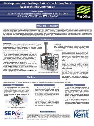
- 1. Most Rain is created when tiny water droplets in clouds become ice crystals and bind together. This makes them heavy enough to fall from the sky. To become ice, the water droplets need a solid particle to crystallize around or initiate freezing; often a piece of dust. This process is called ice nucleation. Without the presence of these microscopic dust particles or Ice Nuclei (IN), as they are known, the super-cooled (i.e. below 0˚C) water must reach ~-40˚C before it will freeze. This seems counterintuitive as we all know water freezes below 0˚C. This is because the water we encounter in ‘everyday situations’ is full of crystalline impurities which instigate the freezing, whereas, clouds at high altitude contain super-cooled water vapor and droplets without impurities which will be affected by the presence of IN. It is, therefore, important to study and understand the transfer of IN such as dust, sea salt and smoke into clouds and the characteristics of the IN such as their activation properties. Development and Testing of Airborne Atmospheric Research Instrumentation Alec Hammond Research and Development Summer Placement at The Met Office University of Kent (4th year MPhys Student) Introduction What are Ice Nuclei? Acknowledgements My Role What is the INC? During my summer placement, I worked closely within a team, in particular, focusing on the Ice Nucleus Counter (INC) which is being developed to further understand the nature the enigmatic processes of Ice Nucleation. It has the capacity to take airborne samples and re-create Ice Nucleation conditions within the column (see Fig. 1). Here's how it works: As a key part of the INC, my main task was to design and help build the Evaporator section of the INC . Each stage is broken down below. Main ‘science’ happens within the column chamber. This consists of two co-centric cylinders of different diameter, one inside the other, leaving a thin annular gap or ‘chamber’. The chamber is super-cooled before being pumped and then drained of water very quickly to produce a thin layer of ice on the inside walls. The refrigerator system controls the temperatures of the inside and outside walls and therefore can produce a water vapour pressure gradient between the two iced walls. The airflow system creates a ‘sheath’ of dry air into which the sample air enters and descends the length of the column. An evaporation section at the bottom of the chamber allows water droplets that have formed in the chamber to be removed so as not to affect the reliability of results. Filters at the inlet only allow in a certain particle size range and concentration that can then be monitored. Identifying IN: Step1: Sample air enters the chamber through an inlet on the outside of the research aircraft. The inlet only allows in particles of a certain size range and of known sample concentration. The particles are candidates for IN. Step 2: Conditions are set in the chamber by adjusting the temperature of the two surface walls. The water vapour pressure gradient between the two walls means that naturally the water vapour, sourced from the iced walls, will flow from the higher pressure region to the lower pressure region (one wall to the other). Step 3: As the sample air is injected and travels through the chamber, particles of the correct crystalline structure will form ice crystals, increasing significantly in size, while the others will pass straight through unchanged. Step 4: Large particle filters separate successful IN from other particles at the chamber exit and so by calculating the difference in the number of particles that entered the chamber and the number that were left unchanged upon exiting the chamber a representation of IN concentrations within samples may be gained. Fig.1: Column and airflow components of the INC Foremost, I would like to express my sincere gratitude to each and every one of the OBR team at the Met Office, especially Joss Kent and Clare Lee, for their friendship and guidance throughout my placement, as well as, Richard Cotton for making my role possible. I must also extend my thanks to SEPnet for providing the funding and opportunity, without which my placement would not have been possible. Figure 1 is credited to Richard Cotton. This involved learning and using Computer-Aided- Design (CAD) software and creating a true scale model of the evaporator system from a circuit diagram adhering to spatial and weight restrictions. Problem Solving skills were essential to ensuring that the design was as simple and efficient as possible. Design Build Test After many design stages and the final construction had been decided, it was possible to have each piece made up and sent off to be anodized. Some of the less specialised components were made up in the lab as part of my role with help and training from Andy Wilson which was a great hands-on experience. Before being built, it was possible to create prototypes of some of the brackets and supports using the departments 3D printer which created parts from a durable polymer. This could be done directly from the CAD software. Due to the large scale and on-going work on the INC I was unable to take part in the ‘test‘ stage of my particular piece of work. However, I was involved in COPE – the (CO)nvective (P)recipitation (E)xperiment, where I shadowed the OBR team and learnt how equipment is tested in the field and the data is analysed and discussed post flight. The INC aims to be functioning properly by 2015 where it’s first objective will be to measure the effect of Saharan dust storms on the transfer of IN to clouds and the effects of IN on cumulus cloud evolution. Fig. 2: Design Stage of Evaporator Section